0a. Electronic stuff is made of magic (smoke):
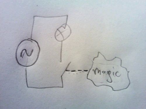
0b. Ok, let's draw it a bit more professional:
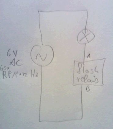
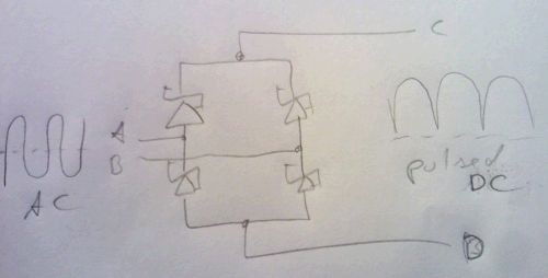
1. a bridge rectifier ensures the right polarity.
2. a resistor charges a capacitor, a voltage divider triggers a triac after some time:
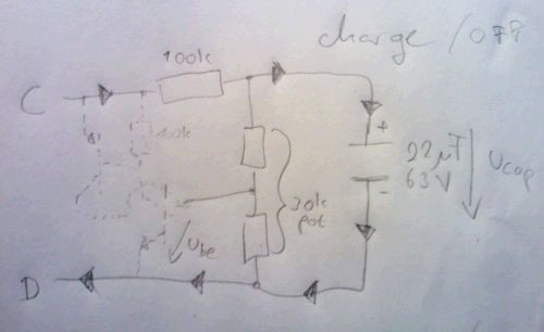
3. the triac shortens the two terminals. this turns on the turn light(s) and slowly discharges the capacitor:
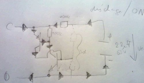
4. The cycle starts again beecause the "triac" does not fire for the supply pulses as the base voltage/current of the NPN transistor is too low.
Overall circuit (first sketch, no part values):
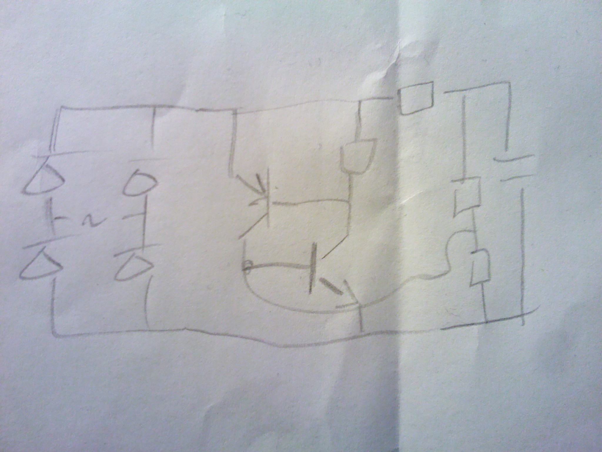
The design is related to this one. No triac is involved. Instead, two high-current bipolar transistors form a thyristor. The additional collector resistor on the base of the PNP /collector of NPN transistor pulls the base of the PNP transistor high, reducing the overall loop gain. If the circuit does not "flip", this is one location to adjust.
A quick prototype looks like this:
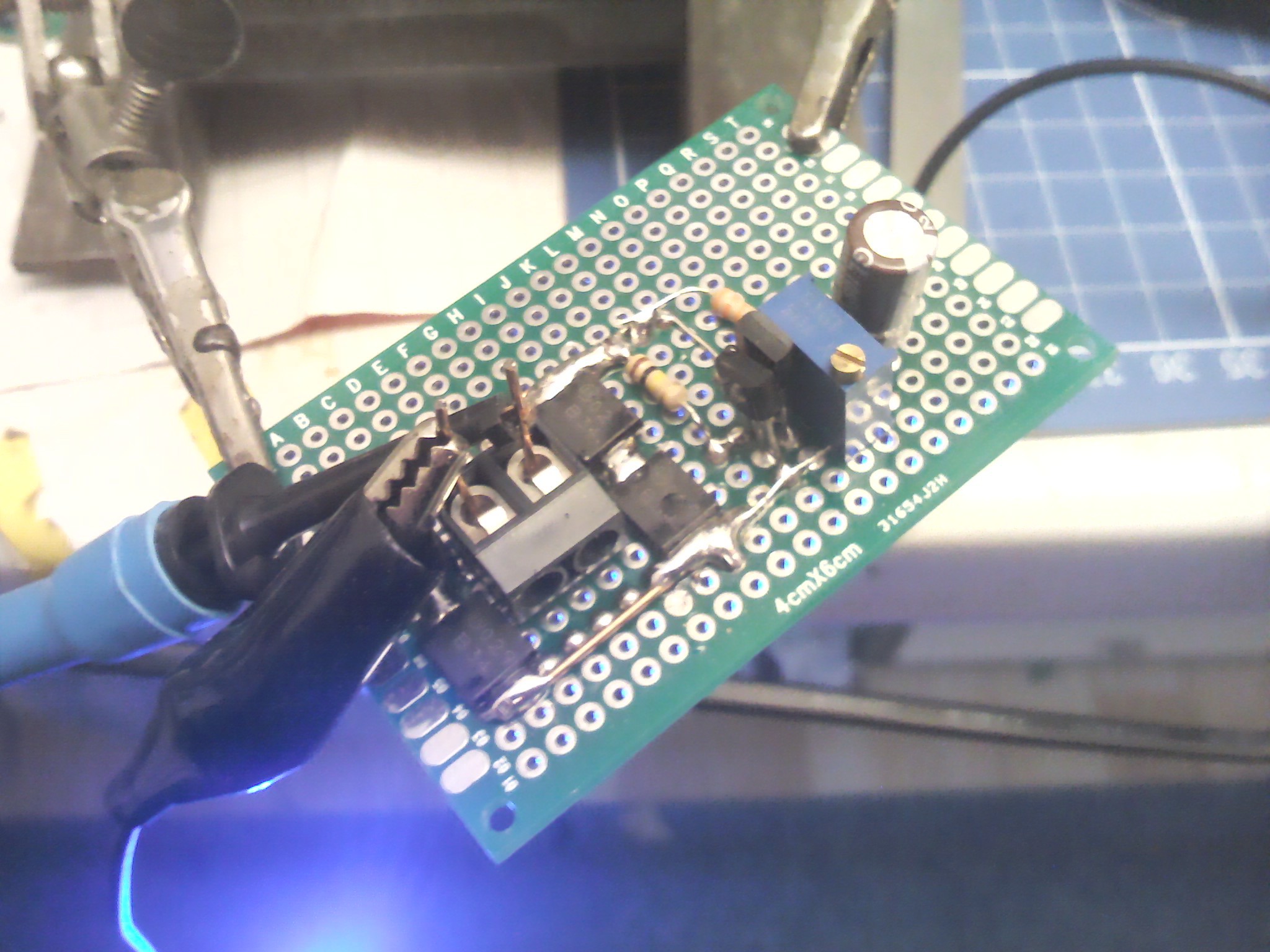
...and (I was surprised myself) works after adjusting the pot:
The flashing frequency/period does depend on the load on a tiiiiny amount: During the charge phase of the electrolytic cap the charging resistor (about 100k) is much larger than the load (a few ohms) which means the charging duration will be more or less the same. During the discharge phase, the "triac" sets a certain voltage which is more or less independent of the load, which results in a discharge speed which is more or less independent of the load. This is proven by experiment: A tiny light bulb results in the same frequency as 4Ohm load (=6V / 4Ohm = 1.5 Amps ; 9 Watt). The load resistors get reasonably warm while for the circuit itself it is hard to notice heat. Discharge time is not influenced by supply voltage, but charging time is. With rising supply voltage, on time stays approx. constant but off time reduces.
 rawe
rawe