Overview:
The display shows the following:
-Battery Voltage
-Input Voltage (wind, solar, etc) (averaged over the last ten readings)
-Amperage (averaged over the last ten readings)
-Wattage (averaged)
-Transistor Temperature and Duty Cycle (these two values alternate between each other)
-Amp-Hour counter
As far as features go:
-Automatic backlight control; if no input voltage for 60 seconds, backlight turns off
-Automatic reset of Amp-hour counter if an hour elapses with no input voltage
There might be enough overhead left to stream serial data to a PC, but I would recommend using a 16 mHz MCU. This code is written specifically for a 12 volt system with the charger in charge control mode. There are options for 24 and 48 volt settings which do change the scale of some of the voltage readings as well as other unknowns.
Schematic:
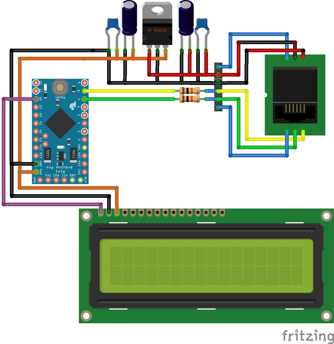
The schematics are fairly straightforward. The important bit is the wiring of the RJ25 plug:
- LED A
- Comm 1
- Comm 2
- Ground
- V+ (8 volts)
- Led B
Pardon the LCD, Fritzing doesn't have a serial LCD I could pick from. The purple lead is merely a serial Tx from the Arduino. The two LED leads are currently not being used, but otherwise are used to relocate the status LED that is normally found on the charger.
Source Code:
Ultimately the code is not as clean as I care for, but with the challenge of not using any interrupts it was necessary to break up functions and control when they could execute. This is done by using the time between bytes (which is longer than the time between bits) to perform calculations and stream data to the LCD. I tried to be healthy with the use of comments so hopefully it makes a little sense!
This is all written under the Arduino 1.0.6 IDE.
/*Digital Volt Meter for the Xantrex C-series charge/load controllers. Configured to read the obscure communication
protocol they use and display the information on a 2x16 Parallax LCD. Displays battery voltage, average amperage,
watts (calculated from average amps), input voltage, transistor temperature, duty cycle and total amp-hours. LCD
backlight is programmed to turn off after a period of no charging to conserve power and serve as a night mode, amp-hour
counter is also programmed to reset at night so amp-hour counter will perform as a daily counter, not total.*/

#include SoftwareSerial lcdSerial(11,12); //rx,tx configure softwareserial for LCD

//pin declarations
#define comm1pin 7
#define comm2pin 8
#define LED 13
#define LCDrx 11
#define LCDtx 12

//configurations declarations
#define noPowerTimeLimit 60000 //time in milliseconds in which display backlight turns off if not charging
#define noPowerAHTimeLimit 3600000 //time in milliseconds in which Amp-Hour counter resets (1 hour = 3600000)
#define yesPowerTimeLimit 5000 //time in milliseconds in which display backlight turns on if charging begins
#define avgAmpArraySize 10 //number of readings to keep in avgAmp (rolling average)
#define avgPvArraySize 10
#define commTimeout 5 //time in milliseconds both comm can be low before it's considered a timeout (time between bytes)

boolean tempOrDuty = true; //boolean for selecting whether temp or duty cycle is currently displayed
boolean commCheck = true; //boolean for latching communicatons logic, when true MCU will check for comm high
boolean resetTimeLimit = true;
boolean backLightOff = false; //status of whether backlight is enabled or not
boolean lastStateAmp = true;
byte syncCount = 0; //status as to whether a sync signal has been received, used to prevent writing to LCD until good data is present
byte temp = 0; //temp storage for byte in progress
byte comm1=0; //register for comm1 status
byte comm2=0; //register for comm2 status
byte count = 0; //count of number of bits stored in temp
byte byteCount = 0; //count of number of bytes collected since last sync
byte transTemp = 0; //transistor temp of charger
byte battTemp = 0; //battery temp
byte toggleCount = 0; //counter for how long to display temp or duty cycle; incremented by number of sync cycles
byte dutyCycle = 0;...
Read more »
 Eric Herbers


 Lex Kravitz
 Roman
Roman

I'm looking to build multiple units that can interface with the C35/40/60 charge controllers, TrueCharge Chargers, and Freedom Inverter/Chargers and send the data to a Single Board Computer like a Raspberry PI over an RS-485 serial link.