-
Not done!
05/04/2015 at 03:46 • 0 commentsAfter posting my findings on a post on allaboutcircuits it was pointed out that byte 1 really should be battery voltage. After a little investigation (and wiring in a battery temp sensor) I found that what I had been using (byte 13) was actually a comparator value for the charging logic that factored in battery temperature (causing the battery to charge to a lower voltage if it is hot).
Ultimately I found that my logic for checking the two comm lines had a fault: It assumed both went high at exactly the same time. The fallacy in that logic is that any MCU takes a number of clock cycles between actions so it can't realistically bring both high at exactly the same time. Granted, the Arduino isn't checking them at exactly the same time either, but it was painfully obvious that I was not catching them both reliably.
By writing in some logic that causes the Arduino to delay a millisecond and then check the other comm a second time ensures that it can reliably capture the sync events, leading me to reliable data for byte 0. Early on I had dismissed it as I was largely getting garbage data; that was a mistake.
I've updated the source code to correct this and will work on a schematic next.
-
And done!
04/29/2015 at 04:15 • 0 commentsI think I'll call it good at this point. Aside from intermittently getting out of sync the display is working to satisfaction and formatted in a fashion I'm happy with. Look to the project details for what the display does as well as source code.
-
Nothing Special
04/24/2015 at 16:55 • 0 commentsShort update: Thanks to home projects I hadn't met my goal of completing this one, but progress has been made!
I've decrypted enough information to at least get the core necessities; voltage, amperage and temperature. At this point I'm working on formatting information for the LCD, primarily trying to come up with icons so I can manage the limited space better.
While an 8 mHz microcontroller is doing the job, 16 mHz would be so much better! Since I'm using softwareserial to talk to the LCD (so hardware serial can be left open for debugging) I was running into problems with not being able to keep the overhead low enough that it still caught every bit. Ultimately I had to increase complexity in the code a bit by making the MCU update only portions of calculations and the LCD at a time rather than doing everything at once. This seems to have resolved the problem.
Had I not been using parts I had laying around, a 16 mHz MCU would have been my first choice.
Next up will be focusing on features such as turning off the LCD backlight when there is no solar power to help conserve energy as well as decided how to handle the amp-hour counter; I've yet to decide if I should keep a life-time counter or have it reset at night and only keep track of daily counts.
-
Excelling in Excel
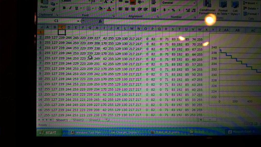
04/11/2015 at 05:05 • 0 commentsNow that I was capturing reliable bytes of data, it was time to start decrypting what they meant. There are still a number of unknowns, but quite a few were identified simply by dumping the results in Excel and observing how the values changed. I also ended up hooking a car charger to the PV input on the charge controller and monitored an actual charge cycle while measuring voltages and changing the current from the car charger. This is tedious work with a fair amount of guessing, but it still pays off with much of the core necessary information identified.
Ultimately the trick is to get the Arduino to stream the data out to the serial terminal, using commas to separate data and the print line function to start a new line of data. This can be copied and then pasted into Excel using the text import function quickly and easily. With everything sorted into columns and rows, you can use the scatter graph feature to plot out the data and get an idea of what is being viewed. By logging data while doing controlled actions with the charger you can break down a lot of the mysteries.
![]()
Byte: Description (all conversion formulas are for the 12 volt operating mode)
1: The starting byte of the string, signified by both comm lines going high on the first bit. Displays battery voltage: High resolution. Value dependent on voltage mode (12, 24 or 48). Slope of 0.0755, offset of +.464
2: Current; divide by 2 to get real value.
3: Always reads a value of 126, undetermined purpose.
4: Appears to be related to wattage, but is inversed and not scaled linearly. Even applying a power doesn't yield accurate results. The results also don't match up perfectly to calculated wattage, but follows the trend.
5: PV Voltage: Slope of 0.350, offset of +.032
6: Battery Voltage: Low Resolution Scale: Conversion formula not determined yet
7: Battery Temperature: Conversion formula not determined yet
8: Almost always displays 174.
9: Status of the reset button/load or charge control selection
10: Bulk Charge Voltage Level: Slope of 0.0755, offset of +.464
11: Float Charge Voltage Level: Slope of 0.0755, offset of +.464
12: Transistor Temperature: Conversion formula not determined yet
13: Temperature Compensated Battery Voltage Comparator, increases over actual battery voltage as battery temperature rises. This causes the battery to stop charging at a low voltage if temperature is high. Slope of 0.0755, offset of +.464
14: Counter: Starts at 0, ends around 230, rolls over every minute
15: Undetermined, might be a status register, but rarely strays from 0
16: Undetermined, might be a status register, but rarely strays from 0
17: Duty Cycle: 128 = 100%, 0 =0%
18: Minutes on Float Charge, but only counts up to 23
19: Minutes on Bulk Charge, but only counts up to 11
20: Status Register: Yet to investigate
21: Status Register: bit 8: Transistor Over-temp, 7: unknown, 6: Bulk Charge, 5-1: Unknown
22: Status Register: Yet to investigate
23: Can been seen as a reasonably repetitive pattern, but undetermined what it is. Counts up from 0 to around 45, but usually rolls over after only a few iterations -
Bits and Bytes
04/08/2015 at 04:16 • 0 commentsHardware wise this project is very simple, nothing more than a serial LCD being driven by an Arduino Pro Mini. As all I'm doing is collecting data from a serial stream and formatting it onto a LCD, this could be done with much much less.
At first blush the data appeared to be your typical RS-232 or RS-485. However, upon closer inspection it was obvious that a couple things were missing. Primarily a start or stop bit and no obvious formatting; just raw bytes. A plea was tossed out to twitter and caught a surprising amount of wind thanks to the Hackaday staff, but the protocol has still not been identified. By all intents and purposes it appears to be proprietary.
The good news is that it's at a very slow rate of around 200-300 bits per second, meaning a lowly 8 mhz micro-controller can easily collect the data the simple way (using the digitalRead function and if statements). After beating my head against a wall to find a protocol, I finally said to hell with it and decided to just do it the hard way. Here's the important bits found after a few nights of testing and observation:
-23 bytes of data
-No start or stop bits; only 8 bit of data separated by a small delay
-Two communication lines; complimentary data. 0 bits are signaled by pulling one line high and 1 bits by pulling the other line high
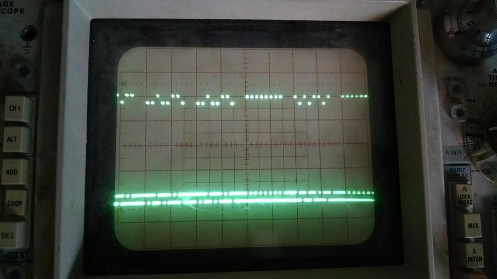
-Both lines are pulled high at the same time to denote the start of a block of bytes; most of the timeUltimately here is what the data looks like:
![]()
This being at a division of only 20 ms. The two comm lines are offset from one another to better identify the 1's and 0's.
The code to read this is pretty simple:
-Add a 1 or 0 to the byte in progress based on whether one or the other comm line is high.
-If too much delay occurs between bits, clear out the register and begin anew. This is how the bytes are initially synced and kept in sync.
-If both comm lines are high, go back to the start of the array of 23 bytes and begin repopulating it again. This is how we sync to the data so the correct bytes are associated with the correct variables.
-Since the above only occurs about 98% of the time, also keep track of how many bytes have been stored and go back to the start of the array if it grows over 23.From there the array will get processed to produce varies figures such as voltage, duty cycle, amperage, temperature, etc. For now the raw data is just dump to a serial terminal while I try to decipher in Excel what everything is. So far I've got a loose understanding of about half the bytes (and at least those being the core necessary), but there is certainly more that are an unknown.
Xantrex C35/C40/C60 Display
Replicating Xantrex's remote display with an Arduino, plus collecting more data!
 Eric Herbers
