Strain Indicator V2.0
Measuring strain using strain gauges.
Measuring strain using strain gauges.
To make the experience fit your profile, pick a username and tell us what interests you.
We found and based on your interests.
I tested the strain indicator unit with a rosette, next step would be calibrating the readings with a commercial strain indicator at college.
The readings shown on display are just the raw voltage from the Wheatstone bridges in milli-Volts, Later I'll add the rosette as well as the linear gauges equations to calculate strain using these readings, GF (gauge factor or sensitivity) which is dependant on gauge material/type and finally the orientation and bridge configuration (Full-Bridge / Quarter-Bridge).
In my case all the channels are quarter bridges with 120 Ohm SMD resistors.
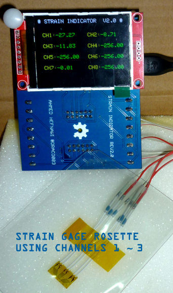
Awaiting feedback =)
Hurrah!!!
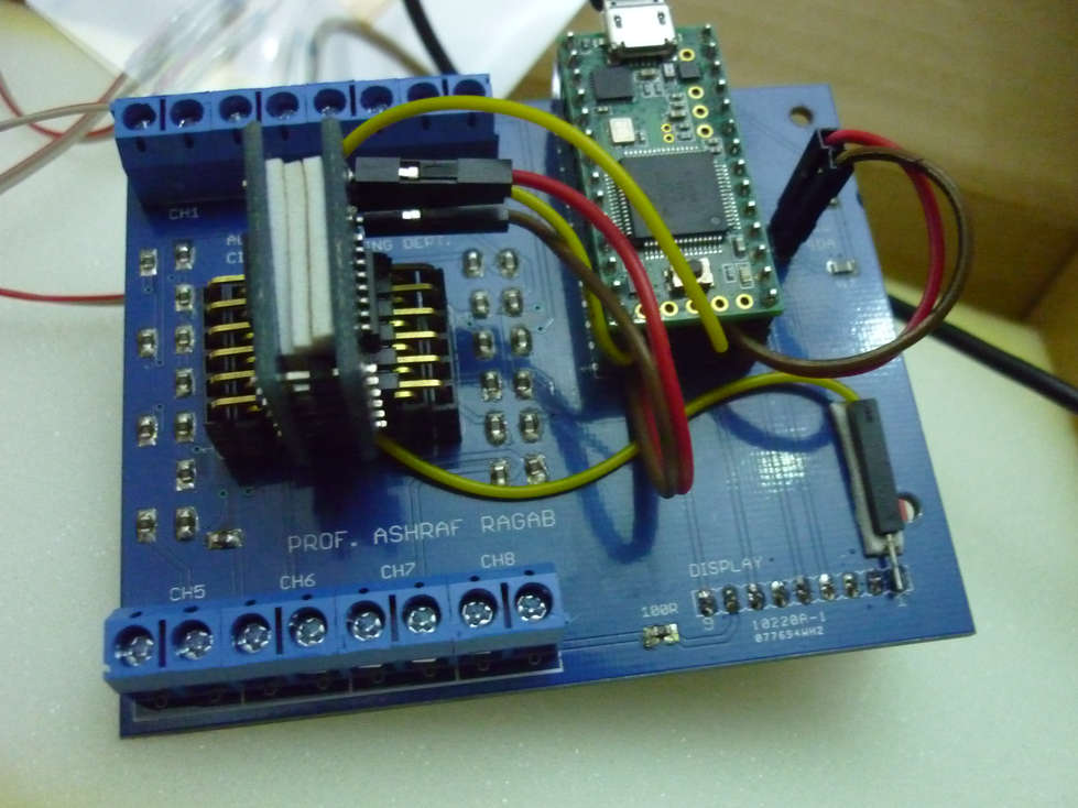
I just finished soldering all of the components to the PCB and I found out I missed a track from Teensy's VIN to the VCC of the display and all I got was the backlight LED, after a little troubleshooting with the multimeter continuity mode and reviewing my designs I added a wire (the yellow one in the photos below) going from VCC to VIN and it worked!
Btw this is my 1st try with a hot air soldering station and it went great, I used it to solder the 120 Ohm SMD resistors on the board. The rest of the components were soldered using a normal iron.
Here are some photos along the way, enjoy!
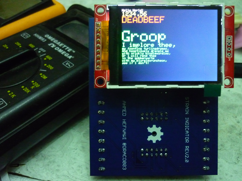
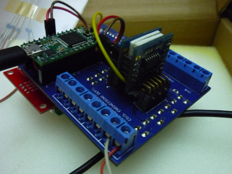
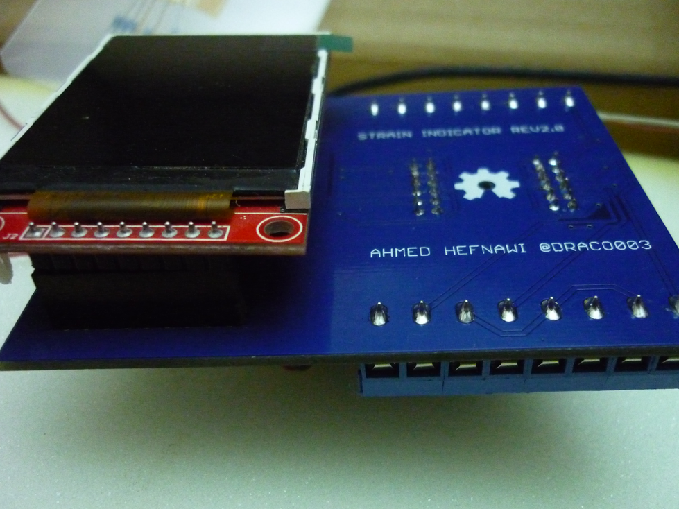
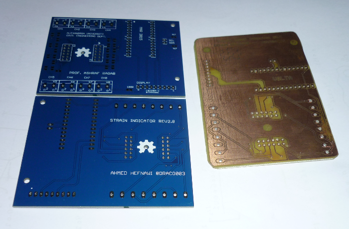
Just received my PCBs from SeeedStudio Fusion PCB service, the finish and the silkscreen are great. This is my first order with them.
Here is a photo of the PCBs and next to it is the home made version (using photoresist method).
Create an account to leave a comment. Already have an account? Log In.
Hello Romildo,
Thanks a lot!
I'm just busy with my final exams this month, so by end of Jan I'll upload the schematics for version 2.0 of the strain indicator.
Your ADC is okay for some hobbyist applications. I get all sorts of questions about strain gage sensing monthly. The short is you made a good choice on the Sigma-Delta but you overlooked some very important aspects. It doesn't have external reference ability (non-ratiometric part) and it has low gain. You should look at replacing this chip with something that is ratiometric and has gain of about 64 with 16 ENOB for most applications. As a demoing application where you don't care about drift or the like it's okay. Also, bridge completion resistors should be < 0.1% error with sub 10ppm. Otherwise a light breeze or someone's hand near the resistors will cause it to change. Good Luck
Hi @kwakeham
Thanks a lot for the advice! I come from a civil engineering background so I really appreciate it! Do you have any suggestions for a ratiometric (external ref) ADC chip?
I came across this 24-bit ADC chip: ADS1248 with ENOB: 15.1 - 19.6 @ PGA=128 it also supports internal/external reference.
Datasheet: http://pdf.datasheetarchive.com/indexerfiles/Datasheet-080/DASF0014639.pdf
I definitely want to take this to the next level.
Regarding the completion resistors what do you think of this SMD one: http://www2.mouser.com/ProductDetail/Susumu/RG1608V-121-P-T1/?qs=sGAEpiMZZMvdGkrng054t4H2ALkFV8suNcJ5SvGIJhM%3d
Sorry for my late reply, I was on the go.
Looking forward to variants using a MUCH cheaper strain gauge or combination thereof:
Display: $6.00
Teensy 3.1: $20.00
MCP3424 x 2 = $10.00
3.7V 4000mAh lipo (tablet cell) - $12.00
KFH-3-120-D17-11L1M2S strain gauge - $290.00
Certainly not cheap, but keep in mind that they come in packs of 10..
"Certainly not cheap, but keep in mind that they come in packs of 10.."
Oops, didn't see that info at the top of the table containing the part. Still, since they apparently can't be bought in unit quantities...
120 ohm, $7.50 for 5:
I think these ones will be really good for testing but I'm not sure of their quality, if any one had a go with them let us know. Thanks.
I started experimenting with the 1-Axis General Purpose priced at $67 for a pack of 10: http://www.omega.com/pptst/SGD_LINEAR1-AXIS.html
I suggest you start off with the linear general purpose strain gauges if it's your first experience with strain gauges. Also keep in mind that pre-wired ones are more expensive but they will save you the trouble trying to solder them (especially the very small ones! I learned this the hard way ^^)
Actually if you are interested I might upload version 1.0 of this indicator, it had an OLED display + ATMega328P + 9V battery + 16-bit ADC. Version 2.0 is supposed to be an upgrade with a menu feature and much more functions (such as graph of the output and force calculations) and I also wanted to experiment with Teensy 3.1 =)
Thanks for posting this! I've got a box of similar strain gauges collecting dust on a shelf--maybe I can put 'em to use now!
Thanks Zach, stay tuned for the project logs. I'm currently waiting for my PCBs to come from China (PCB Fusion - SeeedStudio).
Become a member to follow this project and never miss any updates
 Solderking
 dudeskidaddy
 Petros Kokotis
 Lithium ION
Hi Ahmed,
Congratulations. Very nice your project.
I'm try to do the same, but with a lot of simplifications.
I want to use a Raspberry pi and assemble a circuit for reading the strain gauges.
My question is about the circuit. Can you show to me the circuit and the values of the itens (resistors, diodes, etc).
Thanks.