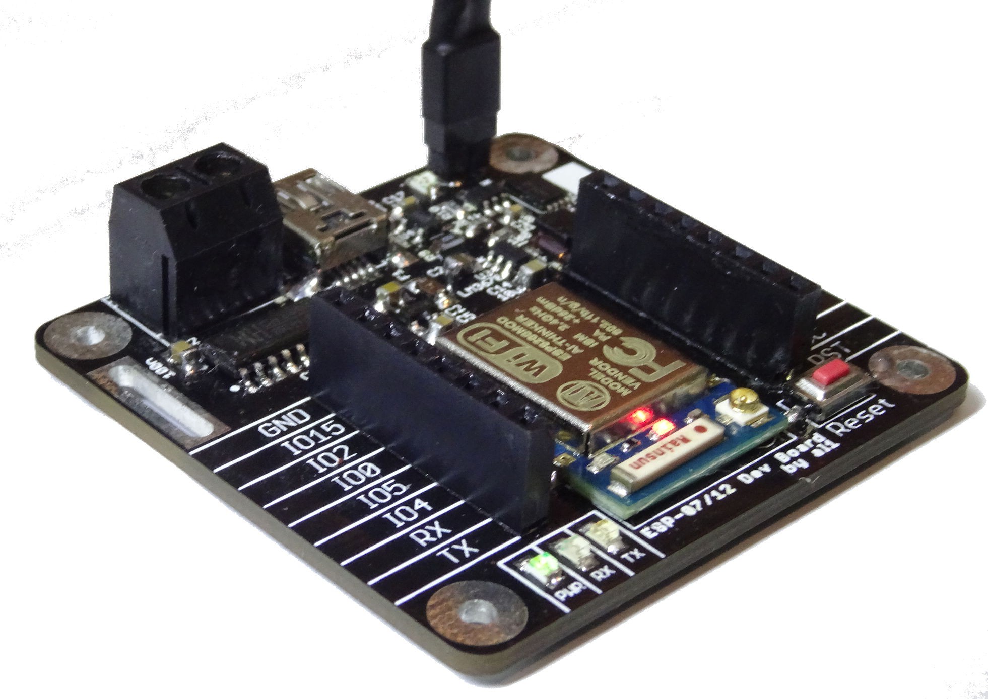
Just a quick Update: I soldered the lipo and switching regulator circuit (upper corner in picture) today. It works fine. Only minus is that i forget to make some load sharing circuit. So if charging the battery the esp itself also runs from the charge current.

 Alex
Alex
Discussions
Become a Hackaday.io Member
Create an account to leave a comment. Already have an account? Log In.
The LM3671 is quite interesting! I googled around a bit to find something that is capable to convert LiPo voltages to 3.3V and only found a polulu module so far, the S7V8F3 https://www.pololu.com/product/2122
Are you sure? yes | no
I was wondering at first, how you'd manage to run an ESP off of 4.2V safely...
Are you sure? yes | no
Yes the Version in the picture uses the LM3671 as step down for the battery voltage to 3.3V. But this is only one of two options. Instead also an AMS1117-3.3 (on the bottom of the PCB) can be used. but this is not very useful when powering from a battery because of the low efficiency.
The module from pololu should be be also suitable in a similar case. A good way to find suitable voltage regulator ICs quickly is this small webtool from TI (http://www.ti.com/lsds/ti/analog/webench/overview.page). They do only list TI parts!
Are you sure? yes | no
The AMS1117-3.3 is only a drop-down and has a voltage dropout 1V - so LiPo is out of question there... you could use 2 of them or a 9V block. But I'm looking for a 3V - 4.2V to 3.3V thing ;)
Are you sure? yes | no