Alex
Alex-
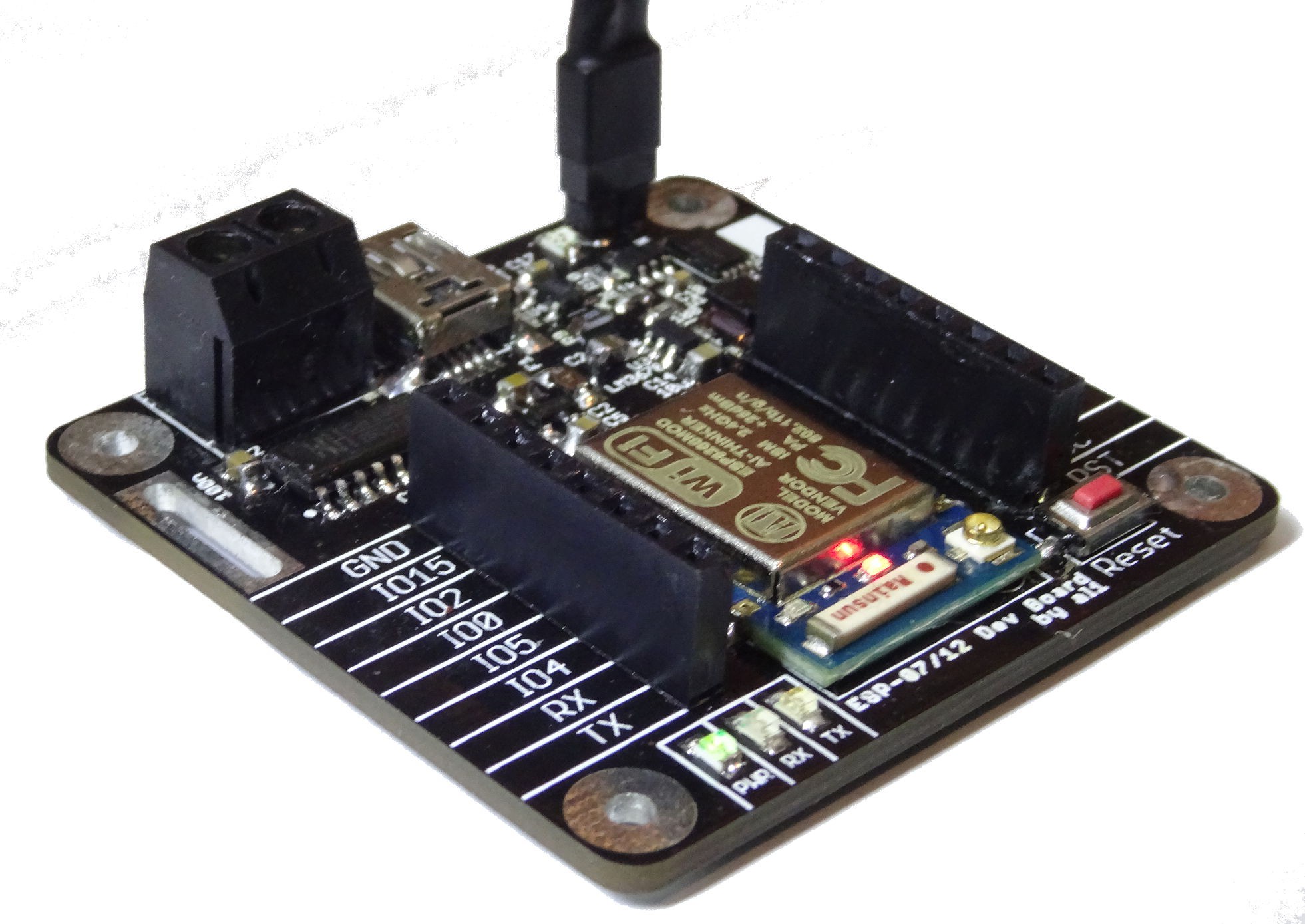
Lipo circuit is working
05/30/2015 at 18:10 • 4 commentsJust a quick Update: I soldered the lipo and switching regulator circuit (upper corner in picture) today. It works fine. Only minus is that i forget to make some load sharing circuit. So if charging the battery the esp itself also runs from the charge current.
![]()
-
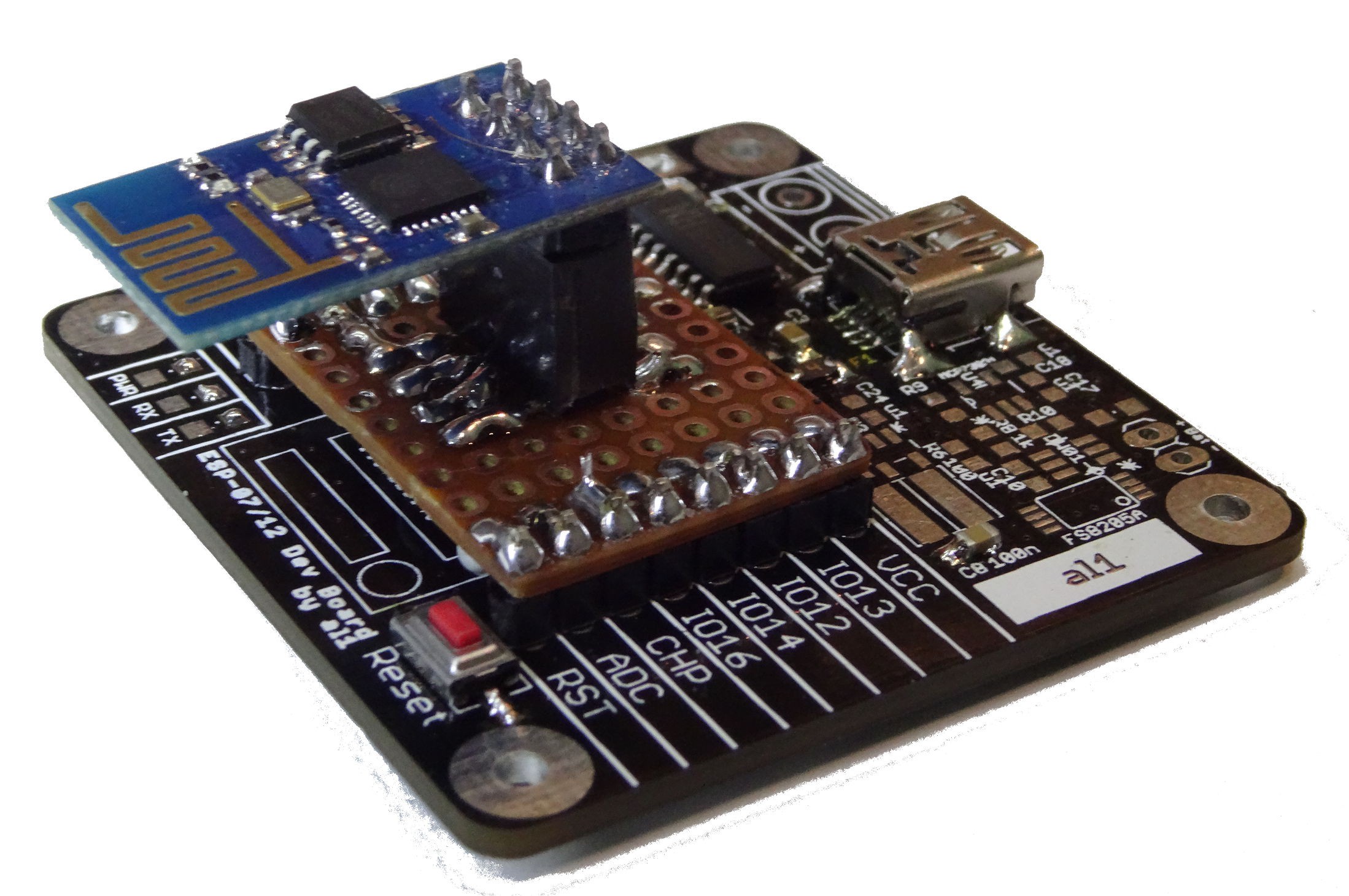
This board can be also used with ESP-01!
05/29/2015 at 16:38 • 0 commentsToday I made this:
![]()
An ESP-01 module mounted via an small adapter made of prototype board. On next revision, I think, I will include a footprint for a socket to mount ESP-01-Module directly.
-
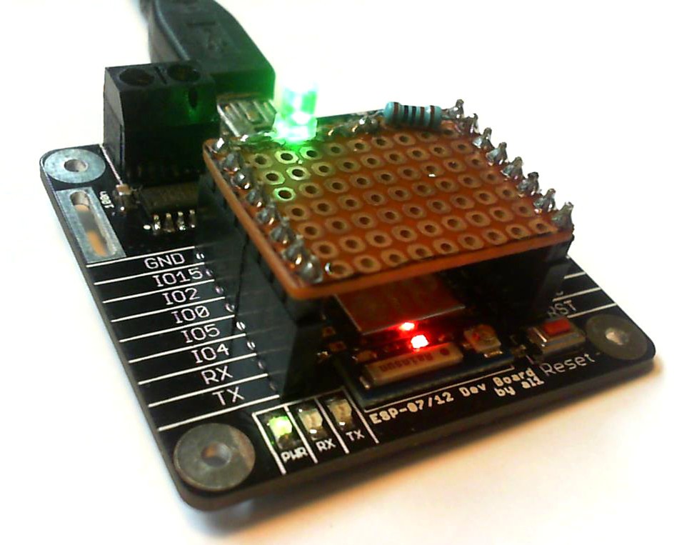
Some LED testing
05/17/2015 at 17:08 • 2 commentsToday I tested the first board. I just used the examples from the ESP Arduino IDE. Therefore I made a small Shied to connect one LED. This Shield is made out of a cheap prototype board.
![]()
-
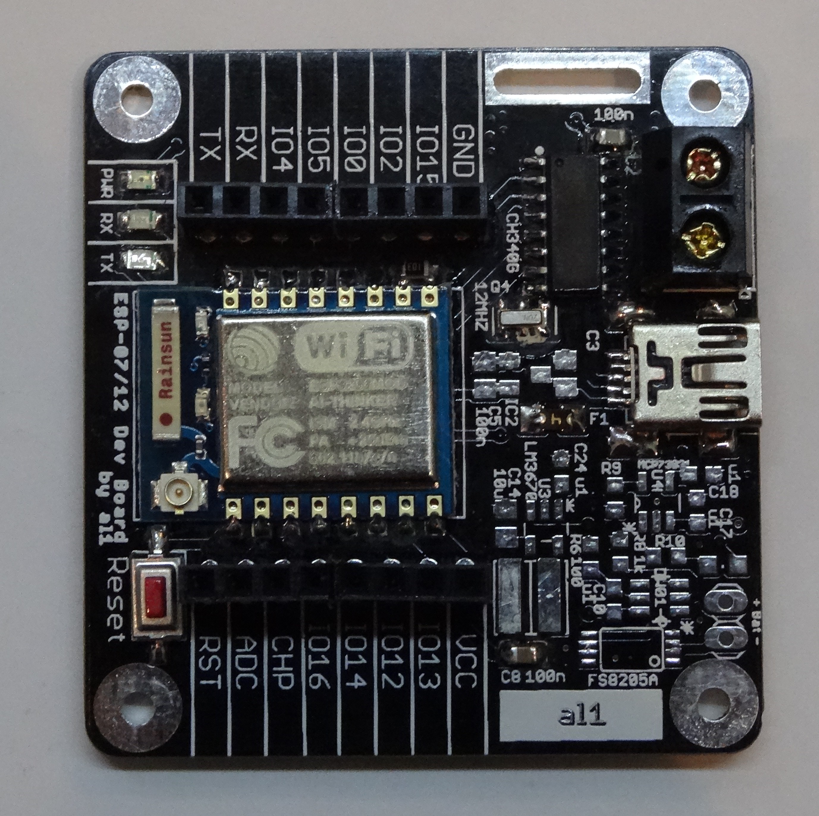
Soldering first PCB!
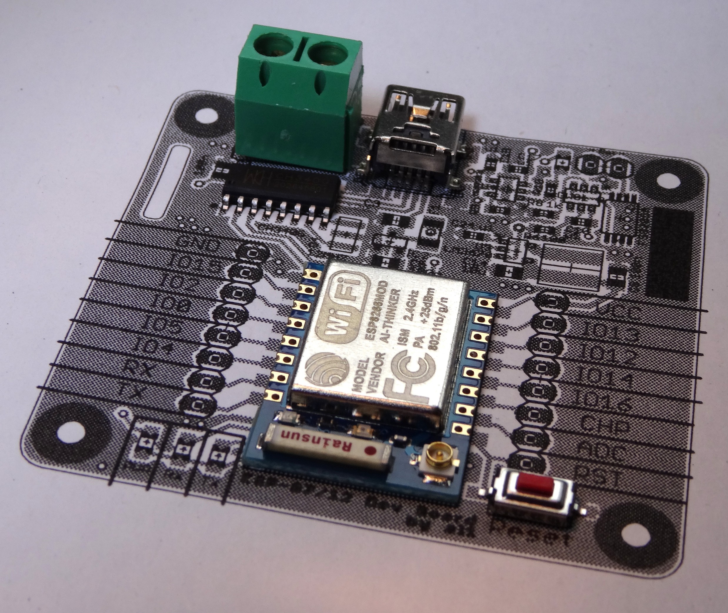
05/16/2015 at 14:58 • 2 commentsI could not wait so I solder the first PCB! I designated SMD solder Jumpers to use these PCBs in different configurations. This first is the absolute minimal configuration: simple LDO and no LIPO-circuit.
![]()
![]()
-
PCBs arrived today!
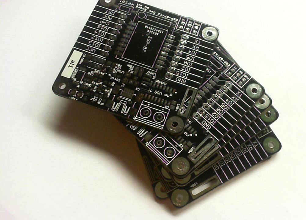
05/16/2015 at 10:31 • 0 commentsThe PCBs I ordered at http://dirtypcbs.com arrived today. Next step will be soldering the first prototype.
![]()
(sorry for the bad image quality, it was made with a webcam)
-
Idea: Prototype shield
04/27/2015 at 20:48 • 2 commentsI do not know yet whether I will make this, but I had this idea last weekend:
![]()
It is a kind of prototype shield for this dev board.
The PCBs for the dev board itself had been shipped today in china. In 3-4 weeks they will be hopefully here.
-
Fisrt Components and paper-test
04/26/2015 at 14:22 • 0 commentssome components have arrived. So I made a placement test on a printed "paper-PCB".
![]()
-
First boards at manufacturer
04/21/2015 at 15:37 • 0 commentsYesterday I odered a first batch of ten board in China. Let's asee how loang they will need.
-
PCB design 2
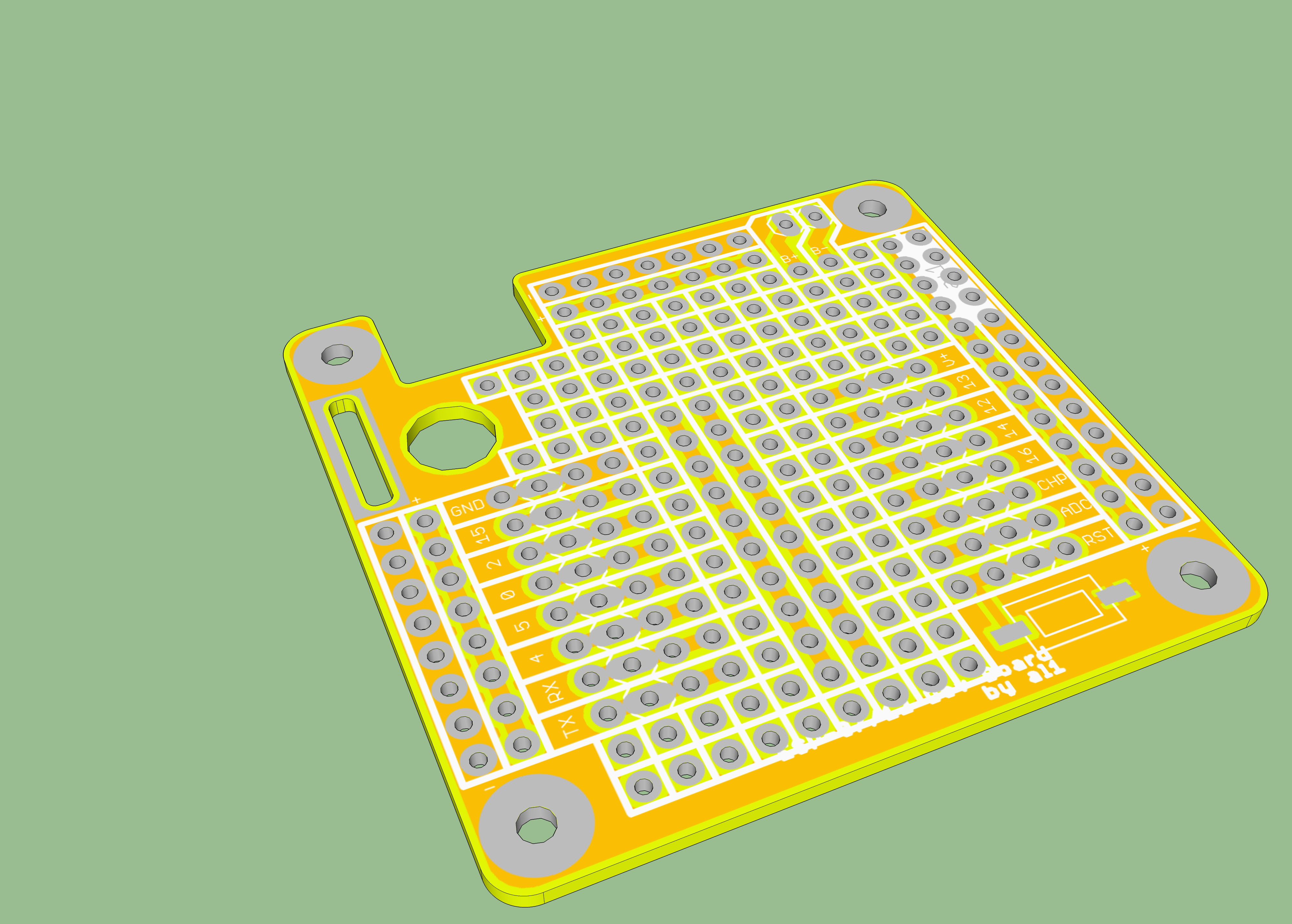
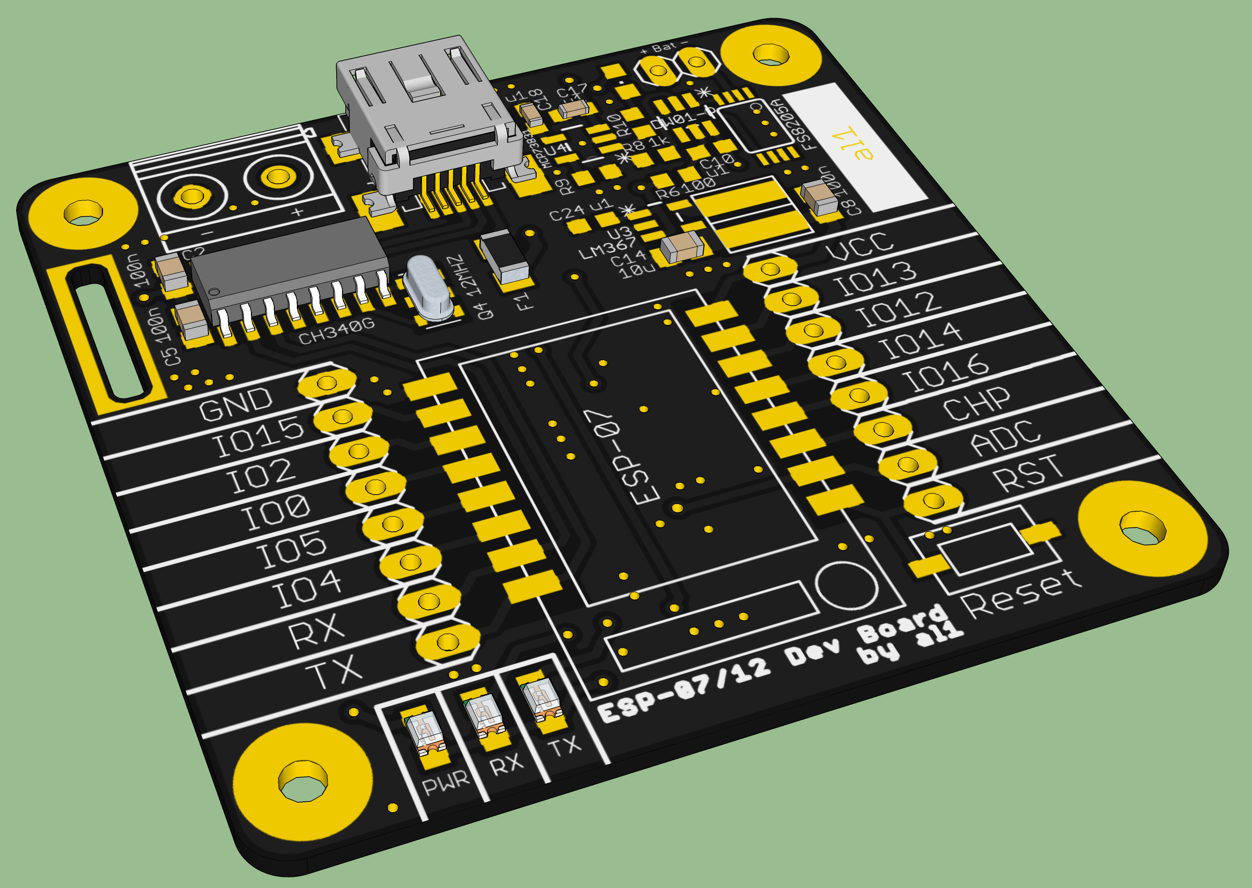
04/19/2015 at 20:09 • 2 commentsI added some parts to the PCB. So here are some new renderings. I Also decided to use black solder mask, this looks better than the red one (perhaps I will change this again, if the black solder mask is too expensive).
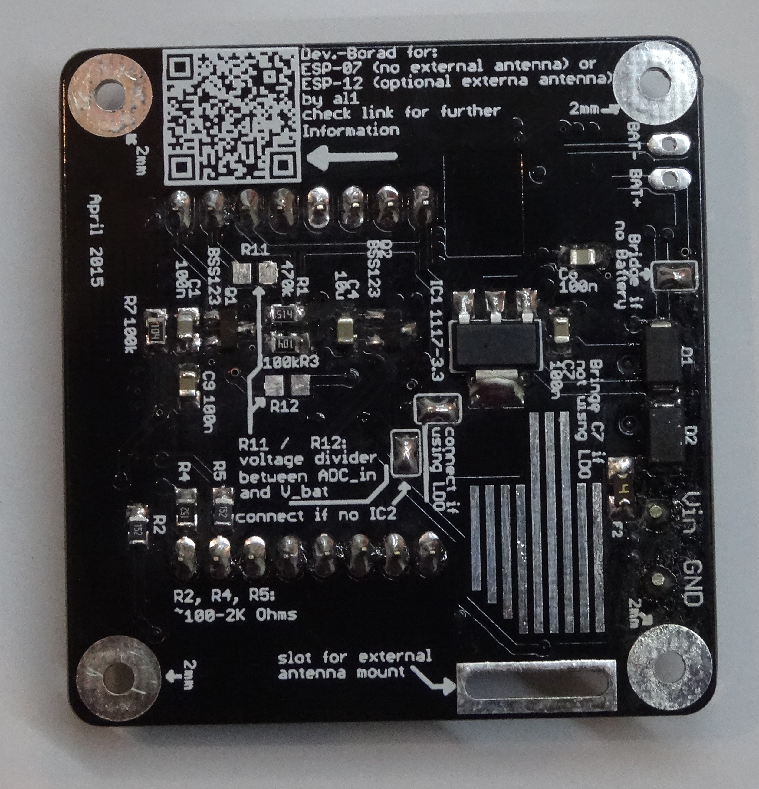
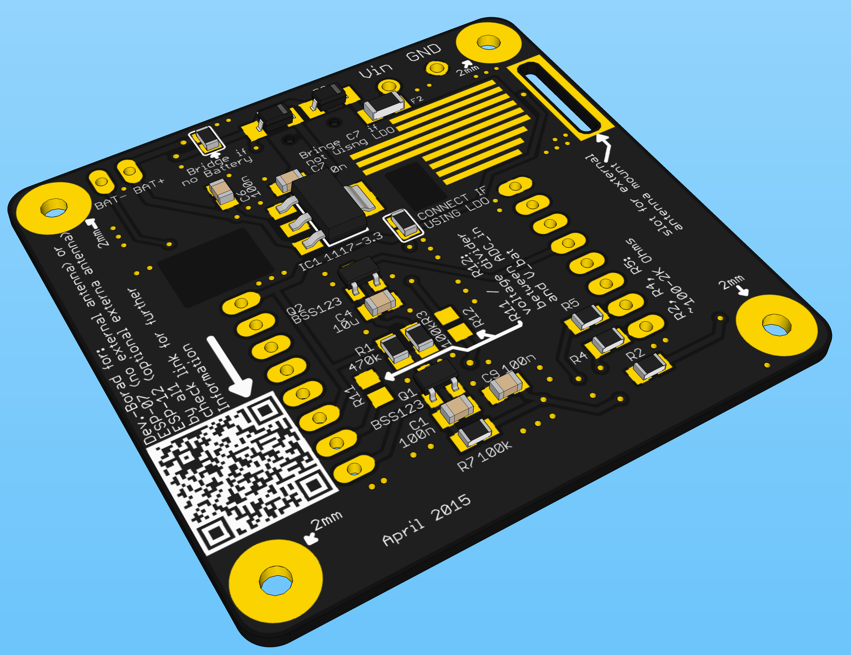
I added some Jumpers for using a linear or a switching voltage Regulator. Also the battery-charging circuit is optional. The renderings show a version with standard LDO (bottom) and no battery circuit.Top Rendering:
![]()
Bottom Rendering:
![]()
-
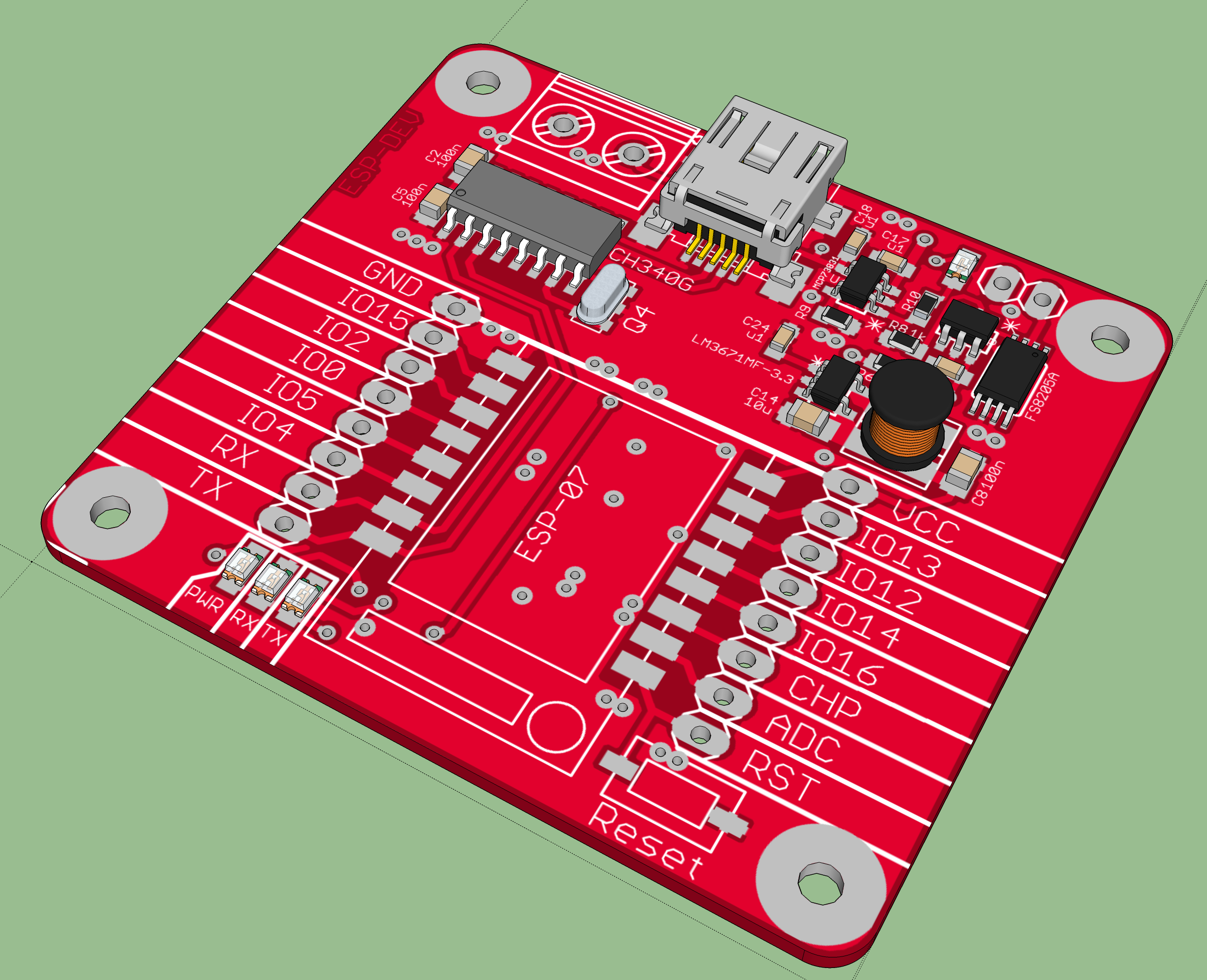
PCB design 1
04/11/2015 at 20:52 • 0 commentsThis is a first Version of the PCB. There are still some parts missing. I will add some reverse current protection diodes in the circuit in the next step.
![]()
ESP8266 (ESP-07/12) Dev Board
PCB for fast development with ESP-07 / ESP-12 with on board USB to Serial converter and on board lipo charge / protection circuit