Savin C2020 Teardown
When life gives you photocopiers...
When life gives you photocopiers...
To make the experience fit your profile, pick a username and tell us what interests you.
We found and based on your interests.
Six of 'em, to be precise:
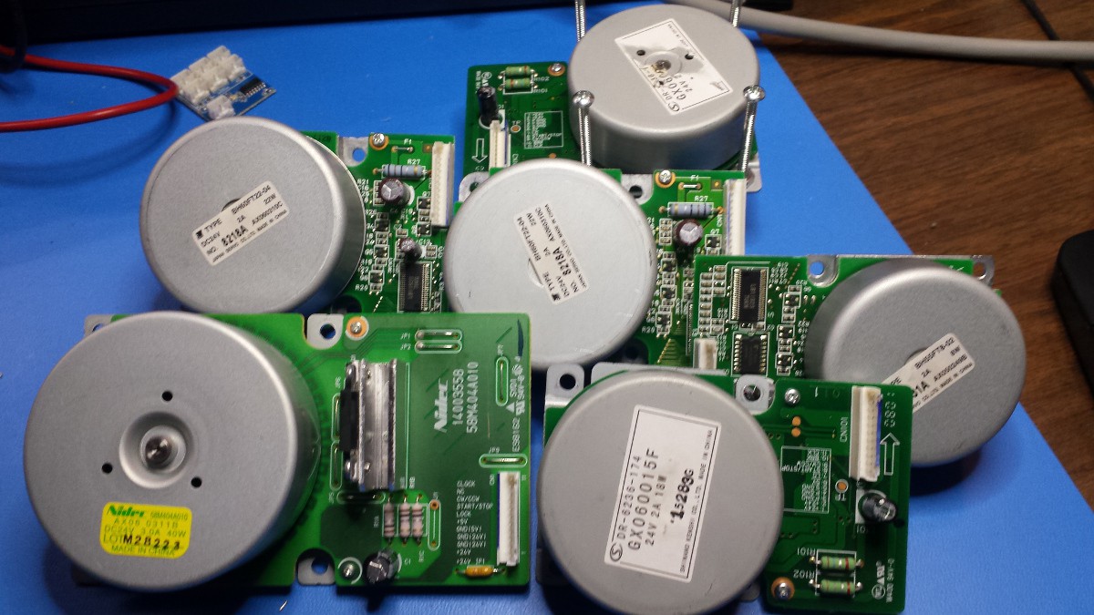
Four different types. I'll address them one by one, starting with the smallest.
24V, 2A, 8W
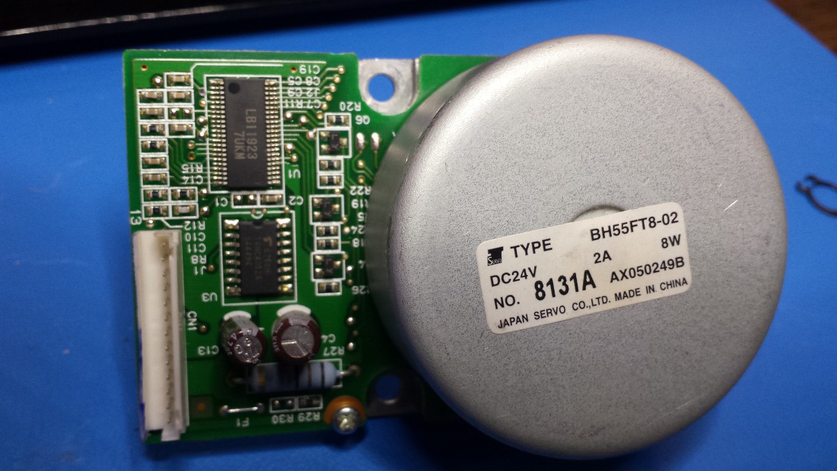
Only one of these motors. It's the only one that has two discrete SOICs, part numbers LB11923 7UKM (the 3-phase brushless motor driver IC) and 74HC4052A, which appears to be an analog mux/demux chip.
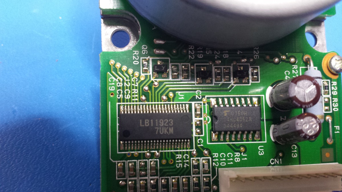
As I'll touch on later, these motors don't like getting taken apart; I can't get the rotors off without getting a bit destructive. However, these vias might be leading up to a few Hall effect sensors:
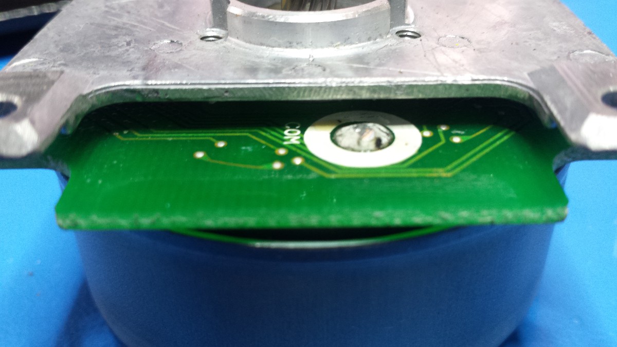
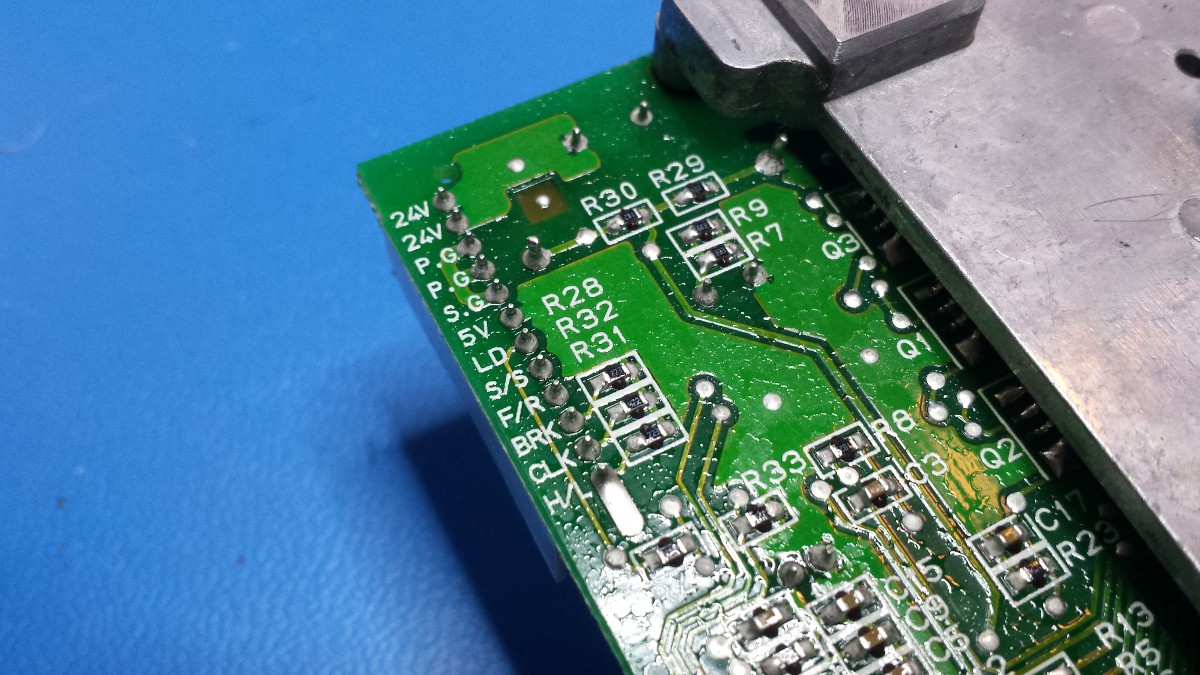
Note the beefy coil connector too--three of these spaced at ~120 degrees, as one would expect. I didn't get a shot of the underside of the board; it's got a lot of discrete components, and the white connector is labeled as follows: 24V, 24V, P.G., P.G., S.G., 5V, LD, S/S, F/R, BRK, CLK, H/L, and ENC.
Shinano Kenshi Co. DR-6236-174 / GX060015F
24V, 2A, 18W
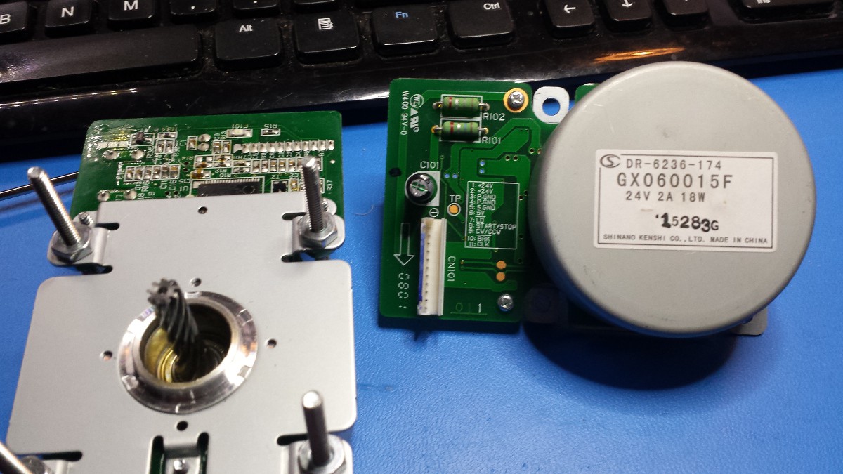
Two of these fellers. The single driver IC on one is impossible to identify; it looks like the label has been etched off or otherwise obfuscated. The other one looks like this:
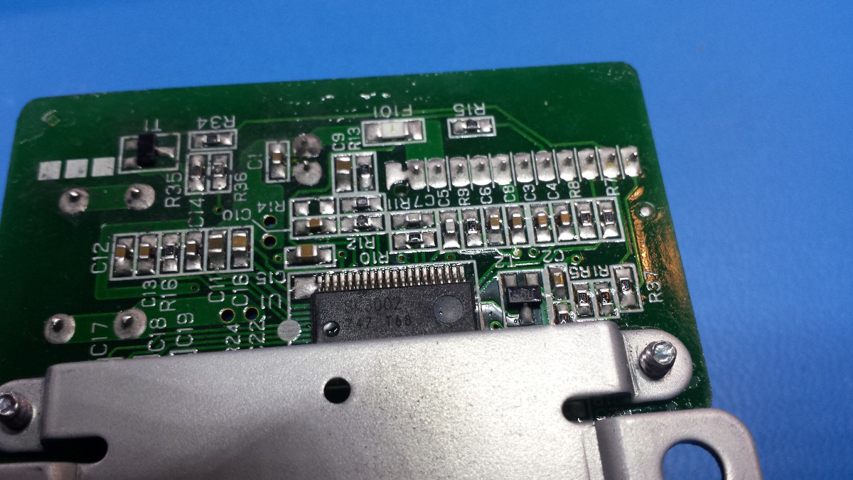
SK3002 747 T68 doesn't bring up any matches. Hell, how do you guys find datasheets online? I keep coming up with really sketchy looking sites.
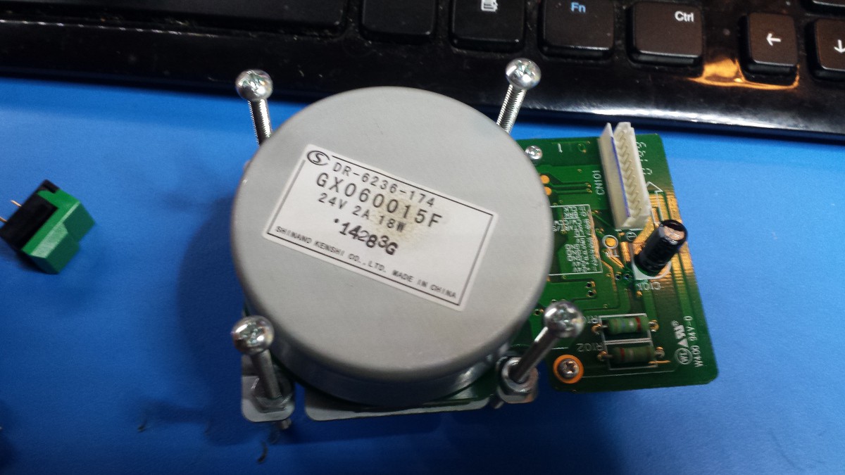
Since I had two of these (and they're smaller than the other pair) I decided to putz around with one of 'em. I used a bit of 6-32 hardware to build a little stand so the motor could rotate freely on the bench. I built up a breakout cable using one of the original connectors from the copier (thank goodness I kept the wiring harness) and fed the motor 24VDC and 5VDC; when I pulled the START/STOP pin high, the motor started twitching. It seemed to twitch once per rotation and would do this maybe 10 or so times before shutting down.
I cobbled together an Arduino driver that allowed me to send a 5V 50% duty cycle square wave to CLK; when I did this and hit the START/STOP with a HIGH signal, the motor responded by spinning at [what looked like] maybe 500-1000 RPM or so. Sending 5VDC to the CW/CCW pin, as expected, changed the direction; I think HIGH = CW, but I could have it backwards. Either way, I didn't figure out what LD or BRK did, and I didn't test CLK above 1 kHz or so.
I also put a bit more effort into pulling the rotor housing off one of these units, starting by removing the label:
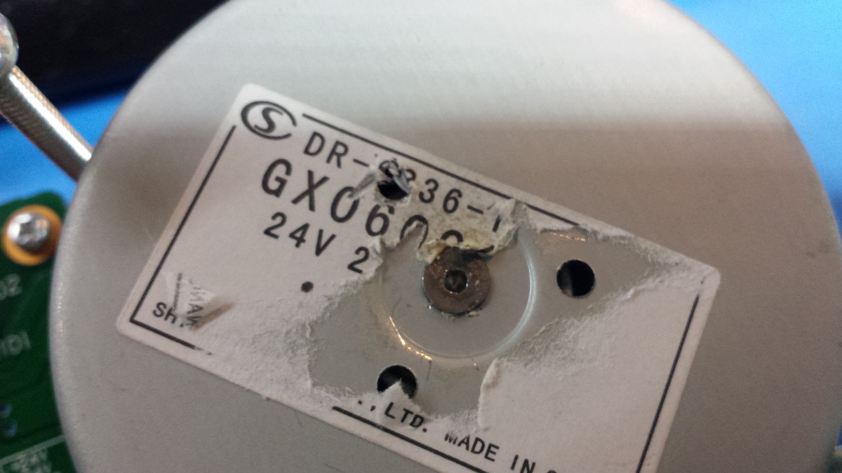
Looks like they assembled the motor and used a press to push a serious divot into the shaft, spreading it out and sealing the whole deal up. I don't think this was a malicious move to keep would-be hackers out; it's just a cheap and effective way to securely attach the rotor (which is presumably lined with magnets) to the shaft. Either way, I didn't want to drill it out so I tried the other side:
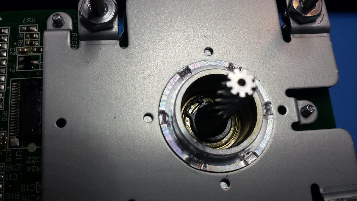
Kinda a funky looking snap ring. I don't have any fancy snap ring tools so I donned safety glasses and popped it off with a screwdriver; however, nothing seemed to come apart despite some pretty serious encouragement.
One other thing to note on these two motors:
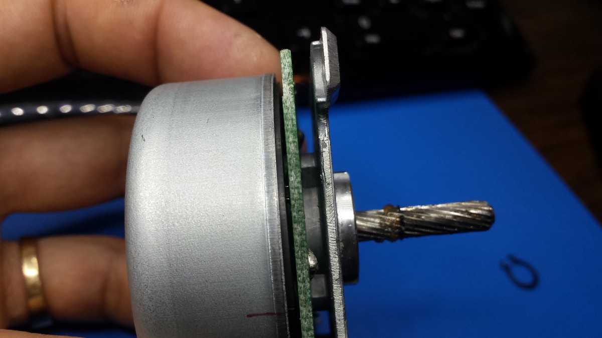
So it's pretty tough to see, but the two lines between the rotor housing and the circuit board appear to be some kind of component. There are a number of identical ones all around the circuit board, too. Maybe a bunch of Hall effect sensors? Man, that would be sweet.
Japan Servo Co. Type BH60FT22-04 / 8218A / AX060310C
24v, 2A, 22W
Two of these guys too. Beefy, with a machined mounting bracket instead of the stamped piece on the previous pair:
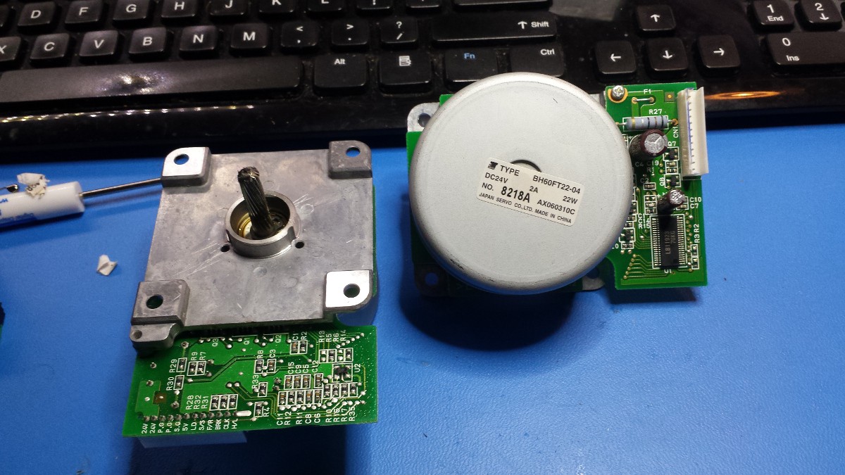 Same driver chip as the smaller Japan Servo Co. unit, but no mux/demux visible (I suppose it could be hiding under the rotor):
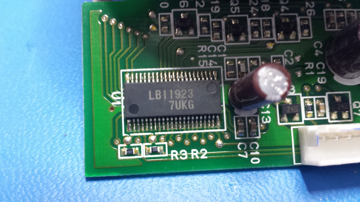
Pinout:
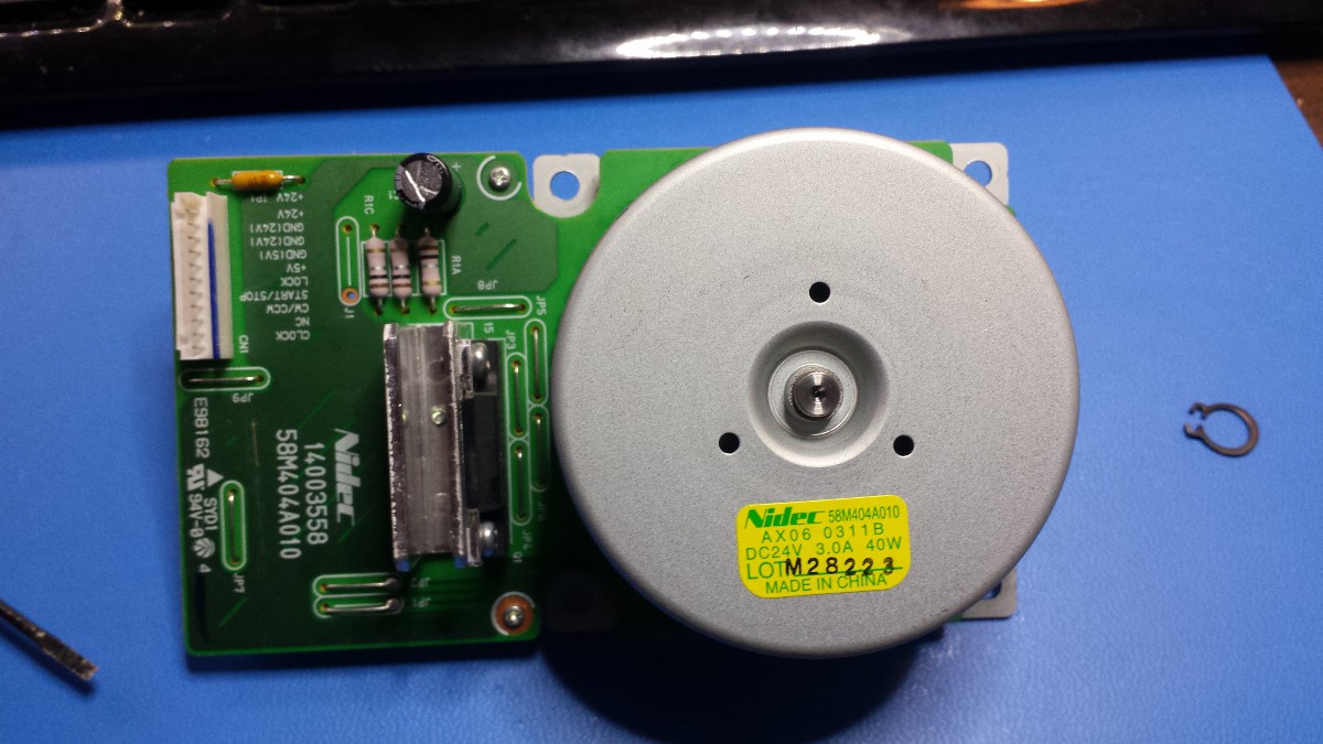
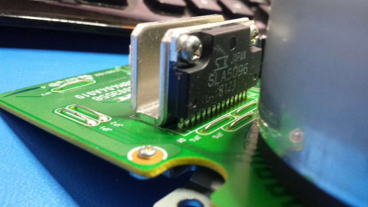
24V, 3A, 40W
This one is pretty beefy.
A bit delayed, but here are the balance of the teardown shots from earlier this month.
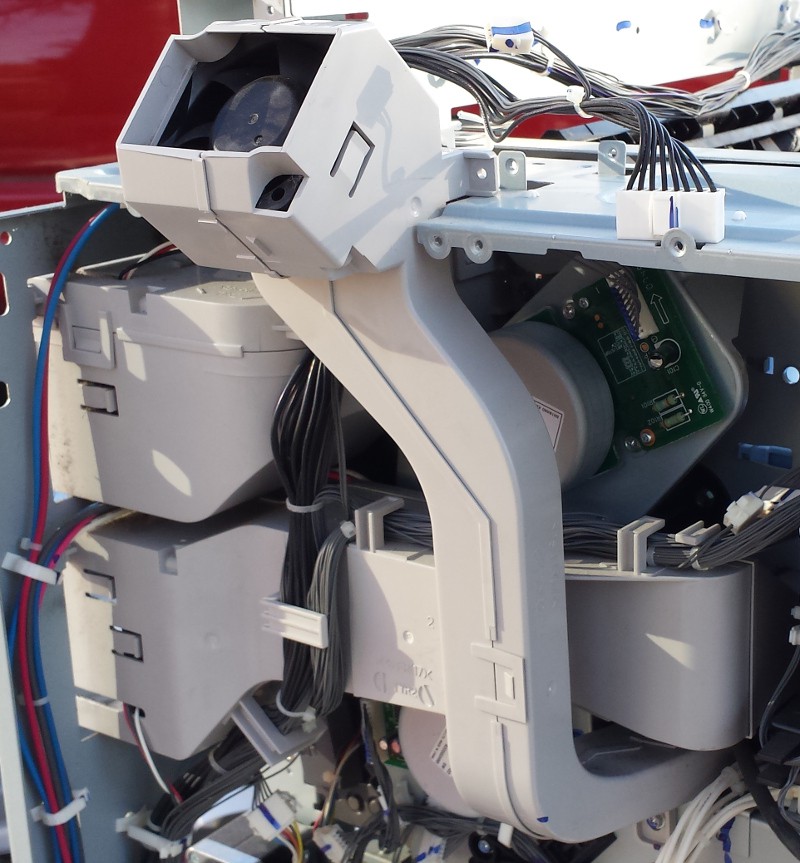
I found a number of cooling fans in various spots; a few of them use hilariously complicated and intricate ducts to direct air exactly where the designers needed it:
The copier uses a number of high voltage (well, somewhat high voltage--low kilovolt range) circuits to charge drums, all provided by this board:
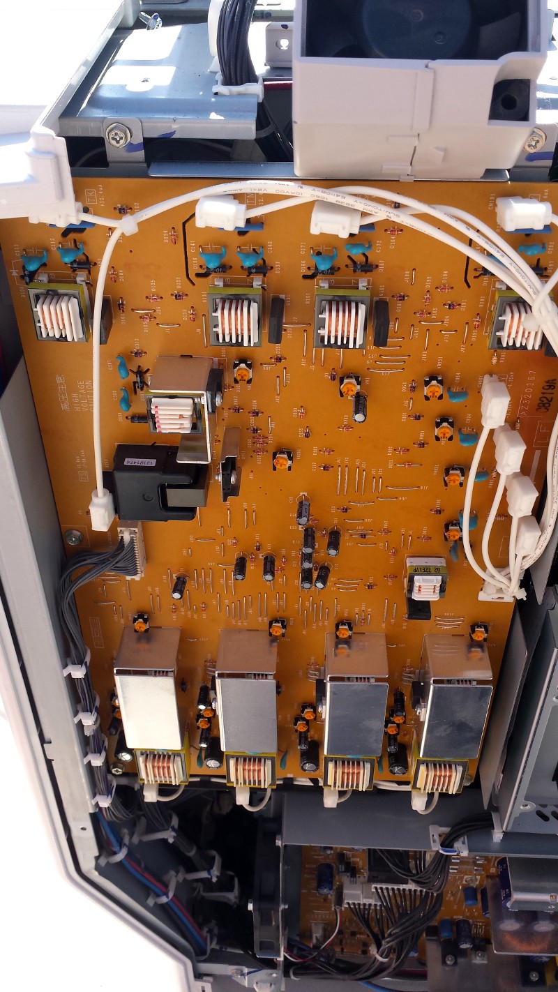
The HV leads run through a molded plastic tray on their way to the drums; here, I've pulled a few of the white leads out of the tray and left others in place:
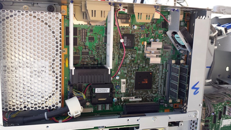
The machine uses a pretty standard looking computer, although most of the chips are Ricoh-branded (apparently Savin = Ricoh). HDD is 40 GB:
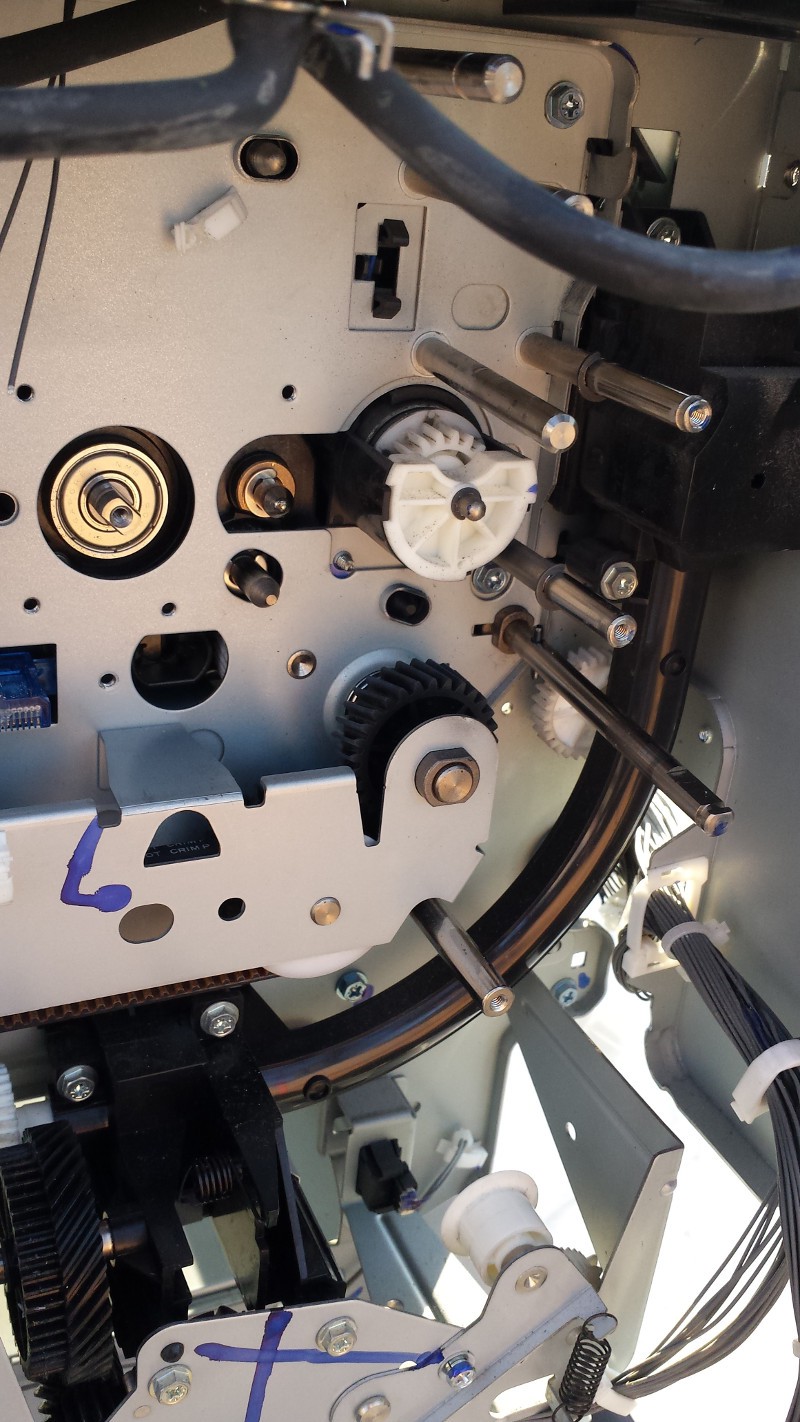
This little curved tube is actually an Archimedes' screw for transporting black toner. Yeah, it pretty much got everywhere... as cool as this part was, it was too messy to reuse. Another interesting note--take a look at all the blue permanent marker scribbles! Tons and tons of these all over screws, brackets, wiring harnesses, and more; I'm guessing they're part of a final quality check at the factory:
Okay, so this is what we all came for: motors. The copier has lots of motors. I'll follow up with a thorough inventory of stuff I grabbed, but you can see a number of digital brushless motors in this picture; they're all pretty heavy, 24vdc, 16-24W, and include small helical drive gears. No datasheets, so reusing them will be a fun challenge:
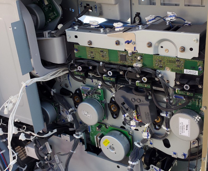
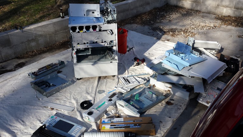
We had some spectacular weather in Minneapolis this past weekend. Definitely the right time to drink a few beers and rip apart a photocopier behind your house. I'll get into the salvaged parts later; for now, these are a few shots I grabbed while disassembling the unit (with italicized comments above each image).
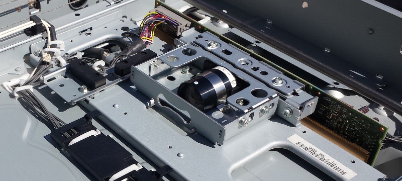
The stationary portion of the imaging system: an excellent lens, a large line sensor array, and a dedicated processing board. Not pictured: a few first-surface mirrors mounted on the moving head.
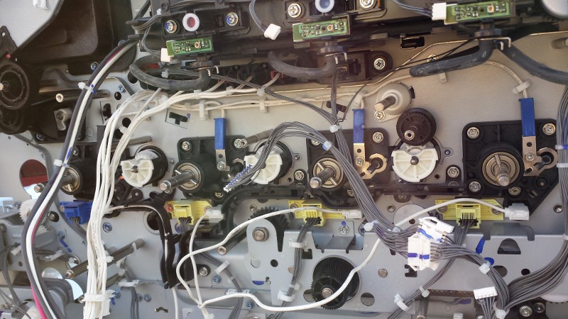
These four sleds accept the individual toner cartridges. They've each got an integrated limit switch to detect insertion, and the cartridges themselves engage with the white gears (you can see the one for the black cartridge) that drive internal augers for toner extraction. Messy, but not as bad as I'd feared:
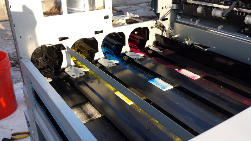
Back end of the previous image, including tiny viewing windows for each toner cartridge. The bundle of white wires in the lower left corner are HV leads for charging various drums and such; the smaller circuit are (I believe) some kind of toner detector for the low toner warning system:
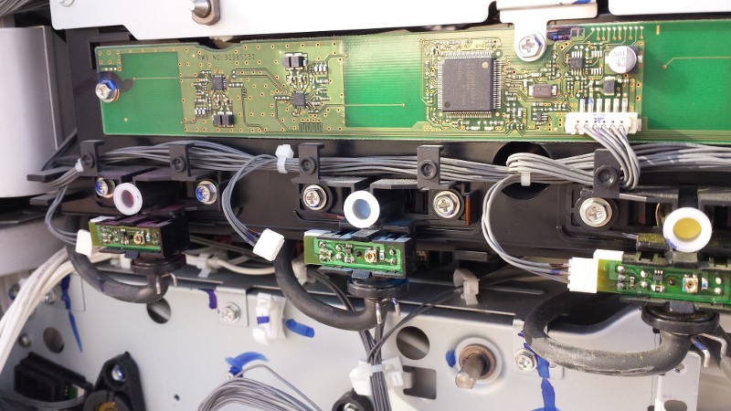
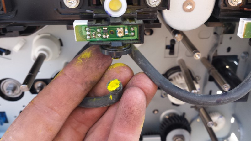
I got curious and pulled one of the rubber hoses off; I assumed they were air lines for something, but I didn't expect it to be packed with toner. This has the look of a plugged pneumatic conveyance system, but I can't imagine that working reliably with rubber hoses. Any ideas?
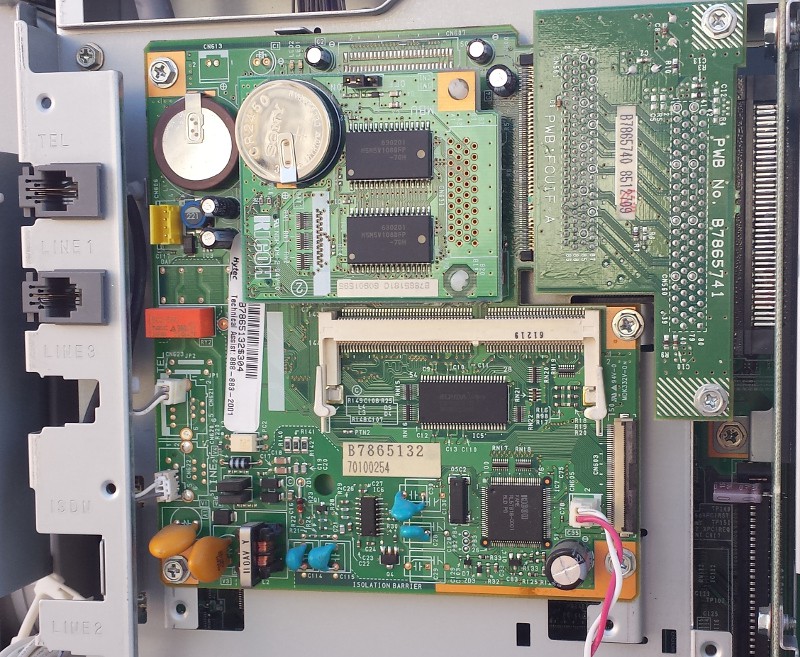
Ah, the pinnacle of 90s innovation: the integrated fax machine. This subsystem features 2 (!!!) backup batteries, as well as a crappy external speaker (connected via the white and red wires) for classic fax machine sounds:
A fine day's work:
More to come!
Create an account to leave a comment. Already have an account? Log In.
Ah, that makes a lot of sense! I ended up avoiding a decent amount of the toner system just to avoid making a huge mess. How much toner did the copiers you worked with typically waste? Did they ever recycle from the jug to maximize toner cartridge life?
Did you work out what those tubes filled with toner were for. The top part of the thing it connects to looks like an opto-interrupter and the bottom almost looks like it has a piezo element in it.
I think I grabbed one of the sensor boards; unfortunately I had to recycle a lot of the stuff related to toner before bringing it all inside. I'll look through the bin though.
I've seen 2 or 3 old copiers lying around at the university campus along with old microwave ovens, crt screens and old PCs. Wonder if they'd mind me taking some of them......
Oh yeah - I did this with a large 90's era Xerox machine back about 10 years ago. SO much good stuff inside - and I saved a lot of it. Even so, the inner chassis was had to be "compressed" with a sledgehammer to fit it in the dumpster.
I love projects where the sledge turns into a legit tool. I actually found an outfit that came by my house on Sunday to recycle the 200 or so pounds of crap I didn't want to keep. It wasn't the cheapest option, but I got 6 hours of entertainment plus a huge bundle of parts out of the deal. More pictures to come!
My guess - 95% plastics. I worked in a copy shop for a while, those machines are rebelling beasts from another dimension enslaved by canon and others to print, copy and scan documents. Any plans for the parts or hacks for retrofitting in mind?
I'll post more updates down the road, but this was mostly a learn-a-bit-more-how-it-works and salvage-stuff-i-might-need operation. I've gotten rid of most of the chassis (metal and plastic, mostly) and saved the goodies: a number of PCBs (including a big 2kv power supply board), tons of gears and bearings, 5 stepper motors, 6 big brushless motors with integrated drivers, some nice first surface mirrors, a really nice lens... it was a great day.
I'll probably try to use the bits in some robot project down the road. Lots and lots of IR sensors too, plus a number of small gear motors. So many mechanical bits! Like I said, I'll post a more detailed update with some salvage inventory pictures later this week.
Hah! I think the de-facto method for tearing-down a photocopier these days involves a bat and a big field... but I wouldn't be able to do that, and I'm glad to see you're not either.
Yahknow "Johnny Five" from the movie Short Circuit, his eyes were photocopier lenses... can't remember where I read that.
Become a member to follow this project and never miss any updates
I used to be a savin tech, but only for b&w machines. My educated guess for the black hoses is that they are for waste toner. There was most likely a jug somewhere where they terminated.