-
smd version
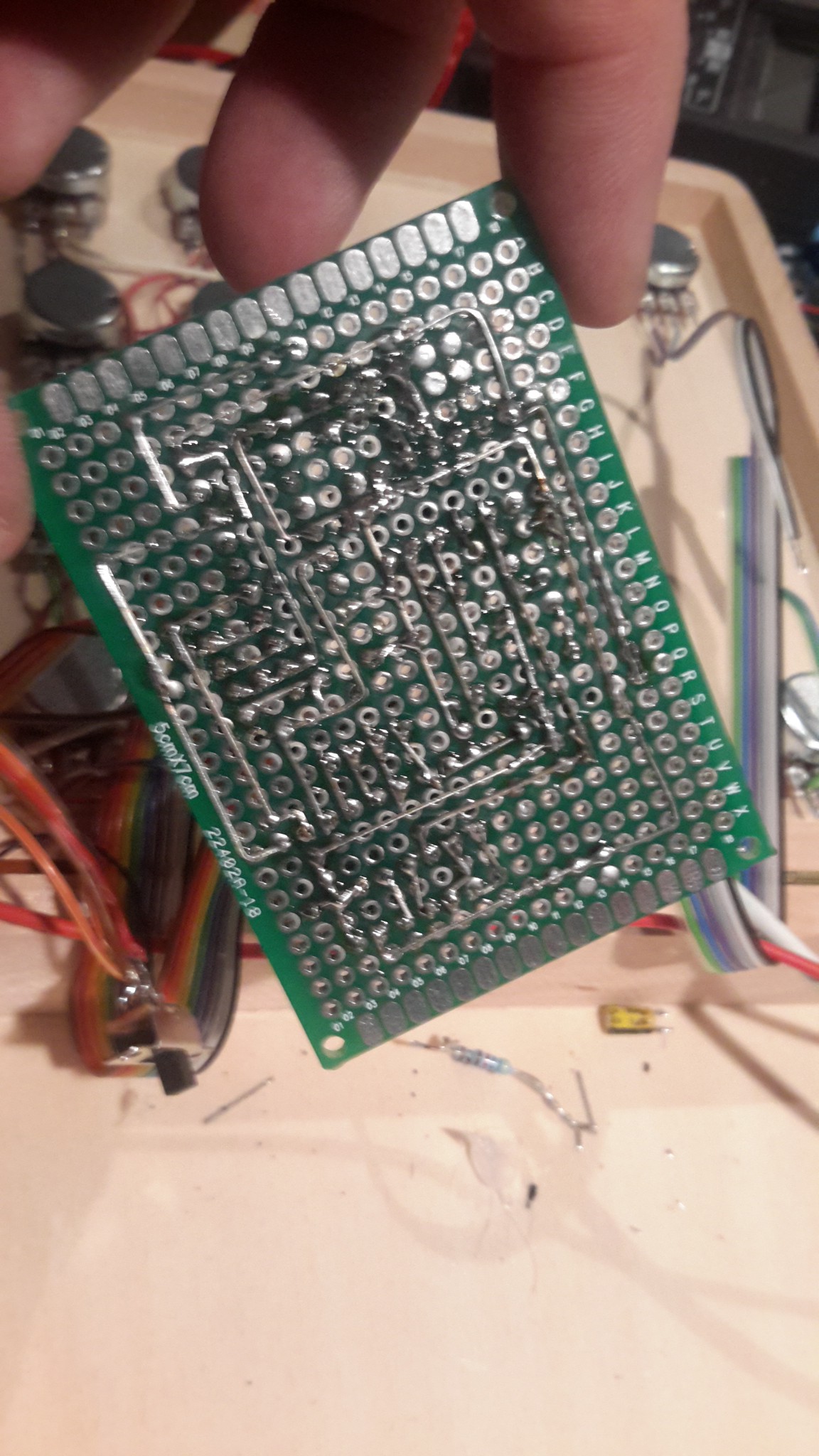
07/11/2017 at 21:42 • 0 commentsI came around to design an SMD version of the perfboard version :)
On board is:
- 8ch LED port
- 8ch potentiometer port
- counting up/down switch
- octade (binary) / decade switch
- synced pitch switch and potentiometer
- speed potentiometer
![]()
![]()
-
a little upgrade
02/04/2017 at 23:23 • 1 commentI've bought one of those cheap LM386 DIY kits on eBay and upgraded Zynthia to be fully stand alone. I only had 10 red caps for the resistors, so I took green instead and a dymo label, the last switch is now the power switch :) I also mixed up one power cable and without checking I've almost killed a battery by shorting it :D
http://www.ebay.de/itm/272323639604?_trksid=p2057872.m2749.l2649&ssPageName=STRK:MEBIDX:IT
![]()
![]()
-
4028 - installed
04/26/2015 at 19:03 • 0 commentsSame colors for knob and led cables. Yay. Not sure what it is this time, but the BCD mode gets funky when it's going down. Anyway - I haven't posted a pic from the inside for a while.
![]()
I can't find a mouse to edit a video in blender on a mac, so the ring modulator video has to wait a bit... but here's a video of the working 4028. And yes, my calculator recorded this! (well no, you got me, it id not)
Found the mouse, it's rendering!
-
4011 - ring modulator
04/24/2015 at 21:25 • 2 commentsUpdates
2015-04-27 video added
I totally like this stuff more and more! I found a ring modulator circuit built with a single 4011 over here: http://www.diystompboxes.com/smfforum/index.php?topic=90804.0
I plan to add a frequency divider / D- flipflop made out of a second 4011 to auto sync the modulator, with no clue how it will sound or if it will work.
http://www.electronics-tutorials.ws/counter/count_1.html
Makes me want to buy an oscilloscope.
Here's the D-flip-flop in NAND gates turned to a T-flip-flop, which I didn't use because reasons - taking the 4017 instead.
http://www.neuroproductions.be/logic-lab/index.php?id=40498
Thanks to @haydn jones for sharing his #Open 4,4 Sequencer
-
hardware vs. frequency
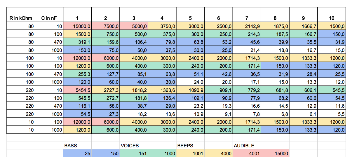
04/23/2015 at 13:57 • 2 commentsI've made a table to see the frequency range of the potentiometers vs. capacitors in 10 steps and categorized them to see what values make sense for what spectrum/range.
![]()
-
painted the box
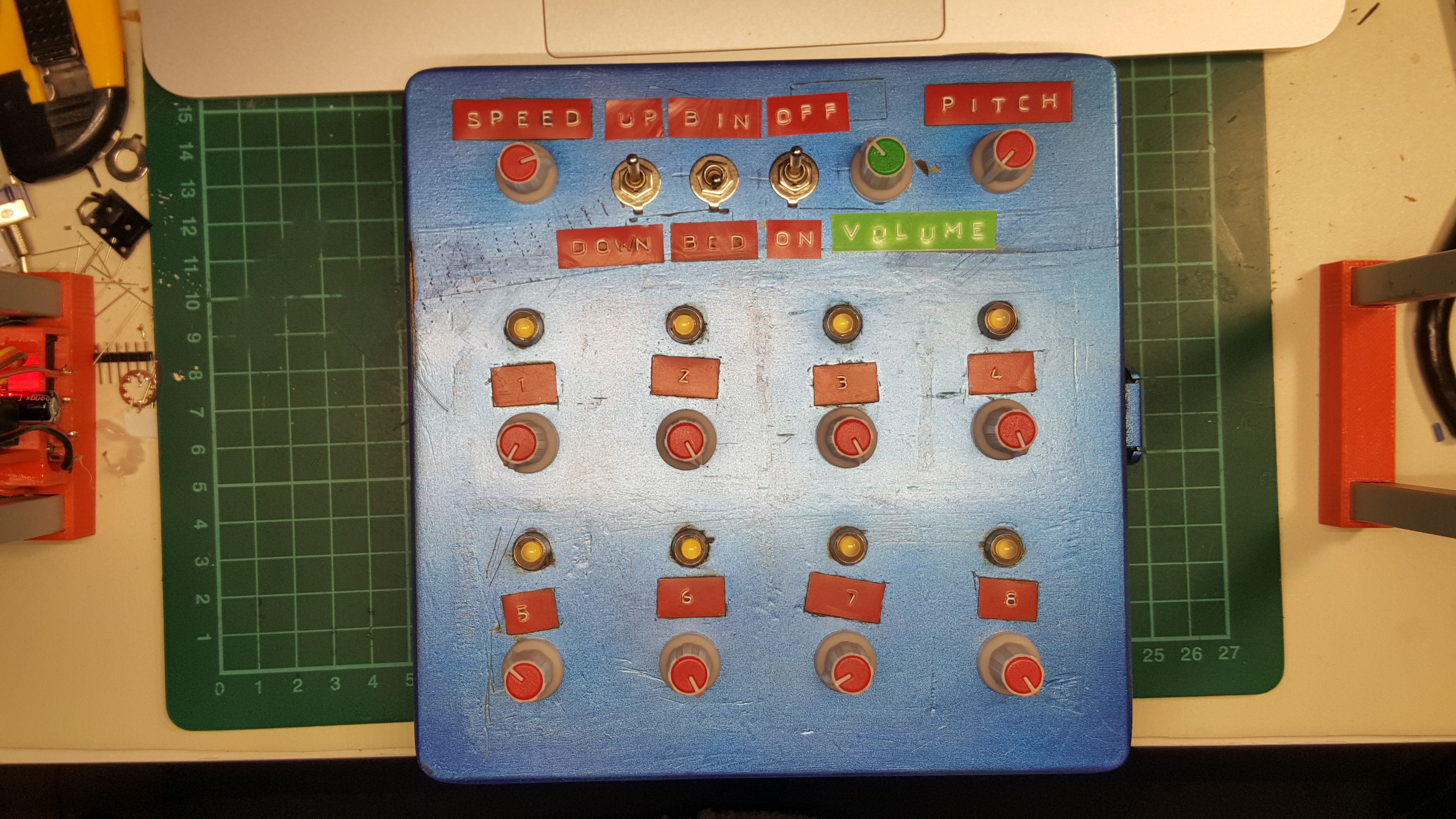
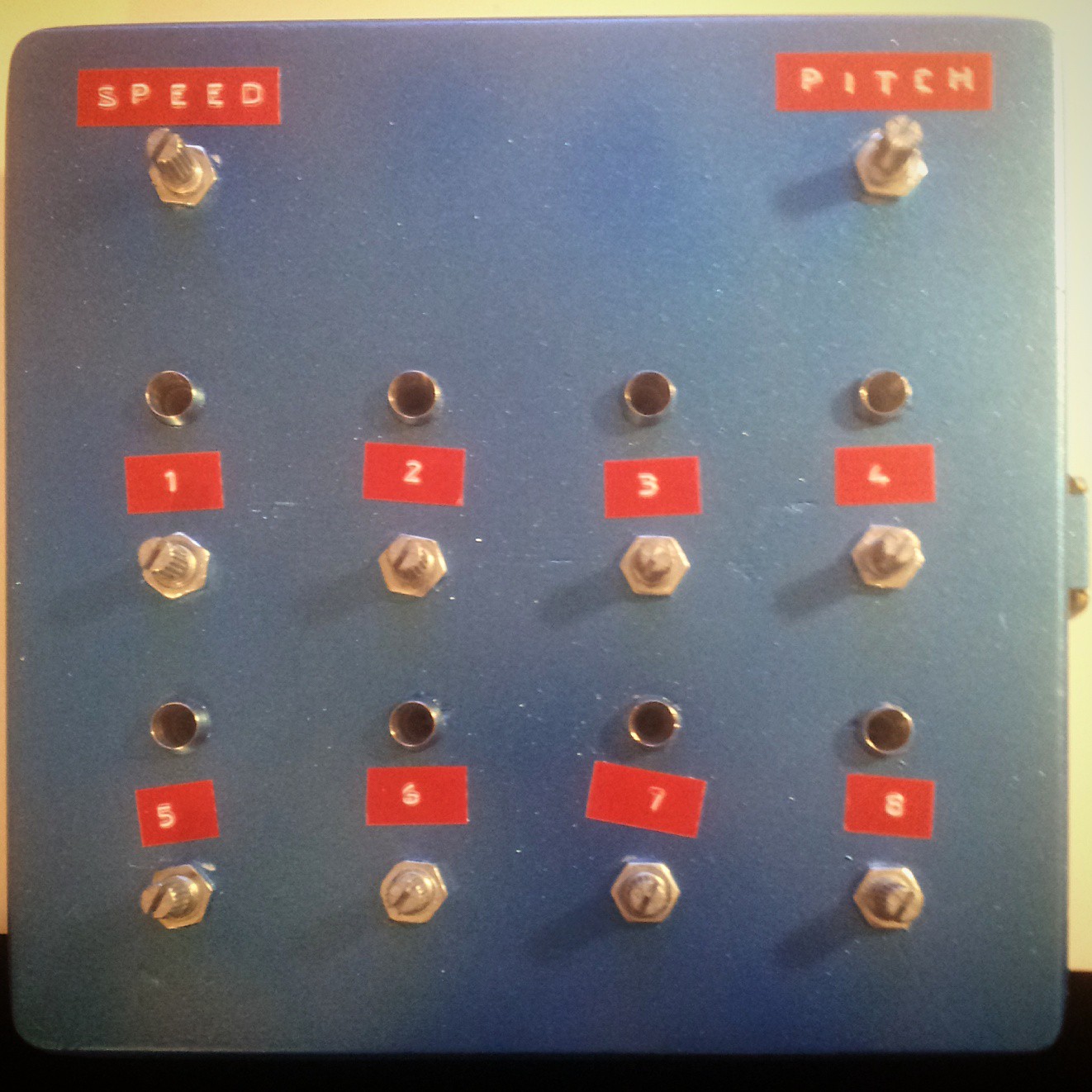
04/21/2015 at 20:25 • 0 commentsI was in the mood for some spray paint fumes and since I wanted some LEDs I had to add some holes and the golden print was drilled through etc. so I made the box metallic blue - that's also the color of my guitar, my FX pedal and my loop station - so it will fit right in some day ;) I had no dymo labels in black left, so I took the red ones. Heavy contrast and all, but with the "oil paint" weathering makes it look really really great. Only the up/down and bcd/dec switches are missing and I will have to make the DC and output plugs going somewhere. I drilled a hole for the DC plug and almost ripped the box apart but was able to glue it back together. Here's a "not weathered" picture:
![]()
-
You get what you've paid for
04/21/2015 at 18:50 • 0 commentsIt's not that important, but when I noticed that one tone pot was off in the lowest position I decided to measure the 100K potentiometers I've bought for 2,10 Euros. Here are the values:
1 2 3 4 5 6 7 8 9 10 102 101 100 91,8 91,4 91 90,7 90,6 88,8 82,9 2% 1% 0% 8,2% 8,6% 9% 9,3% 9,4% 11,2% 17,1% Look at these percents! I've ordered some more to get equal values. But I guess that was what to expect :D
-
Next step: add a russian 4028
04/19/2015 at 18:23 • 0 commentsYes, I need LEDs! And it turns out my dad has also some 4028s in his drawer which will be great for lighting up the channels! Loot woot! The russian version is called k176id1. I might rewire the potentiometers at one point, they are arranged a bit weird.
Current setup:
1 3 5 7
0 2 4 8
planned setup:
0 1 2 3
4 5 6 7
Or not.
-
I need some help - Nevermind :D
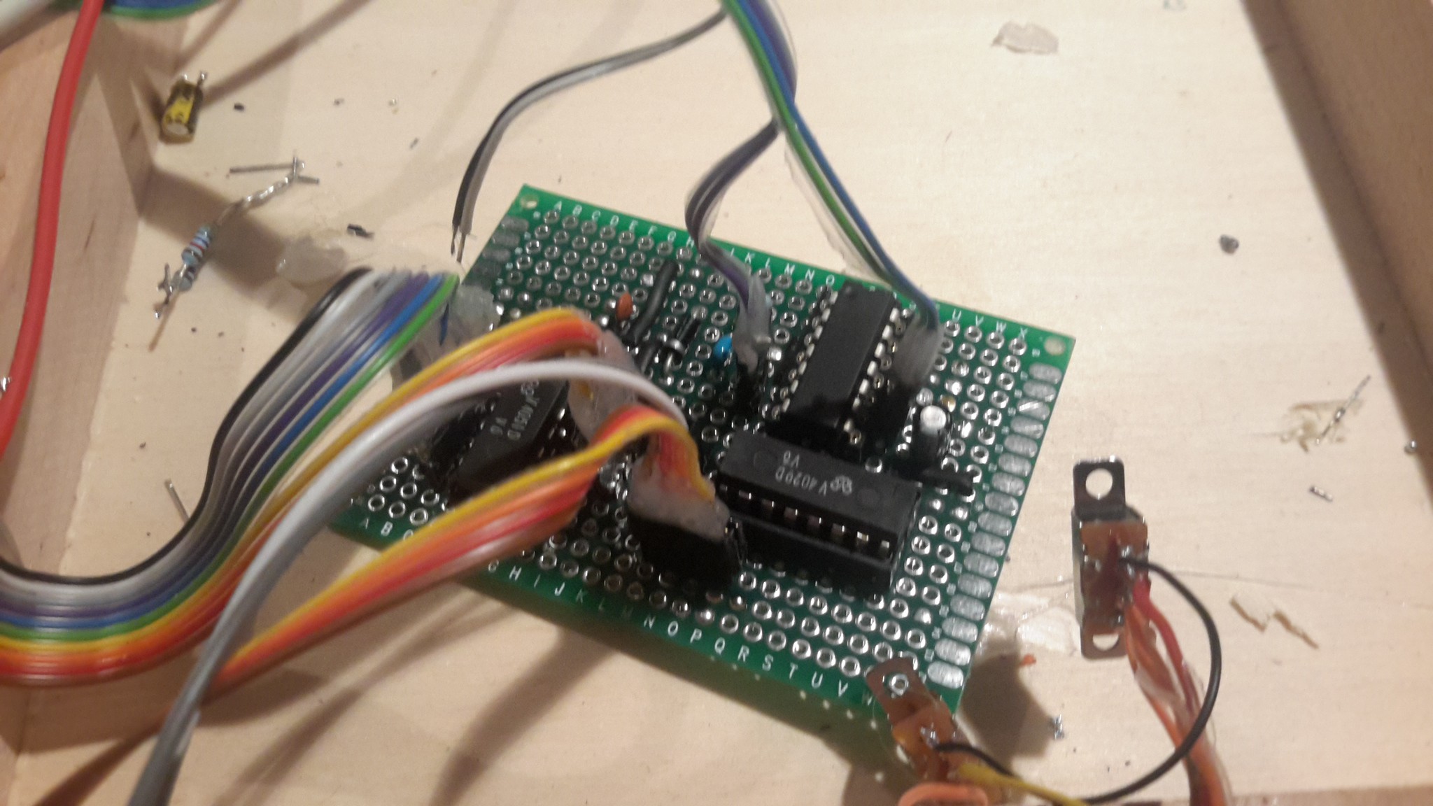
04/19/2015 at 17:52 • 0 commentsThere are 2pins of the CD4029B that I've each connected to a SPDT switch allowing me to toggle between HIGH and LOW. The weird part is that when they both are connected to VCC the 4029 stands and when both are connected to GND the whole circuit turns off. Anyone any ideas?
There are schematics out there where GND and/or VCC go directly to the pins and I found one schematic where there are switches with 47k pull-ups for 9V. I've tried 10k for my 5V set but the 4029 wouldn't switch the channels of the 4051 anymore.
Or maybe it's just broken.
Fixed: I feel so stupid.... so what could it possibly be, if it only works when GND AND VCC are connected to the pins? I haven't connected the circuit to my GND connection, so the 4029 did that when I had my selections made... now I can switch forward and back and from binary to decimal. wooohooooooo!!!!!
Here's a picture of what I had to debug, it looks all the same after a while...
![]()
![]()
-
Now it's only a quintinverter
04/17/2015 at 22:44 • 0 commentsTurns out I've burned a port of the 40106 while switching the capacitor for the 4029 clock signal - why haven't I pulled the ICs out of their sockets, you ask? Because reasons. I didn't think of it. Stupid me. I found a good page for values of the capacitor matching the frequency range I wanted in combination with the potentiometer I had. 10uF vs. 100kOhm.
zynthia - sequencer synthesizer
using a 40106, 4051 and a 4029 to make some noise, following the Logic Noise series on the blog
 davedarko

