Lukasz
-
dev board project moved
06/23/2015 at 20:20 • 0 commentsMoved the dev board to its new home @ http://hackaday.io/project/6417-dev-board-for-nrf51822-core-board to reduce clutter.
-
more goodies
06/23/2015 at 14:12 • 0 commentsFew days ago we got a message from Mike that we won some more goodies from Hackaday. We got Stickvise! and Teensy-LC board.
![]()
Vise will definitely be of great help and assistance with the dev boards! Looking forward to solder them using Stickvise!
Once we kick-off properly we will definitely buy more! Get yours and many more @ store.hackaday.com
-
treats from Hackaday! Yay!
06/17/2015 at 10:24 • 0 commentsSome time ago we received a OSHpark coupon from Mike. We have designed a customised dev board for our BLE board. Fiddling with connectors and wires on a breadboard is just a waste of time.
We only received them yesterday! SWEET!
![]()
Many thanks, this will definitely speed up development and reduce frustrations with those bloody cables.
Eagle files available here.
-
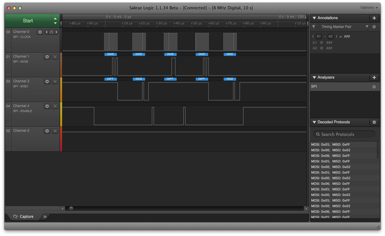
it's alive !
06/11/2015 at 10:25 • 0 commentsThe components are responding! We used a logic analyser with Saleae software to check for I/O digital signals and decode them on SPI.
FM25CL64B Fram tests:
![]()
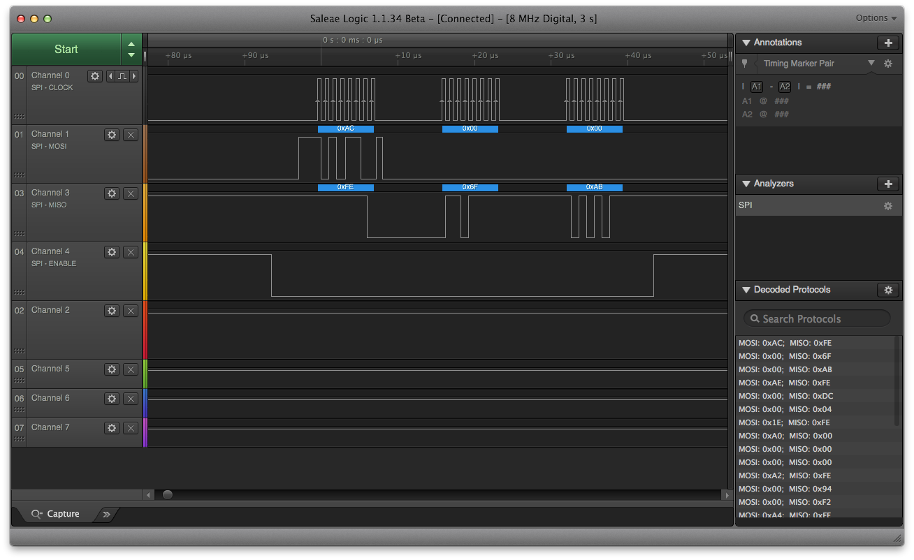
MS5803 pressure sensor tests
![]()
But there were problems of course. Main ones we had to overcome:
- Bypass connectors helped in fixing the wrongly designed layout for W25Q256FV flash memory module.
- Apparently pins P0.26 & P0.27 for the nRF51822 are by default used for the 32kHz crystal. These we used for SPI communications, so again we had to solder bypass connectors. Pins P0.28 & P0.29 worked great instead.
- We did not connect VCCIO from the ADXL362 accelerometer near C6 capacitor, hence another bypass was required.
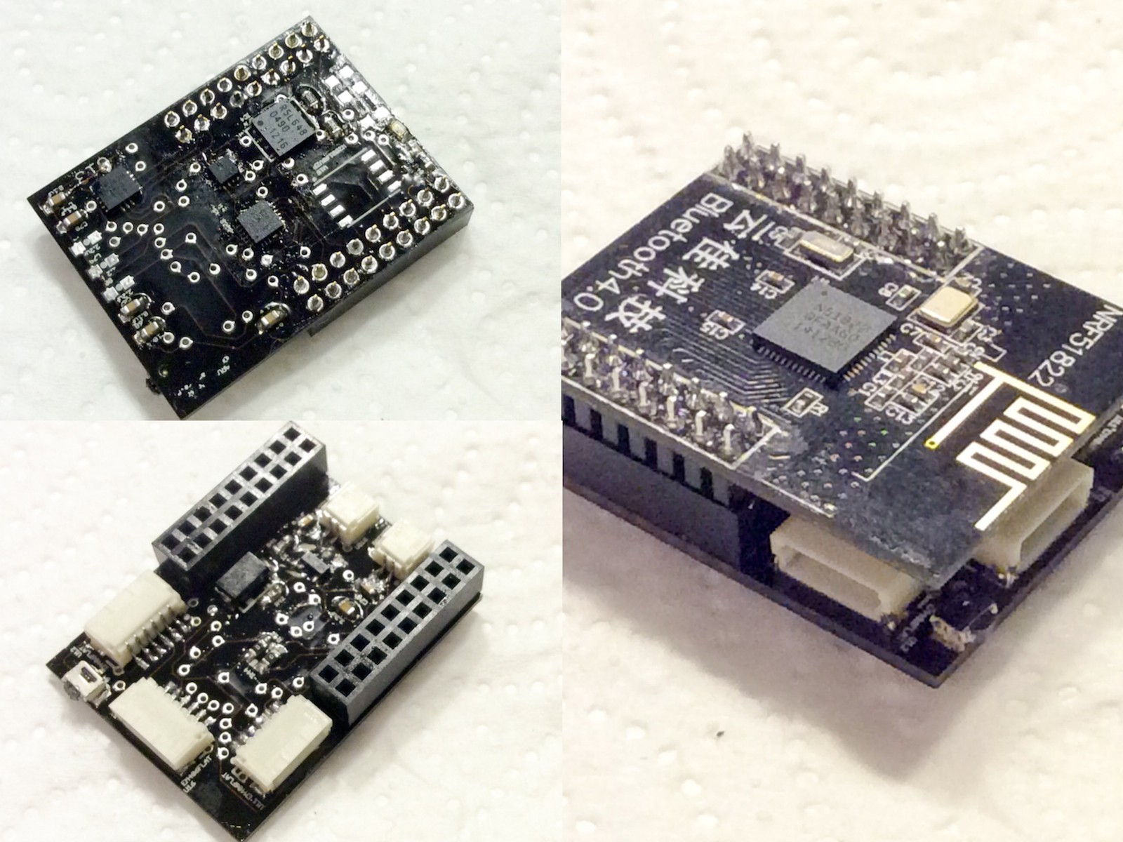
So looks like it's all working! Phase 6 & phase 8 are DONE.
-
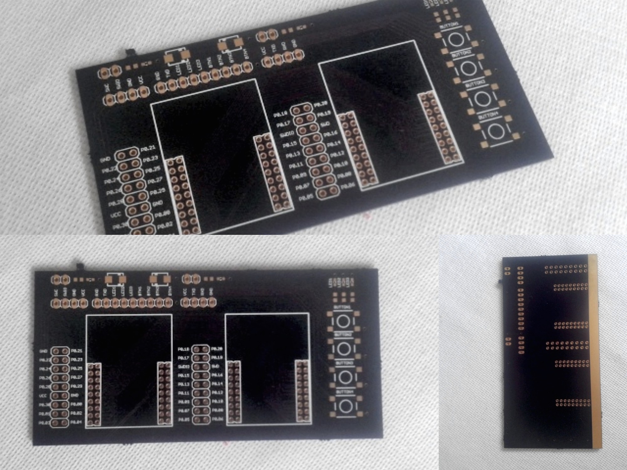
soldering. the physical part
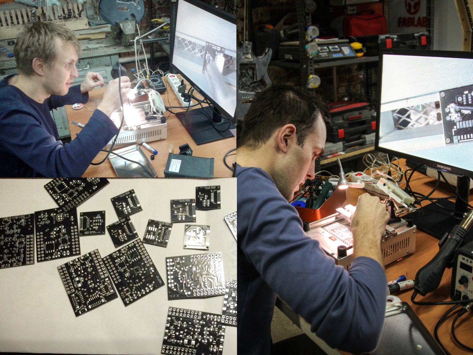
05/31/2015 at 20:43 • 0 commentsSo we got our boards manufactured and delivered just before the weekend. We decided to visit our local fablab in Lodz to have enough space and non-disturbed time to get this over with. Unfortunately time flies and we only managed to solder one 9+DOF board and a few smaller ones with MS5611, MS5803 and BMP280 pressure sensors.
![]()
nRF51822 board fits perfectly, but we also found a flaw on our PCB. Seems like double checking board design isn't enough. The W25Q256FV Eagle layout we found somewhere on the internet does not match the physical part. We haven't soldered this component and will have to make bypass connectors. :-/![]()
Now for the test phase ...
-
finally becoming tactile
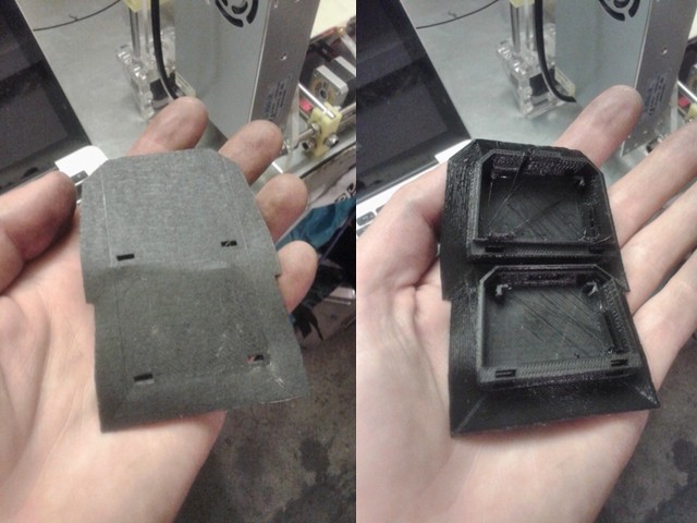
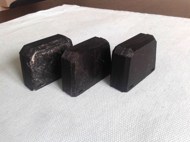
05/25/2015 at 09:38 • 0 commentsWhile waiting for PCB manufacture we decided to move on. We 3D printed previously designed cases and were surprised they fit together quite nicely. Obviously the rough edges had to be ground with a sandpaper and a small file, but hey ... 10 years ago this would not be possible in a garage :-)
![]()
![]()
Our print profile used in Repetier 3D printing software can be found here.
-
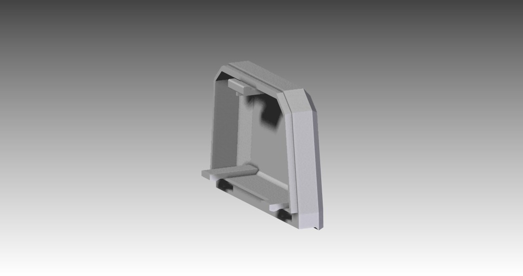
case design
05/24/2015 at 10:30 • 0 commentsWe designed two custom enclosures:
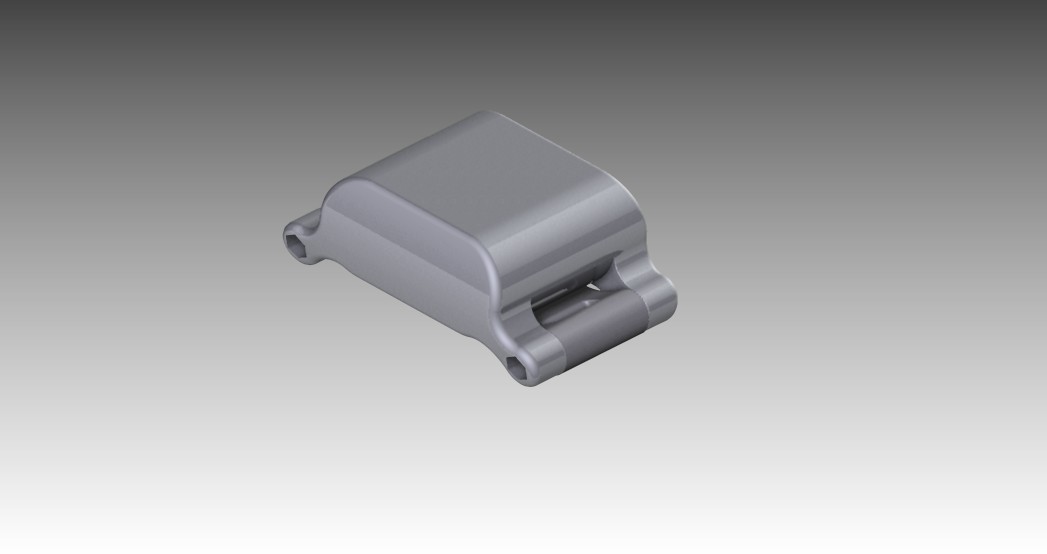
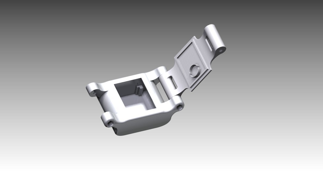
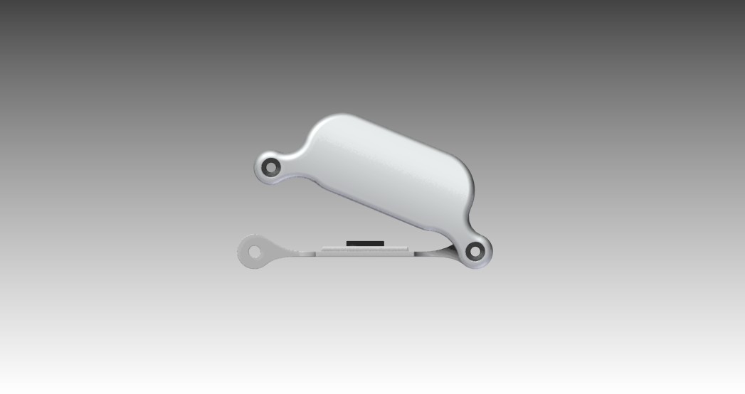
- a waterproof case to be used with a strap - much like a watch, but can be connected to anything really.
![]()
![]()
![]()
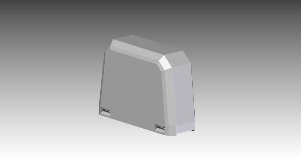
- a highly splash proof case for mounting on a bicycle chain stay.
![]()
![]()
![]()
STL files for 3D printing can be found here.
-
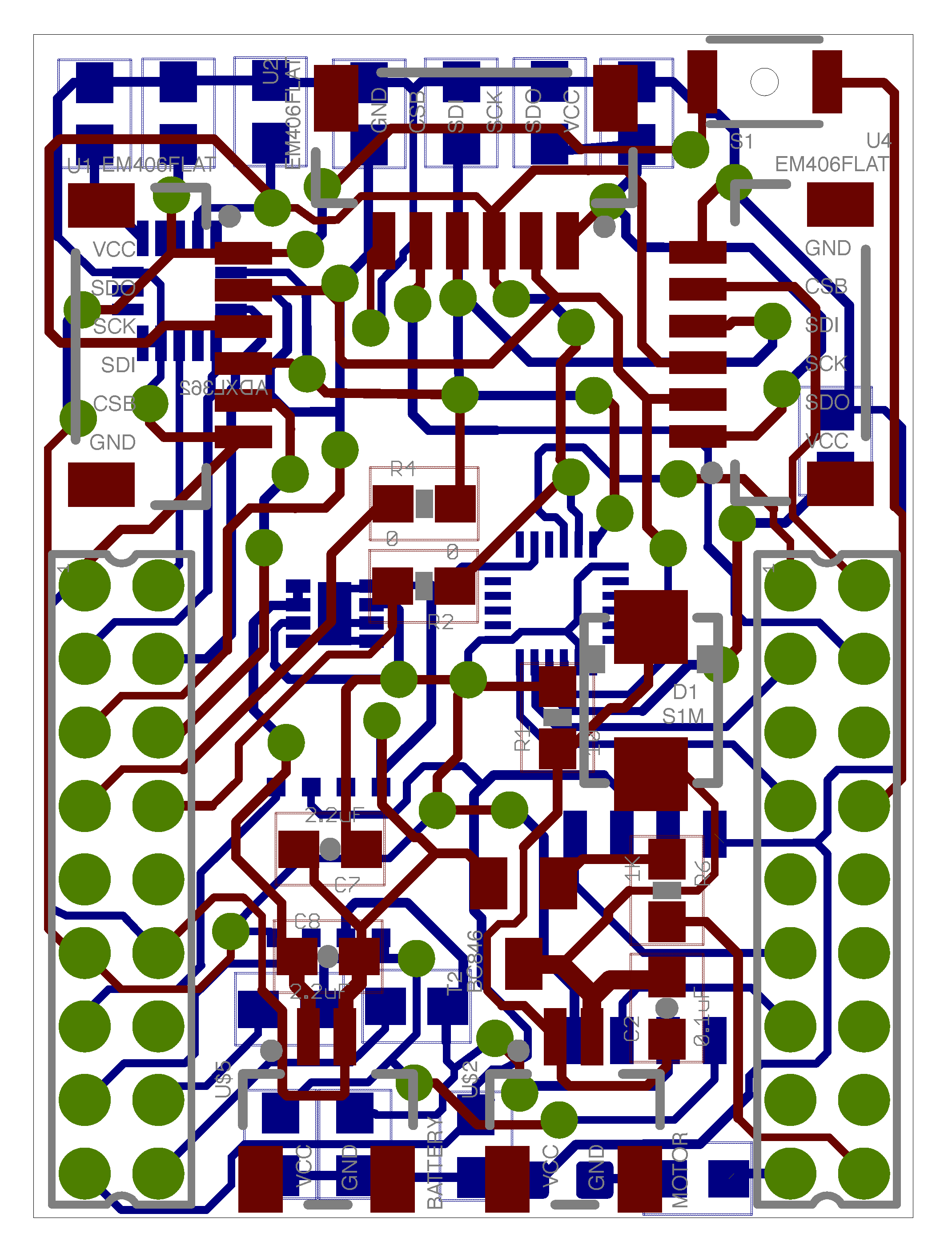
Board design
05/05/2015 at 20:21 • 0 commentsFinally we routed the board. This is the first time we designed a PCB so please forgive any blunders. Managed to squeeze all 3 SPI sockets for potential extensions like pressure sensors. We can already think of some crazy applications.
We also have sockets for battery and buzzer connections. This way there is no need to solder anything, just plug&play.
![]()
Eagle files can be found here.
Now it is "just" off to the manufacturers to order the board and component suppliers to source the parts and we are ready for soldering. Hope all is properly designed :-)
Phase 4 - DONE.
-
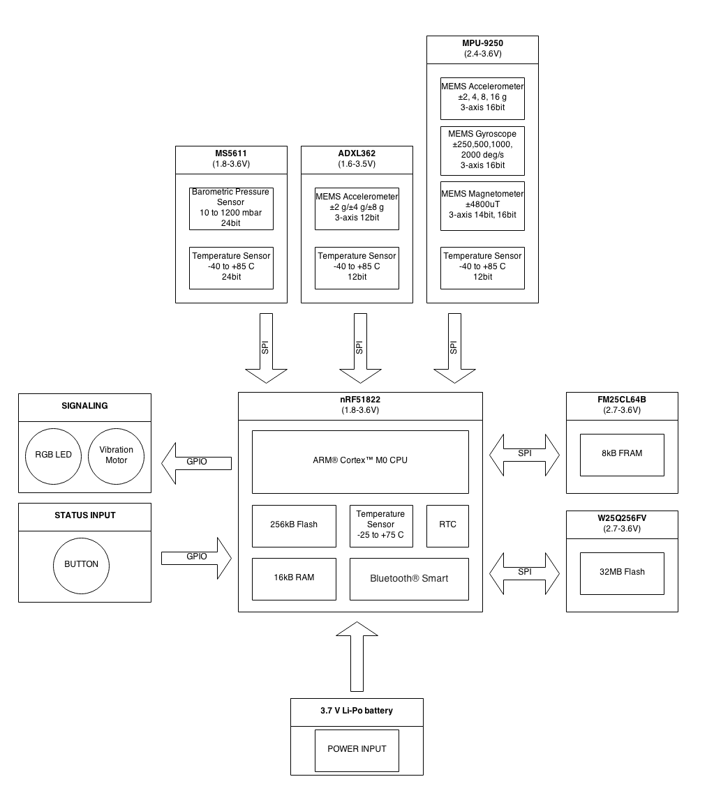
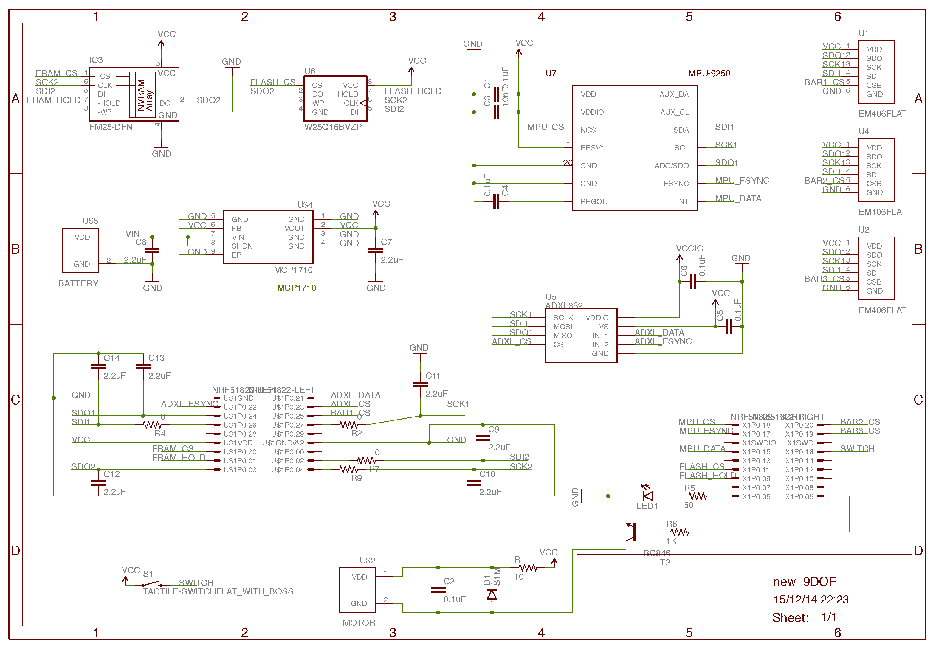
Electrical schematics
04/28/2015 at 20:08 • 0 commentsSo ... the wheels are turning. We have done the electrical schematics for the board. All measurement components (accelerometer, 9DOF and expansion slots) have been put on SPI1 lane, whereas both FLASH and FRAM memories have been separated onto SPI2. Let's hope we can find room to fit three SPI1 expansion slots for additional sensors.
![]() Eagle files can be accessed here
Eagle files can be accessed herePhase 3 - DONE. Now for the tricky part ... squeeze all components on this tiny board. PCB design here we go!
-
Component selection
04/23/2015 at 13:18 • 0 commentsBased on the criteria specified previously we chose:
- Microchip MCP1710 3.0V current LDO regulator
- Analog Devices ADXL362 ultralow power 3-axis accelerometer
- Invensense MPU-9250 9-axis motion tracking multi-chip module
- Winbond W25Q256FV 3V 256M-bit SPI Flash memory
- Cypress Perform FM25CL64B 64k-bit SPI Fram memory
- additionally we plan to use MS5611, MS5803 and BMP280 pressure sensors
Smaller parts include:
- 0603 smd components for optimal size vs. soldering difficulty
- 2.0 pitch 2x9 connector sockets for NRF51822 connection
- 6 pin smd socket for external SPI expansion (ex. pressure sensors)
- 21x32mm LiPo battery of around 120mAh
- Tactile smt switch
- cheap Vibration motor 3-4.5V 0.06A
![]()
BLE Intertial Measurement Unit
Open Source bluetooth enabled IMU with SPI expansion slots. Track any motion


 Eagle files can be accessed