 Mike Rigsby
Let's start with a schematic of the power supply.
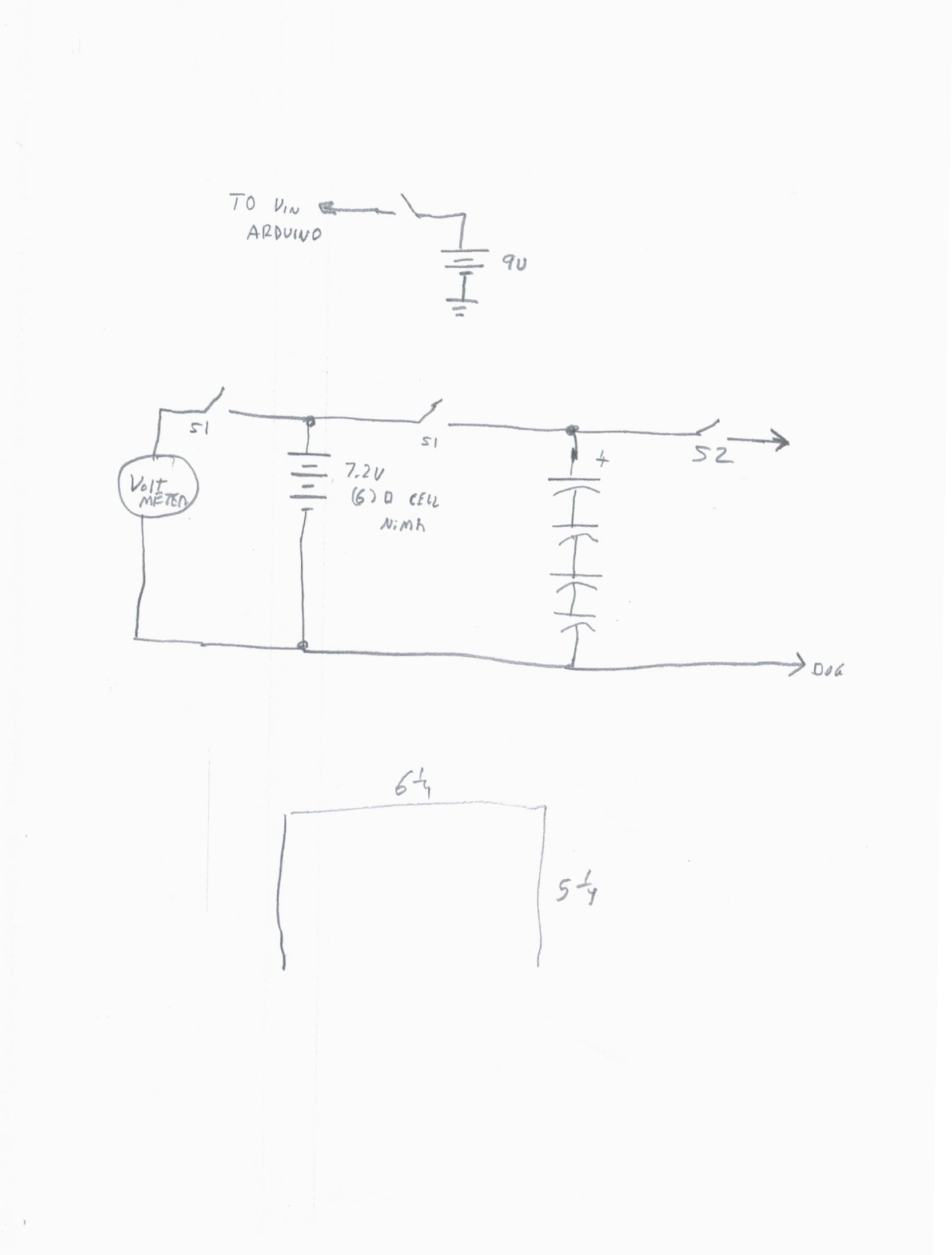
This supply is built on a piece of 5 1/4" x 6 1/4" plywood (1/4" thick). The four 350 farad capacitors are soldered together in series, then placed in the 3d printed capacitor holder.
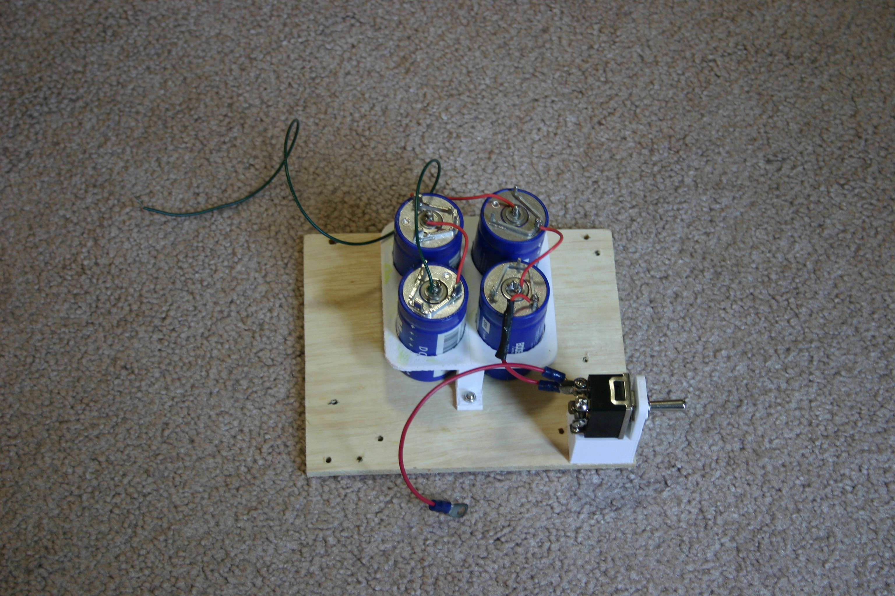
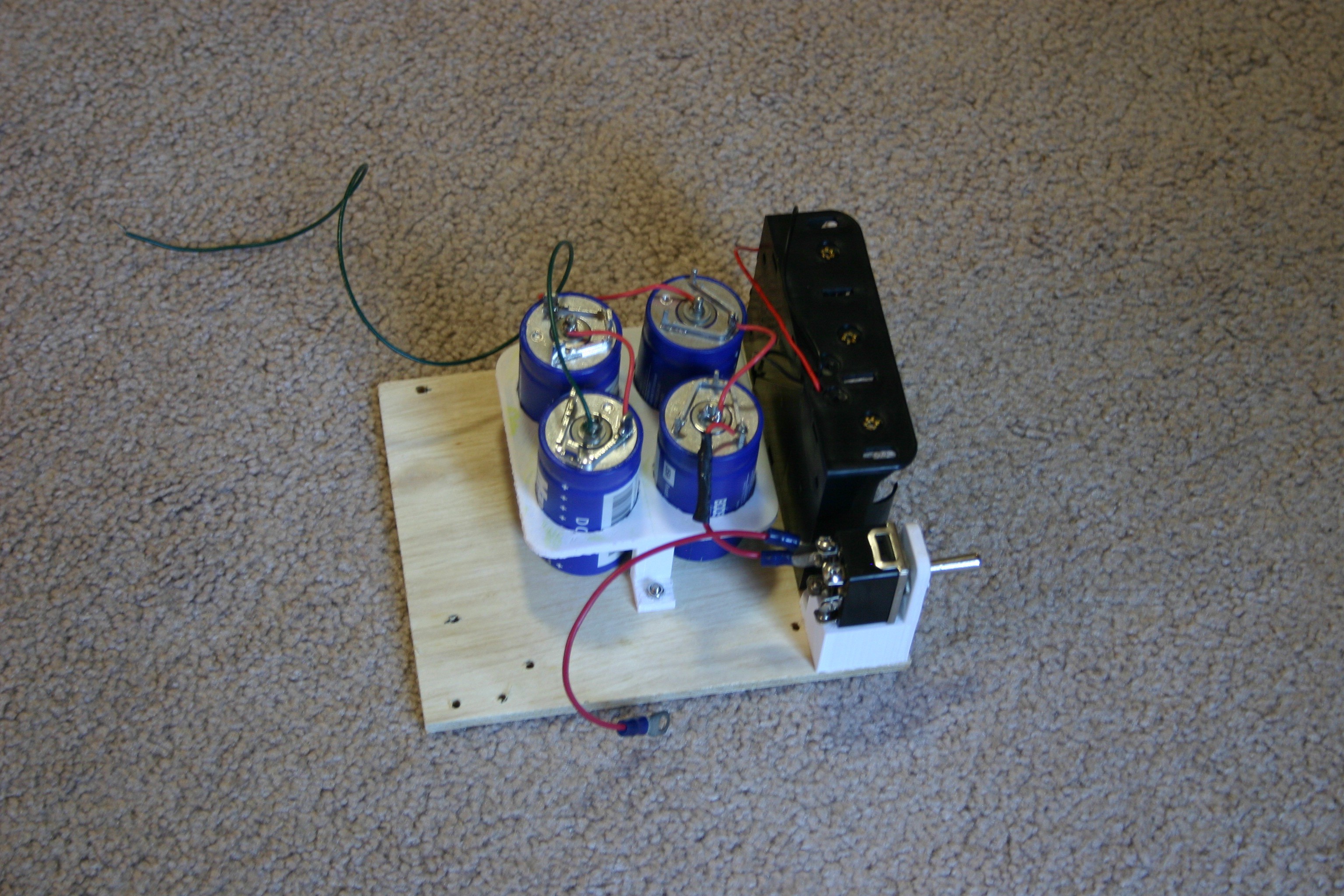
A "three cell" D battery holder is added.
The second toggle switch and digital voltmeter are added.
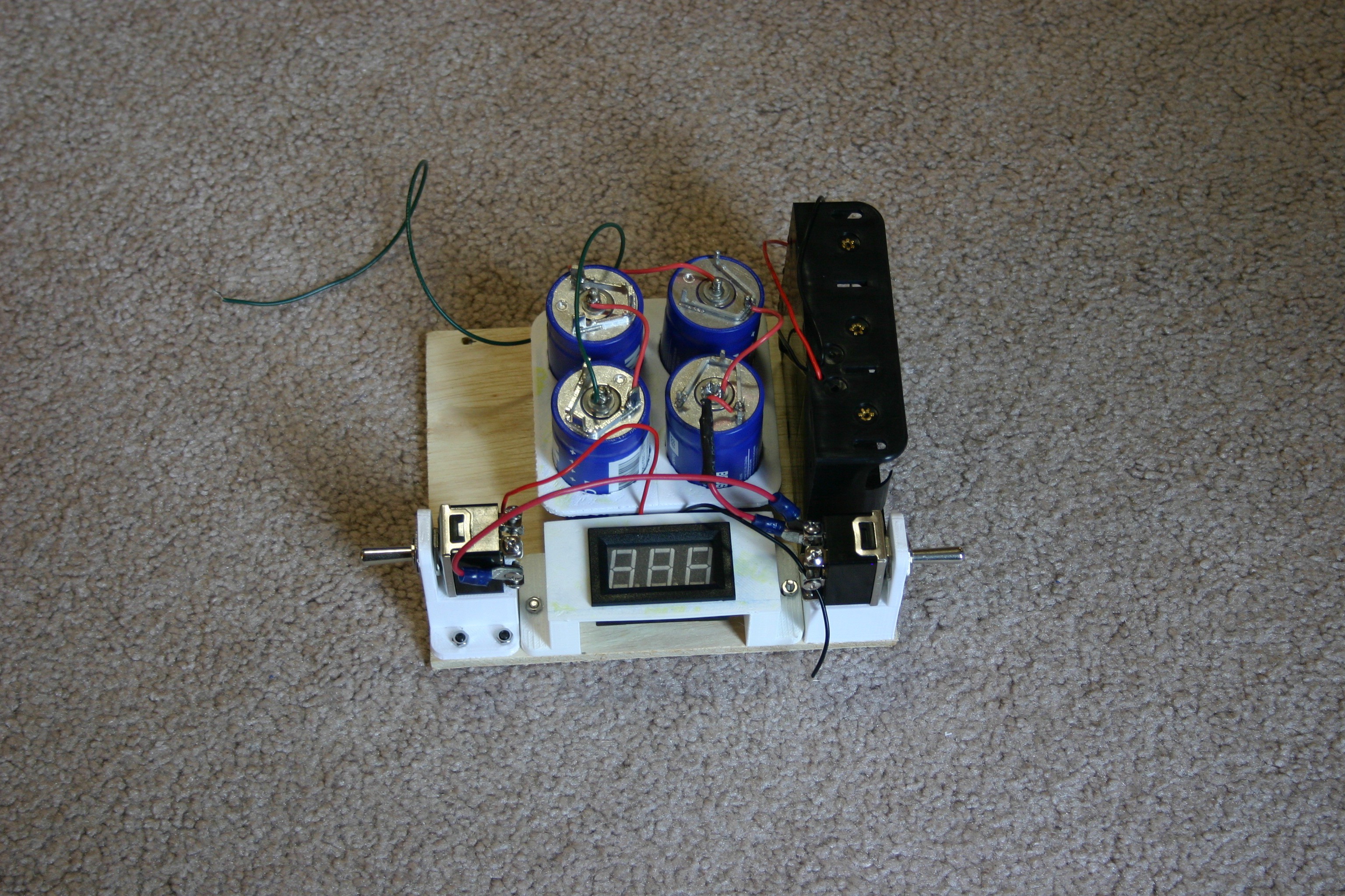
The second "3 D cell battery holder" is added.
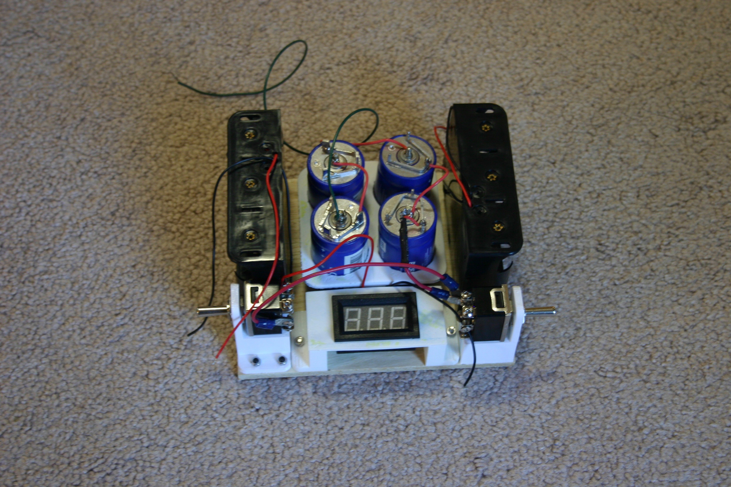
Everything is connected and wired out to a plug that can attach to the dog's body.
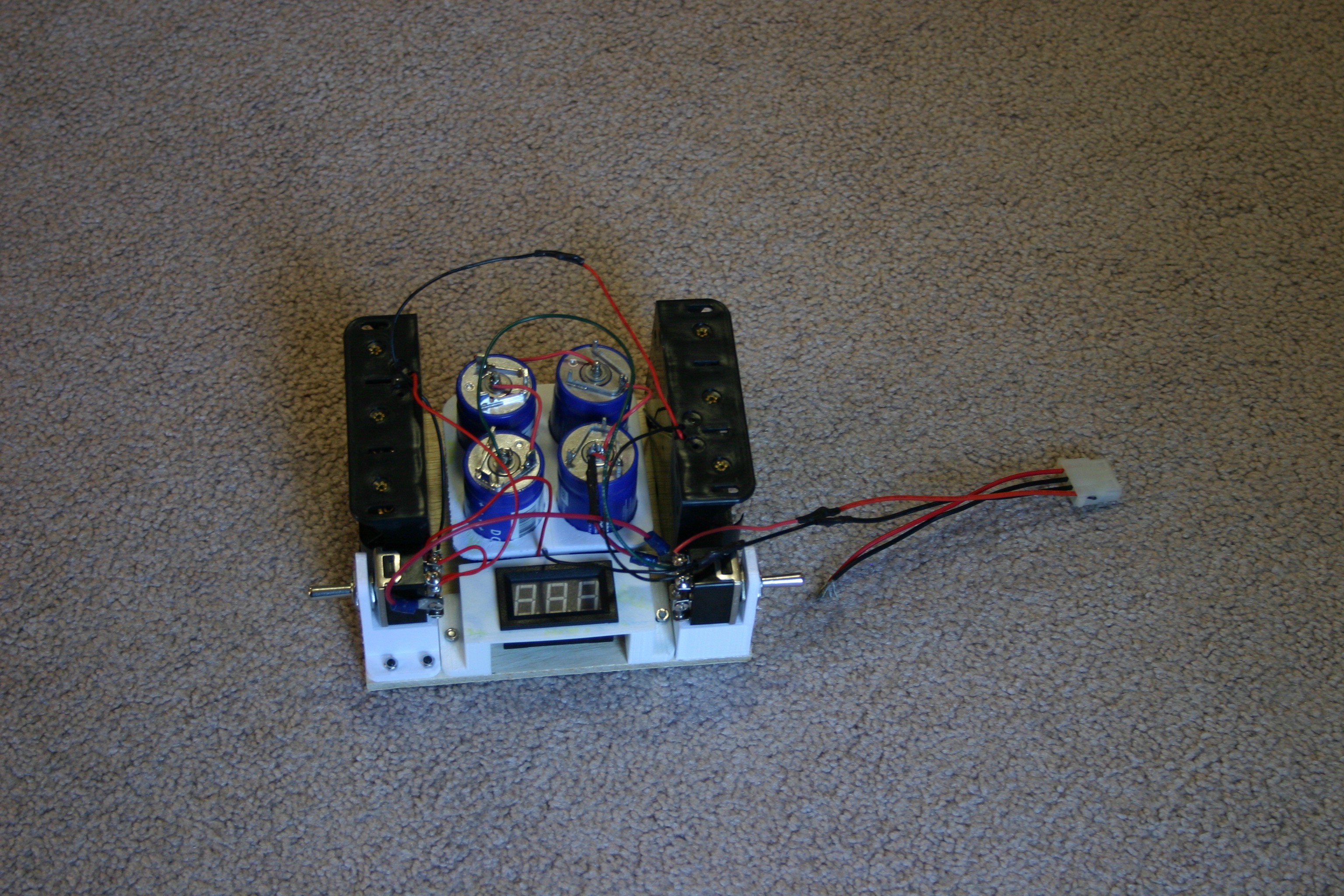
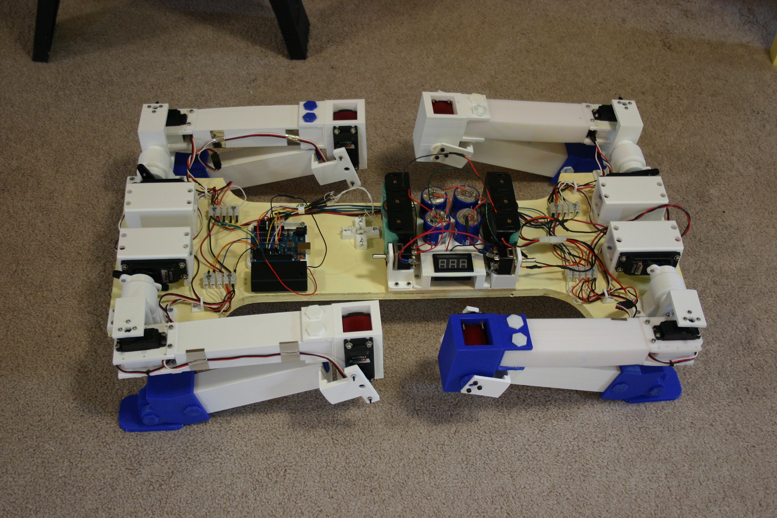
The 9 volt battery holder (with built in switch) and the battery/capacitor power supply are attached to the body using velcro.
Because the dog was tired of being inside, I took her out for a little air.
Discussions
Become a Hackaday.io Member
Create an account to leave a comment. Already have an account? Log In.
Actually, the ultracapacitors tend to have a low maximum voltage (2.7 volts in my case), so they need to be in series to handle the battery voltage.
Are you sure? yes | no
Why are the capacitors in series? Shouldn't they be connected in parallel?
Are you sure? yes | no