-
Apple II BMP Display Success!
09/10/2018 at 06:40 • 1 commentSo, an admission. It’s been a bit since my last update. Turns out that I don't work on this project full-time :)
Anyone that works on hobby projects knows that time is usually the constraining factor when it comes to getting stuff done. Work, fixing things, cleaning the shop, and so on generally gets in the way of meaningful progress on SUPAR AWESOME PROJECTS. That's a big part of why I gave myself a decade to get this project done. Oh, I didn't mention that? Yeah, this is a decade-long project. I think I'm on track.Believe it or not though, I have made some great progress since the previous update. Among other things, I have the full Simplified Perturbations Models running on the INMOS transputer hardware. Last we checked in, I had some stuff running including decoding the TLEs (Two Line Elements) but I had yet to show off actual orbital predictions. But after some epic hacking sessions, that stuff is for real working. I'm going to write those accomplishments up but for now what I want to talk about is this map stuff.
Two posts ago, I detailed some plans to get a satellite map running on Apple II hardware. The first part of this was succeeding in the display of DHGR (Double Hires GRaphics) bitmaps. As in BMP, the stuff that you can output directly from a modern version of Adobe Photoshop here in Twenty Eighteen. That would provide the background map atop which I could display the satellite position. This was harder than I thought it'd be.
The first barrier to getting DHGR running on the Apple II was the lack of awesome documentation. I mean, it was out there but for a guy like me used to including some standard libraries and pushing stuff to a display it wasn't exactly intuitive. I will right now say that it took me a LOT of revisions to get it right. I looked at a lot of on-screen garbage trying to puzzle out what was going on.
![]()
So close.
So, if you'll excuse a little diversion I want to talk about Apple II graphics.
First, the fact that we can display a 560x192 monochrome bitmap on the Apple II is kind of amazing.
Woz, that is to say, Steve Wozniak, was a brilliant hardware designer. He was working at Hewlett Packard when he started coming up with the schematics for what would become the Apple I, and he was all about efficiency in design. Woz was absolutely great at making the very most of the fewest ICs possible. It's fair to say that it would be hard to strip much out of the Apple II and get meaningful NTSC video out of a design. The entire video system is based around the NTSC (and later, PAL) waveforms. Woz basically looked at the required video signal and said, "How can I design a system with minimal cost and display meaningful graphics from a video buffer". To be sure, his business partner Steve Jobs was probably totally on-board with this cost-optimization in the pursuit of producing an affordable computer with maximum sustainability for Apple.
That said, the side effect of reducing hardware complexity was to increase the software complexity. There was no sprite hardware, and the video modes played epic tricks with the timing of the video signal to produce colors. As a result of this spartan hardware design, the higher resolution video modes became fairly complex when it came to memory maps. In modern frame buffers, there is a nice linear correspondence between the byte stored in memory and its position on the screen. On the Apple II, one finds themself hopping all over the memory map to load an image that will be properly displayed on the screen. Line 2 starts at a position farther than it should from Line 1, as does each subsequent line, except the screen hops back 1/3 of the way down (and 2/3 of the way down) to basically interlace these lines in memory.
Oh, and did I mention that alternate bytes are stored in different memory banks?
This makes constructing a DHGR frame buffer a bit of a challenge in 6502 assembly.
![]()
What kind of memory map is this? Oh right, one that makes hardware simpler and cheaper.
On top of that, pixels are stored 7 bits at a time (the 8th bit serves as a funny delay bit in color mode, essentially ignored in mono DHGR graphics), while normal image files are stored 8 bits at a time.
This resulted in what I like to call "the pixel pokey" where I use the carry bit to bang bits back and forth between the BMP and graphics memory.
![]()
Fast forward a bit, and I have a for-real BMP loader running on the Apple II. This is not the first. Sometime after I started, someone beat me to it. That person was Mario Patino, aka cybernesto. You can see his VBMP code here. Unfortunately, I didn't discover his code until after I had my code working, but I did benefit by looking at his sources. My first functional code ran in about 4.5 seconds to display an image, while his ran in about 3 seconds. Some of this is probably attributable to the efforts of Arnaud Cocquière, a demo coder whose work cybernesto expanded on. Nevertheless after examining the code I found a couple optimizations and now mine runs just as fast, even though we do some things very differently. As a side note, I was incredibly satisfied to see that a badass French demo coder was using the same "pixel pokey" strategy as I came up with on my very own, especially considering this was my first foray into a real 6502 assembly project.
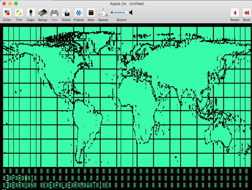
![]()
Beautiful 560x192 monochrome DHGR. TAY never looked so good. That’s a 6502 assembly joke. Nevermind.
At the end of the day, I can fill the screen with just about any 560x192 monochrome bitmap I want. This is pretty cool. Next up, I get to figure out how to show the satellite location with a sprite, and plot a curve showing the next orbit. This will be pretty interesting, as it will require either double-buffering or some crazy caching of the background to make it work.
As a side note, I believe I have a pretty awesome dev environment for Apple II stuff. I definitely owe thanks to John Newcombe who showed the way to using VSCode with Merlin32 and Gerard Putter's most excellent Virtual ][ emulator. If you check the keplermatik-map GitHub, you will essentially have a skeleton project that allows you to build and run Apple II 6502 assembly with a simple "Command-B". This is vastly faster than my previous method using Virtual ][ and AppleScript with native Merlin-8 for development and I get the bonus of a modern IDE with nice 6502 syntax highlighting courtesy of the BEEB VSC plugin.
-
How to Speak Transputer
08/07/2016 at 02:27 • 4 commentsHello Hackaday.com readers! Not sure who submitted my project (if anyone) but I am excited to see it there nonetheless!
When I last checked in, I was working on a solution for the graphical display of satellite position. I'd decided on the Bulgarian Pravetz Apple II clone as a suitable platform, and had been working away on some 6502 assembly code to draw the map and satellite position. I also said, "something-something hook Bulgarian Apple II clone up to transputers" and proceeded to ramble on about other stuff.
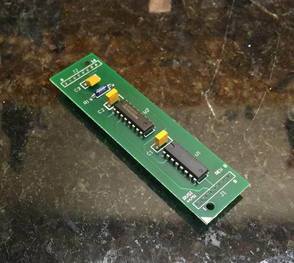
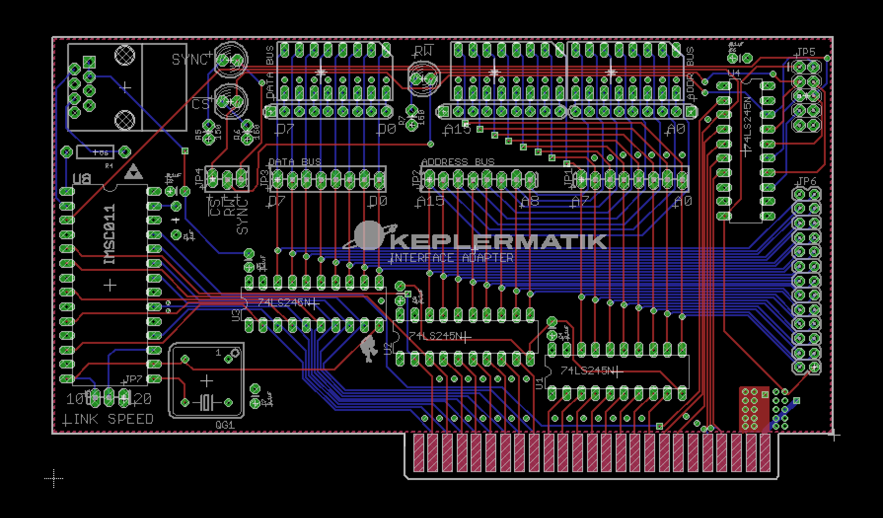
At some point I did mention that a design for the link adapter interface would be forthcoming. Let it not be said that I don't deliver. I give you, the Keplermatik Interface Adapter:
![]()
Yep. It's a circuit.
First of all, the more astute observers among you will notice that there's a bit more going on with this board than a simple link interface. There are a few buffer chips, some LED arrays... Oh wait, it's...
BLINKENLIGHTS!As I was drawing up this circuit, I started thinking about how handy it'd be to break out the bus signals for debugging purposes. That led to thinking about how old machines showed all that on the front panel, and at that point it pretty much came a foregone conclusion that Keplermatik was getting some sweet address and data bus activity indicators, a.k.a. Blinkenlights. For early development, there are some onboard LEDs that will provide a sweet disco scene under the hood, but more importantly there are some double-row headers toward the rear of the card that will connect via ribbon cable to a DB25 and DB9 on the back side of the machine. Later, the Keplermatik console will have some nice big blinkenlights that connect to those ports.
So enough about lights, what about the super-awesome INMOS transputer link?
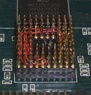
![]()
As mentioned in an earlier post, this board is designed around an IMSC011 link adapter, pictured above. This is the chip that does the important work of allowing the Apple II to talk to those wily transputers.
When in its Bus Interface mode, it's silly how easy the IMSC011 is to interface to the Apple II. The 6502 uses Memory Mapped I/O, and the Apple II has some special address decoding going on that allows a peripheral slot to know when it's being talked to.
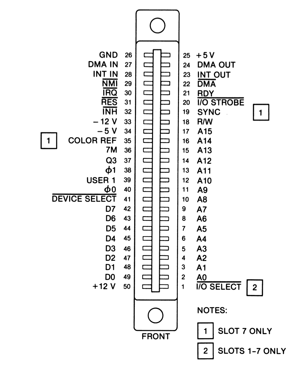
![]()
As seen in the above connector pinout diagram, Pin 41 of the bus is called "Device Select", and the decoding circuitry takes it low when any memory in the range $C0x0 to $C0xF is accessed (where x is the slot number + 8). This can conveniently be connected to the IMSC011's Chip Select (CS) line, which enables the link adapter when taken low. This signal, combined with the RW (read/write) line and two address lines, is basically all that's needed outside of the data bus to send and receive data through the link adapter.
About those two address lines. The IMSC011 has a set of registers that can be read and written to determine link status. These registers are selected through various combinations of the RS0 and RS1 Register Select lines, and connecting these to the lowest bits of the Apple II address bus essentially maps those registers into the Apple II's address space. How, you ask?
Remember how that device select line goes low when memory in a certain range is accessed? That's because the address decoding circuitry ignores the 4 lowest bits of the address, leaving them available for the device to do stuff with. So, if we connect the 2 lowest bits of the address bus (represented by the A0 and A1 address lines) to the IMSC011, then when the Apple II bus selects those lines in the process of accessing its memory the registers will appear on the data bus.
Another side effect is that since we're ignoring A3 and A4 (and the Apple II isn't decoding them to select our device), then the registers actually repeat throughout that portion of the memory space! For example, the register at $C0x0 will also appear at $C0x4, $C0x8, and $C0xC.
One thing about hardware of this vintage, there are no fancy SPI peripheral drivers or anything like that required to interface with it. All you need is to read and write some memory addresses from assembly, BASIC, or whatever. An elegant method, for a more civilized age.
So what else?
Aside from the circuitry just described, there is a 5MHz oscillator to drive the IMSC011, a jumper to select the link speed (10 or 20 Mbps), some miscellaneous caps, and an RJ-45 port for the INMOS link itself.
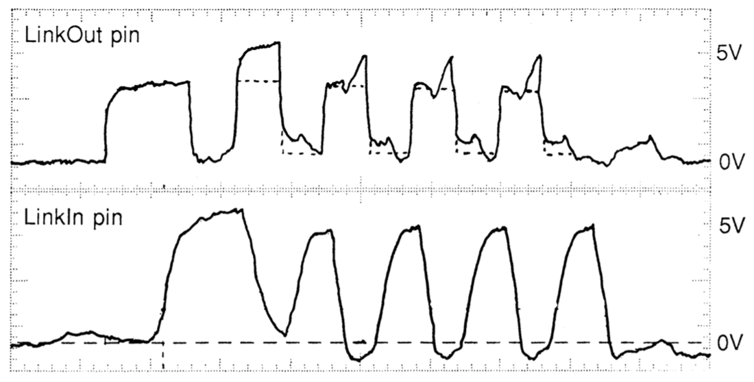
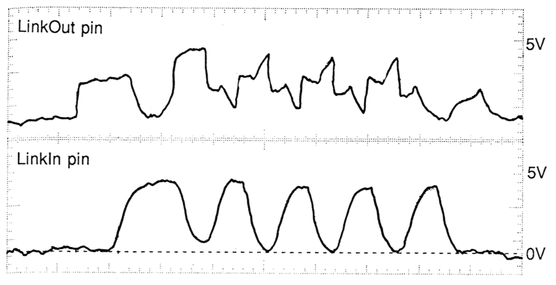
Oh, there is in interesting little detail that I dug up in an INMOS technical note about series termination of the INMOS link. Adding a 56 ohm termination resistor provides proper impedance matching when using twisted pair. The graphs below show the signal with and without series termination.
Without Series Termination: Ringing and Overshoot. So. Not. Legit.![]()
With Series Termination: Clean as a Whistle!![]()
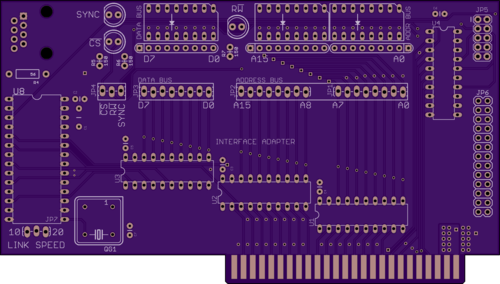
Well, that pretty much wraps up this installment. I'll leave everyone with this nice rendering of the board that OSHPark spit out when I placed my order. Purple will do for now but I'm thinking that when this all goes together for real, a more era-appropriate color is going to be necessary!
![]()
-
Graphics, retrostyle.
07/25/2016 at 00:27 • 0 commentsAs I’ve been developing this satellite tracking console, the goal has been to create a really unique piece of hardware that does useful work. The fact that it’s built up from a very eclectic collection of parts is pretty important to the aesthetic, so when I started thinking about doing a map-based display of satellite location, I had to do some hard thinking on what to use.
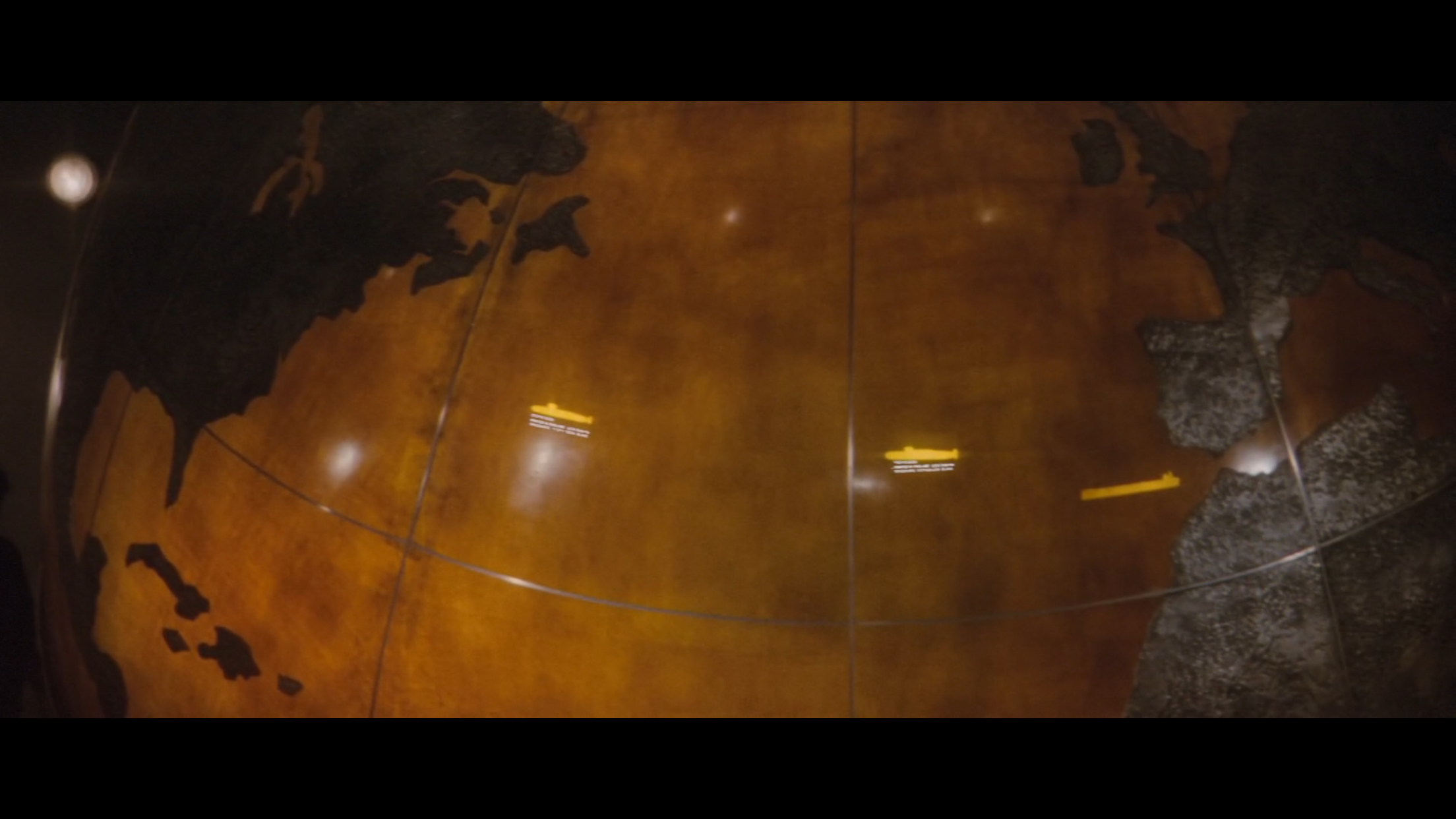
When it comes to Cold War-era display hardware, I first considered going purely electromechanical. This type of map can be seen in the James Bond movie, “The Spy Who Loved Me”. In the climactic scene, there’s a huge semi-transparent globe with lights underneath that designate the locations of the hijacked submarines and the nukes they launch. Major retrocool aesthetic to be had there, no doubt.
![The evil Stromberg didn't deserve a map this legit.]()
Stromberg did not deserve such a legit map.
Looking at how I could accomplish this, I considered using a piece of plexiglass that I would mask off and etch latitude and longitude squares into. This panel would cover a simple X-Y robot that could position a glowing LED anywhere underneath that panel, which could fade on and off in a convincing fashion to show the location of the selected satellite.
While the effect would undoubtedly be fun to watch, the electromechanical technique had a major shortcoming. There was no way to easily show the curved line showing the future track of the satellite. This feature is one of the coolest things about satellite tracking maps, and I didn't really want to give it up. I considered trying to build the ability to form bezier curves out of a light pipe into the X-Y bot, but that was starting to get pretty complicated. I also thought about using a galvanometer and laser to trace the curve onto the panel at high speed, but I wasn’t sure about dumping that 80s aesthetic right on top of my 60s-style map.
Since it was starting to become obvious that the display would most likely be purely electronic in nature, I started thinking about CRT-based displays. One of the first things that came to mind was to hack a vector board from an old Atari arcade game (like say, Asteroids) into the system and use that with some DACs hooked into the transputer hardware. There’s a lot that I totally loved about that idea, especially considering how much I adore those old Atari vector games, but there was another factor that played into my eventual decision: my long-standing desire to create something useful with 6502 assembly.
![]()
The MOS Technologies 6502 is one of the most ubiquitous microprocessors of the 20th Century, and can be found everywhere from embedded systems to the original Nintendo Entertainment System. In fact, 6502-based hardware was responsible for some of the coolest consumer electronics of the Cold War era. Here’s a short, not all-inclusive list of 6502 love (including variants such as the 6507 and 6510):
- The aforementioned Nintendo Entertainment System.
- Commodore 64, best selling computer of all time.
- Commodore VIC-20, predecessor to the 64.
- Commodore PET, predecessor to the VIC-20.
- Commodore 1541 Floppy Drive. Commodore really loved the 6502!
- Atari 2600.
- Atari 800.
- Tamagotchi. 6502 in your pocket!
- BBC Micro. Even the Brits loved the 6502.
- Bender Bending Rodriguez, bending robot. Shown to have a 6502 in his noggin in the Futurama episode, “Fry and the Slurm Factory” :)
- and last, but certainly not least, the Apple I and II. That’s right, the chip responsible for computing whether your beloved Mario fell into the abyss is the same one responsible for informing you of your death from dysentery.
When it came to choosing a 6502-based platform to assimilate as part of this beast of a project, it was kind of hard to find one that fit the ‘theme’ of exotic, industrial-grade hardware. That list above? Full of gaming systems and kiddie stuff. None of them too rare, either.
The whole 6502 idea might have actually stopped there, were it not for the fact that Ivan much preferred industrial espionage to actual engineering. There was hardly a single piece of commodity silicon that the Soviets didn’t rip off, and when it came to building computers around them they could hardly be bothered to design those completely from scratch, either. And that’s how the Pravetz 8-bit computers came to be.
![WTF Commies. In ur fabs, ganking ur masks.]()
Those crazy Soviets: in ur fabs, ganking ur masks.
These rare (in Western terms), Bulgarian masterpieces of ‘engineering’ are compatible with (read: copies of) the Apple II, and that makes them both exotic enough to qualify for a place in this project and straightforward enough to implement an awesome map display upon. The difficulty level of this whole project is already through the roof, and to be honest I was looking forward to getting down with one of the most well-documented platforms on the planet. Even better, there are all sorts of Apple II emulators out there that I can use for development, which lets me both develop while traveling (one of my favorite ways to pass time while waiting to get to the next place) and also severely reduces my assemble/reboot/run cycle time.
Having chosen a platform, it’s been pretty fun to develop the map display from there. My general roadmap for this subsystem is as follows:
- Investigate Apple II display modes and determine the most suitable.
- Choose a 6502 assembler.
- Create a compatible background map in bitmap format.
- Write assembly code to display said map.
- Create an Apple II expansion card that can talk to the transputer subsystem.
- Write expansion card driver code to receive satellite position and metadata.
- Write assembly code to blit a sprite representing satellite location.
- Combine map bitmap, transputer interface driver, map display code, and satellite position display code into a single ROM image.
- Burn ROM image to EPROM.
- Hope it all works!
I’m currently in the middle of items 4 and 5. For display mode, it’s double hires all the way, especially considering I prefer a monochrome display. Unfortunately, this is also the most difficult display mode to implement in assembly, given how it interleaves the pixels between completely disparate parts of the Apple II memory map. The common way to deal with images on the Apple II and many other 8-bit-era platforms is that the BSAVE routine ‘pre-interleaves’ this data, letting one simply BLOAD the image, presumably because speed in most situations is more important at time of loading than saving. However, considering that I’m only loading the image once in the beginning, I’d rather sacrifice speed for compatibility and use a standard .BMP file.
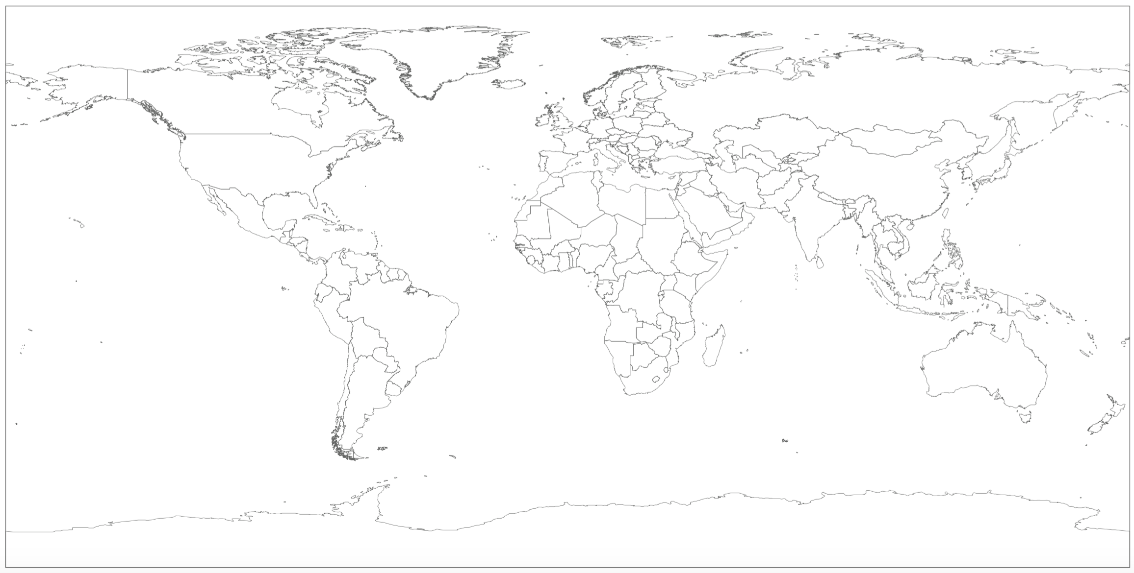
About that background map. You wouldn’t believe what a nightmare it is to get Photoshop to output a non-anti-aliased, black-and-white bitmap, given a vector input image! That whole workflow was a complete pain in my ass. First I had to find a fairly clean vector image showing continent outlines. That was harder than one might think! Then I had to do some tedious cleanup on that image, getting rid of text and some boundary lines that I didn’t really care about (the individual country borders, for example). Once I had clean vectors, I had to work out how to rasterize and scale that image, complicated by the fact that double hires mode uses rectangular pixels as opposed to square. Then I overlaid an accurate latitude and longitude grid. Finally, finding the magic options to Photoshop’s BMP format that got me a clean 1-bit image without aliasing got me something I can work with.
All in all, it took several hours to turn this:
![]()
Into this:
![]()
Where choice of assembler is concerned, I decided upon Merlin (specifically Merlin Pro, which supported ProDOS). Merlin actually survived into the IIGS era, and is highly capable. I’ve also had great luck scripting it with my Apple II emulator of choice, Virtual ][ (shout out to Gerard Putter, who provides excellent technical support!). With one key combination, I can essentially assemble, save the object file to disk, save the source code to disk, reboot, and run my code. With another key combination, I reboot into Merlin and reload the source code. What our friends developing Apple II software in the 80s wouldn’t have given for that! As an added bonus, I have a full debugger in Virtual ][ that lets me set breakpoints, inspect registers, watch memory locations, et cetera. Legit.
Progress in writing the code to load and display the map on-screen proceeds. I had a little misunderstanding when it came to how the pixels get interleaved between Main and Aux memory, resulting in a bunch of work getting trashed, but back on track after finding some clearer documentation. I would probably be done by now, but I am doing some things in a more generalized manner than strictly necessary, in case I want to reuse any of this code later.
![]()
No, TAY doesn't stand for Taylor Swift. I'd be ok if it did, though.
Essentially, I’m writing a generic loader for regular BMP files of double hires resolution. This is something that I haven’t really come across before as again, most of the image loaders deal with files that had the necessary memory interleaving happen at the time of saving. Also, double hires graphics just wasn’t that popular to begin with. For example, BSAVE/BLOAD for double hires graphics is not nearly as standardized as it is for regular hires graphics, with some formats using a single file and others using two.
When it comes to design of the transputer hardware interface, I’ve made progress but less than I have on the software front. It’s interesting, because transputers themselves communicate with the outside world (and perhaps more significantly, each other) using serial links running at speeds from 5 to 20 Mbps. These links are a nice piece of engineering on the part of INMOS, but there’s not much else out there that uses the standard. However, while the links are actually part of the transputer silicon, INMOS also made a couple link adapter chips to interface with other circuits.
![]() Imagine that, no Eagle parts libraries out there for INMOS Link Adapters. Quickly remedied.
Imagine that, no Eagle parts libraries out there for INMOS Link Adapters. Quickly remedied.The link adapter chip I’m working with is the IMSC011. It has two operating modes, one a simple parallel interface with a two-wire handshake, and another intended for use with microprocessor buses that map peripherals to memory. While the first mode will come into play when designing circuitry to control the project’s Panaplex and VFD displays, it’s the second that will be used to interface with the Apple II’s bus. I’m currently working on drawing up this circuit in Eagle, my preferred PCB and schematic design software. It’s a lot of fun, and the address line decoding stuff will be a good refresher for when it comes time to build the 8088-based SBC for the Soviet side of the project that calculates doppler shifts and points the antennas.
So there’s where I’m at with the project, namely the graphic display of the satellite’s position. I’ve been working on several other fronts, having re-started the port of the SGP models from clean C++ code among other things, so I have a lot more updates to write. One thing in particular that I want to write up is how I configured Eclipse on Mac to write, compile, and run code using the INMOS DOS tools and WINE. I figure others might benefit, but I also need to document it for my own good in case I ever want to set it up again! So look for that update and more in the near future, I’ll try not to take so long between updates next time :)
-
TRAMs, Green Wires, and Fake B008s
05/25/2015 at 20:01 • 2 commentsTime for another project update.
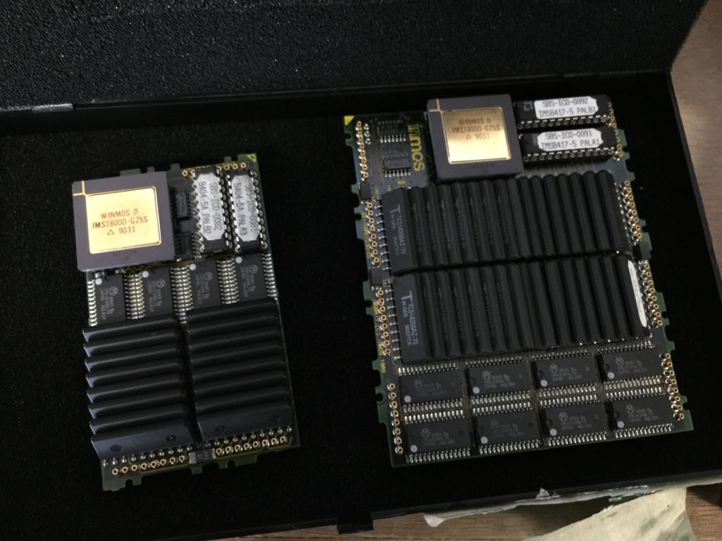
At the time of my previous report, my next steps were to get the orbital models running on real transputer hardware. Not the simplest task, considering the technological archeology required, but a fun one. So without further adieu, I present the transputer modules (TRAMs) in question:
![]()
TRAMS.
The one on the left rocks 2MB of DRAM and the one on the right 4MB. Kinda nice to have a real memory controller in these things. You can even run a real OS on one (or more). That's a story for another day, though.
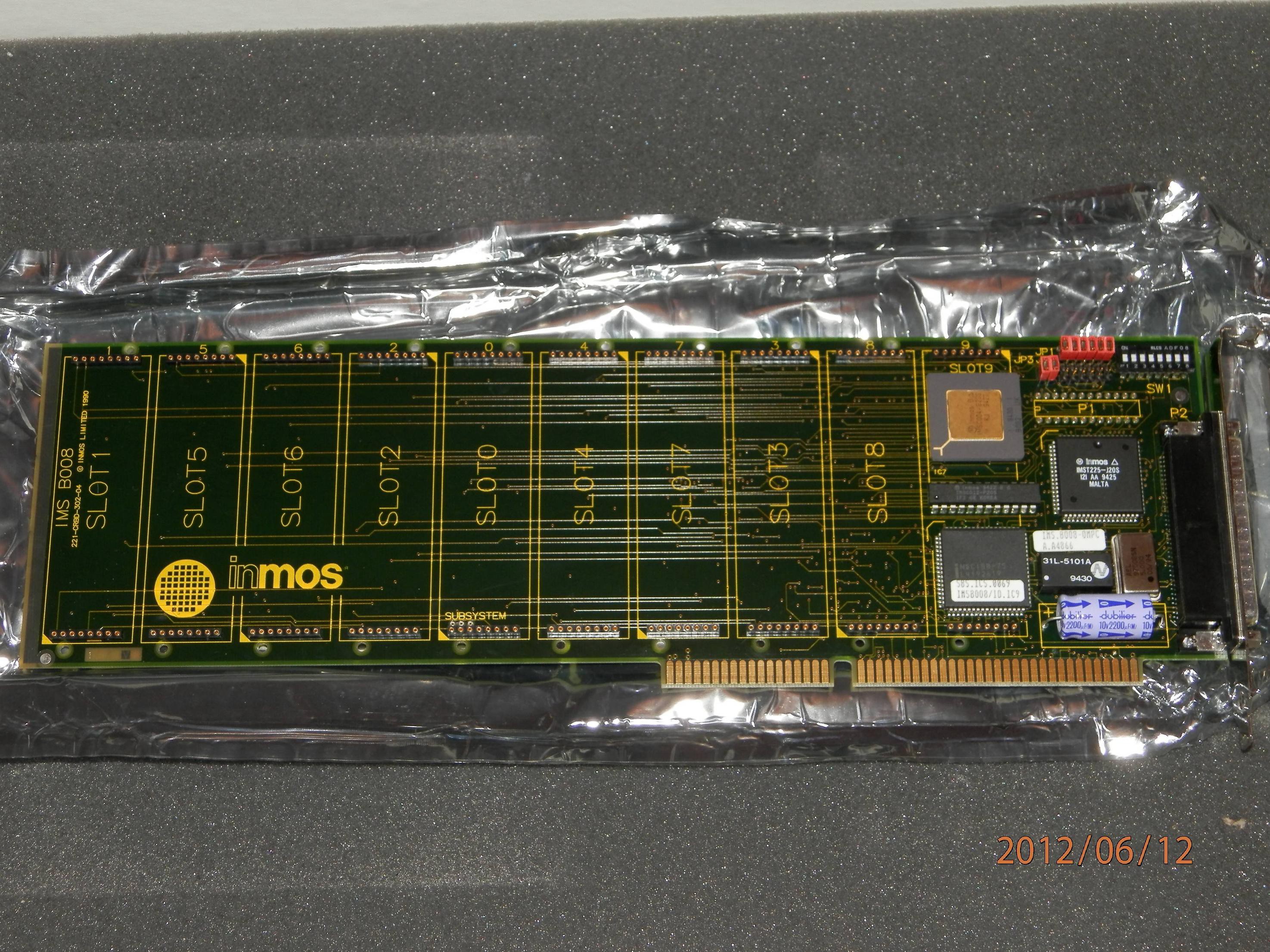
The next question becomes, how to load code onto these odd beasts? Today, in the world of Arduino and countless clones, everything is USB- and flash-based. You plug your board into USB and a fancy bootloader programs your code into flash memory, you reboot the micro and it runs your code. Not so, here. The TRAMs don't have flash (or any other non-volatile storage) and USB certainly didn't exist back then. Instead, the TRAMS usually wound up in an expansion board that plugged into the host computer. INMOS (creator of the transputer) designed and sold boards for IBM PC-compatibles, Sun SparcStations, and so on. One of their most popular boards, the B008, boasted space for 9 TRAMS and a name just begging to be giggled at by immature young men:
![]()
Hur, hur. He said, "B008".
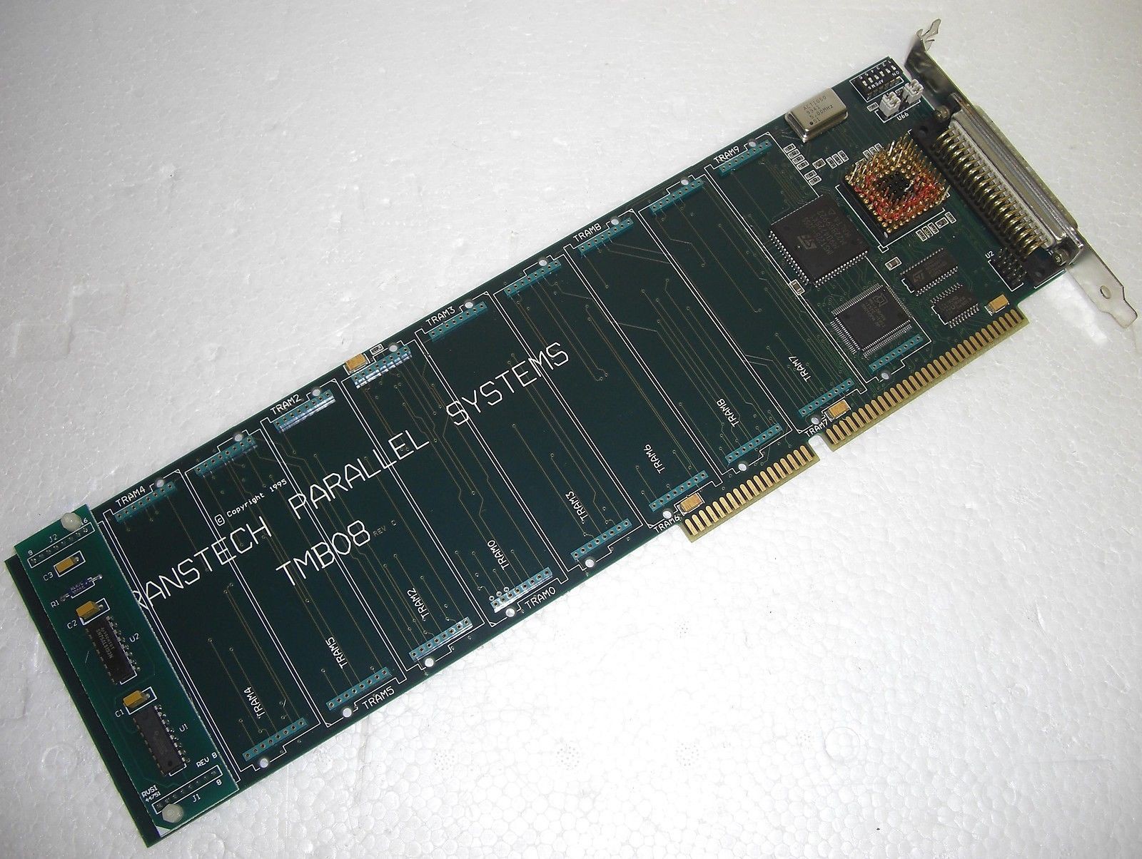
Not my board. Wish it was, but alas they're rare as hen's teeth these days. I found one guy with a board on some random website, and emailed him to see if he'd sell, but he wasn't interested. Instead, I found one of these on eBay:
![]()
What we have here is a sort of weirdo knockoff of the B008 (dare I call it a 'fake B008'?), made by a company called Transtech. They made industrial control hardware (for which transputers are pretty well suited) and advertise their TMB08 to be 100% compatible with the INMOS B008. Fair enough, so Buy It Now, right?
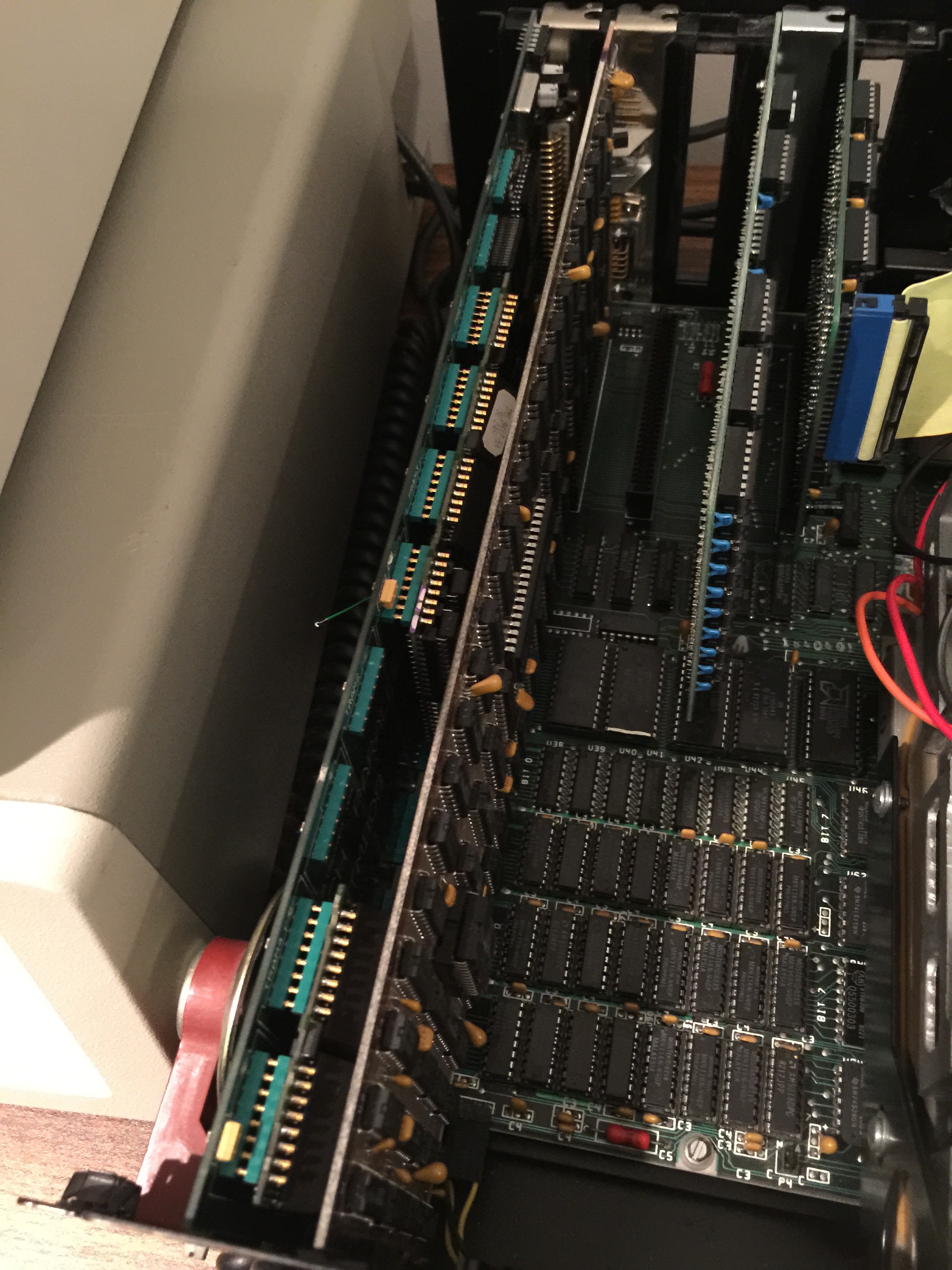
Not so fast. In addition to a much less amusing moniker, I noticed a little bit of oddity in the above picture (which is from the auction). First, there's a little goofy module plugged into the leftmost TRAM slot. We also have a funny looking red porcupine looking thing on the right, that upon closer inspection has a bunch of wire-wrapped connections. And on the back, which I unfortunately didn't get a pic of, the TRAM0 slot was sporting a couple mysterious green wires soldered between its headers. Last but not least, this B008-shaped thing has a card edge connector the likes of which haven't been seen for a loooong time. That there, ladies and gentlemen, slots into the grandaddy of all IBM PC buses: ISA. This architecture debuted in the O.G. IBM PC (model 5150), in 1981. Good thing that I have one of those, so I decided to ignore all of the oddness and give it a shot. TRAMs installed in board, I plopped it into the 5150 and attempted to establish communications. Unsurprisingly, that was a failure.
![]()
That thing on the left: Fake B008 plus two TRAMS, sitting snugly against the CGA board of the 5150. You can see one of the bastard green wires sticking up shortly after I forcibly disconnected it from the top header of the TRAM0 slot.
So I spent approximately a whole evening attempting to ignore the oddity of the weirdo module, porcupine thing, and mysterious green wires. Instead, I went through the pain of trying countless combinations of IO addresses, IRQs, and DMA channels in an attempt to get a response from the board. In retrospect this was silly, though I have to say that IRQ conflicts and such were pretty common back in the day and it wasn't uncommon to spend some frustrating evenings doing battle in the same way.
Finally admitting to myself that I was going to have to dig into whatever logic was behind the strangeness, I set to researching both the B008 and the TMB08. I found schematics and other documentation, and it became apparent that the TMB08 was, as advertised, compatible with the B008 but that mine had been in some way altered.
The porcupine thing turned out to be slotted in where an INMOS C004 32-way crossbar switch normally goes, both on the B008 and the TMB08. To understand its function, it's important to know that each transputer chip has 4 high-speed links that can connect to other transputers or peripherals. Depending on the problem to be solved, multiple transputers can be linked together in different ways, and the C004 provides a configurable way to accomplish this. At the time software is loaded on to the board, a configuration file is also sent to the C004 telling it how to link the TRAMs together. Turns out the purpose of the porcupine thing (referred to in the official docs as a 'hedgehog') is to hard-wire some of the links in a defined fashion without the expense or reconfigurablility of a C004. In particular, it routes some links from the TRAM1 slot out the D-sub connector on the back of the card. For what purpose? For this we have to look at the other modifications.
![]()
Porcupine or hedgehog? Either way, not as cute as the real thing.
So next we have the two green wires, connecting bits of one TRAM0 header to the other. Looking into the documentation, it appears that the wires essentially bridge the PC configuration link out to the TRAM1 slot.
So bastard green wires connect PC to TRAM1 and the hedgehog connects TRAM1 to the outside world via the connector on the back of the card. What then, could be on that module in the TRAM1 slot? I had a suspicion, but needed to confirm.
![]()
Most decidedly not a transputer module.
So those little ICs onboard are an RS-422 receiver and driver, making that module an RS-422 transceiver. At which point it all becomes clear, and my suspicions are confirmed.
RS-422 is a differential signalling protocol that basically allows for communications up to 10Mb/s (the same speed as the INMOS transputer links) up to 1500 meters. Remember when I said that Transtech made industrial controls? If you're in an industrial environment, you have a lot of stuff like motor drivers and sensors hooked up to those transputers. All that stuff wouldn't fit into a PC case with your B008 knockoff, so you put it all (including the transputers themselves) in an external enclosure. Except you now need a way to talk to your INMOS gear from the PC, and RS-422 seems like the perfect signalling method to carry the message.
So what Transtech needed was a card that converted INMOS links to RS-422. They saw a way to modify their standard TMB08 card to bridge the PC link through the RS-422 module out to the rear connector, and voila. They added weirdo module, porcupine thing, and bastard green wires to get the job done. Fast forward many years, random guy buys card on eBay expecting it to be a normal TMB08, except it's not.
So in order for me to get this thing to run like a REAL fake B008, it's necessary to reverse their modifications. Out comes the module, off come the green wires, and the the porcupine socket is dequilled. I don't have a real C004 to go in that socket, but that's ok because I'm only using 2 TRAMs and some of the links are hardwired by default.
I put the card back into the 5150, booted it up, and...
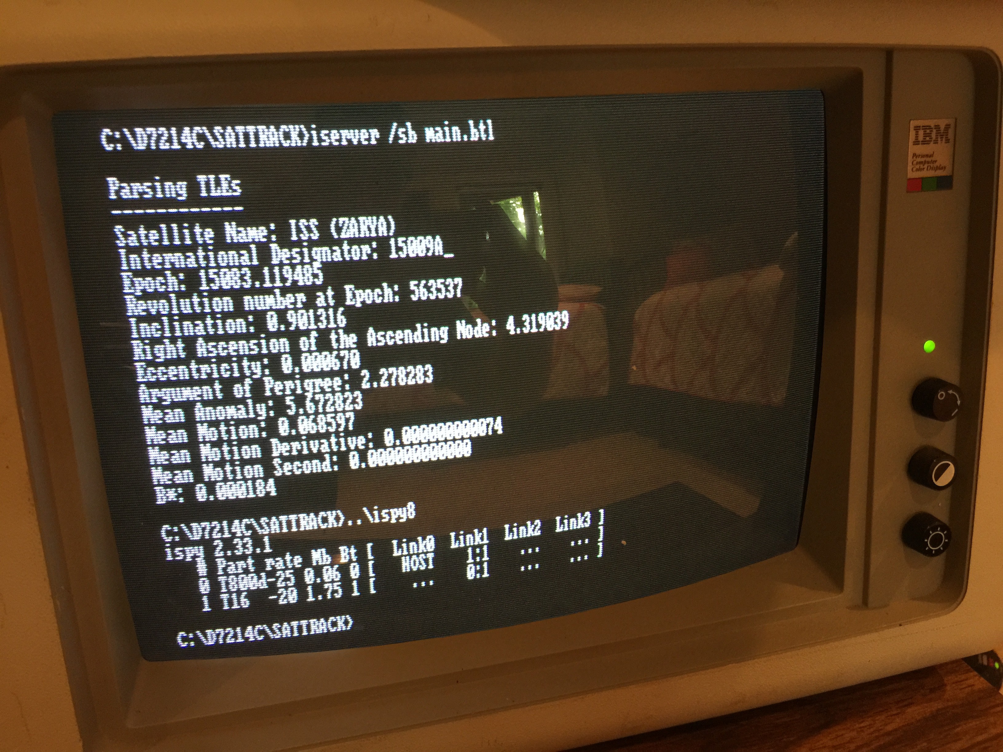
![]()
TRANSPUTING. FOR REAL.
The ispy8 command there shows the TRAMs onboard. At this point I only had one of my TRAMs in the socket, though it's showing two. The other transputer (T16-20) is actually a small one soldered onto the board whose job is boot the other transputers. Confusing, I know. What's really fortunate is that Transtech somehow left that transputer on the board, as it wasn't required for their application as an INMOS link adapter to RS-422 card. Interestingly enough, another TMB08 on eBay looks to have been modified for the same purpose and is actually missing that transputer chip. Guess they got wise after awhile?
Of course, also shown is the output of my code, finally running on a real-deal transputer.
Next time, I will probably detail some of the design for the Panaplex and VFD display boards. Or maybe casting new legends for space buttons. Or maybe researching S100 computers to build the Soviet 8080. So much to do!
-
Adventures in Retro Display Technology
04/21/2015 at 06:45 • 0 commentsSo the console actually has two sides, one built out of vintage 60s/70s/80s American computing and interface technology and another out of Soviet. The American side is going to handle calculating the satellite's relative position to the station, and the Soviet side is going to handle tuning the radio for doppler shift and antenna positioning. As alluded to in an earlier post, the American side is going to use INMOS transputers, while the Soviet side is going to use a hand-built computer based upon the KM1810VM88, a Soviet clone of our well-known Intel 8088.
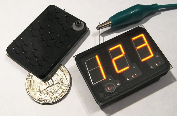
![]()
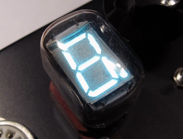
I recently settled on numeral displays for American side of the retro satellite tracker console: the Sperry/Beckman SP-353. It's a gas-discharge display that was developed in 1971 as an improvement upon nixie tubes and sports numerals 0.55" tall. Kind of a pain to drive, but definitely suits the overall aesthetic. I did consider using nixies, but I'm kind of sick of seeing them everywhere!
![]()
On the Soviet side, I'm going to use IV-22 VFDs. They're actually somewhat similar to the SP-353s in driver requirements.
Combining these with assorted American and Soviet indicator lamps and buttons on each side should make for a pretty neat looking result. Finally found some proper Tellite switches for the American side of the console, more on that to come. Still researching what's appropriate for the Soviet side.
Also still trying to decide whether to interface the displays and switches directly to the vintage calculating hardware for each side or use modern hardware as drivers to simplify the interface requirements. I think it may be reasonable to directly interface the transputers with some C012 link chips, but it's really tempting to use an XMOS on the Soviet side to handle all the displays and switches. Decisions, decisions.
-
Transputers?
04/21/2015 at 06:13 • 0 commentsAt some point in planning this project, I stubbornly declared to nobody in particular that the hardware in question had to be era-appropriate and suitably exotic. Preferably something used in spaceflight. Something not commonly found in home or business computing. Something Cold War-era. Definitely not a modern microcontroller.
Enter the Transputer.
Used in spaceflight? Check.
Era appropriate? Check.
Exotic? Double-check.
Transputers were an early technology from the "golden era" of massively parallel computing (say, the early 80s). They introduced some groundbreaking concepts that are still used today, even though not many people have heard of them. I'm not going to dwell on the fine details here, but look 'em up. Also check out their modern descendant, the XMOS microcontroller.
So transputers (the OG ones, not the XMOS descendant) are what's being used on the American side of this beast. The Soviet side will be sporting something a little different, more on that in a future post.
As one of the first steps in this project, I've been re-implementing the Simplified Perturbations Models on INMOS transputers (props to those who have come before me on more standard platforms, and from whose work I'm drawing heavily). The models were published in 1988, the transputers came out in 1985, and the frustratingly-ancient INMOS C compiler I'm using was published in August 1990. As the screenshot attests, making some real progress despite the challenge of dealing with ancient high-tech gear. The code that's complete thus far compiles and is up and running on an emulator, with real transputer hardware hopefully not far behind!
![]()
Keplermatik
Vintage U.S. and Soviet Hardware come together in a Mission Control-style console that actually tracks satellites.


 Imagine that, no Eagle parts libraries out there for INMOS Link Adapters. Quickly remedied.