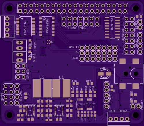
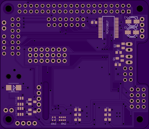
Since my last post on my omnibot rpi hat, I have been doing a lot of testing of my board. With the exception of 3 pins, the design works just as it should. I should have paid closer attention to the data sheet on the pwm i2c led control chips. As you would expect from an led control chip, it is pwm output not input. Sadly I connected my sonar range finders to those chips. A serious oversight on my part.
Additionally, my power system is rather creative. While it is functional, I have taken a step back and decided to revisit it with a new design. When the batteries are depleted, my existing system requires a secondary power supply to power the raspberry pi in order to trigger the relays to charge the system and switch the main power supply to external. This is the equivalent of always needing a jump when you start your car. Whats more is that my power supply was was not very reliable and did not give me the ideal voltages. I decided to utilize the digikey/texas instrument webench design tools to come up with a new solution that offers dual battery charging, 5.2 v output @ 4amps and 6.5 v output @ 2amps.
I have integrated the power supply into the new omnibot rpi pi hat design to further clean up the system. I still need to order the components and get the pcbs manufactured. I need to invest in a decent usb microscope and a hot air gun as well. I have tackled free hand soldering 0805's and SSOP24's by hand, but these 16WQFN may be a bit trickier by hand....
This new design offers io for the following: 2 dc motors, 2 hall sensors, 2 peristaltic pumps, 2 bumper triggers, 2 maxbotix sonar (analog), thermal printer serial control, 2 led, 3 analog input, 1 ir sensor, 1 pwm irled, 1 char lcd i2c module, 1 compass i2c module, 10 pwm servo controls, 1 photosensitive resistor, 2 charging status, 1 button pull, and 1 dht module (I think thats it). It has 3v, 5.2v and 6.5v rails and an integrated power switch. Since my design largely draws on existing adafruit designs/boards, most of the required python packages to run this board are written and well documented.
The new board design is located here:
https://github.com/beetleguise/omnibot_EAGLE

 Jarred
Discussions
Become a Hackaday.io Member
Create an account to leave a comment. Already have an account? Log In.
You should consider selling the HAT. With the addition of the dual battery charger it answers just about every robotics need someone might have with the pi!
Are you sure? yes | no
Interesting thought. After I proto and troubleshoot this board, maybe I will layout another one with a more generic / less specialized layout. Any experience selling boards?
Are you sure? yes | no