Jarred
-
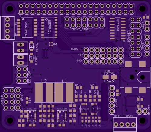
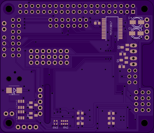
RPI Hat redesign w/ integrated power management
10/19/2015 at 20:04 • 2 commentsSince my last post on my omnibot rpi hat, I have been doing a lot of testing of my board. With the exception of 3 pins, the design works just as it should. I should have paid closer attention to the data sheet on the pwm i2c led control chips. As you would expect from an led control chip, it is pwm output not input. Sadly I connected my sonar range finders to those chips. A serious oversight on my part.
Additionally, my power system is rather creative. While it is functional, I have taken a step back and decided to revisit it with a new design. When the batteries are depleted, my existing system requires a secondary power supply to power the raspberry pi in order to trigger the relays to charge the system and switch the main power supply to external. This is the equivalent of always needing a jump when you start your car. Whats more is that my power supply was was not very reliable and did not give me the ideal voltages. I decided to utilize the digikey/texas instrument webench design tools to come up with a new solution that offers dual battery charging, 5.2 v output @ 4amps and 6.5 v output @ 2amps.
I have integrated the power supply into the new omnibot rpi pi hat design to further clean up the system. I still need to order the components and get the pcbs manufactured. I need to invest in a decent usb microscope and a hot air gun as well. I have tackled free hand soldering 0805's and SSOP24's by hand, but these 16WQFN may be a bit trickier by hand....
This new design offers io for the following: 2 dc motors, 2 hall sensors, 2 peristaltic pumps, 2 bumper triggers, 2 maxbotix sonar (analog), thermal printer serial control, 2 led, 3 analog input, 1 ir sensor, 1 pwm irled, 1 char lcd i2c module, 1 compass i2c module, 10 pwm servo controls, 1 photosensitive resistor, 2 charging status, 1 button pull, and 1 dht module (I think thats it). It has 3v, 5.2v and 6.5v rails and an integrated power switch. Since my design largely draws on existing adafruit designs/boards, most of the required python packages to run this board are written and well documented.
The new board design is located here:
https://github.com/beetleguise/omnibot_EAGLE![]()
![]()
-
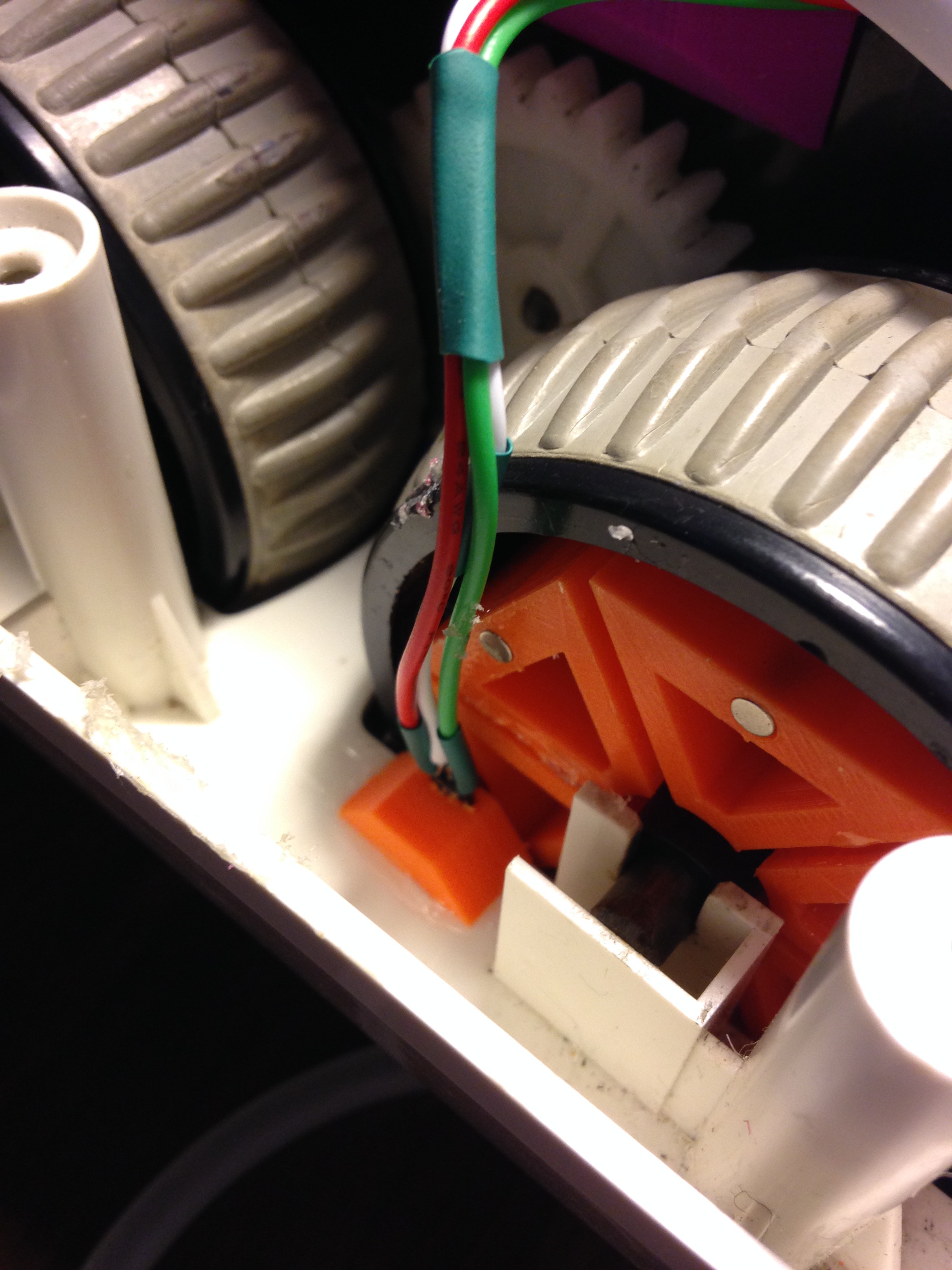
Wheel Encoder
09/27/2015 at 21:33 • 0 commentsI incorporated a simple wheel encoder the the left and right rear wheels using Hall effect sensors. Six 3D printed brackets holding small rare earth magnets were glued between the existing spokes of the left and right rear wheels, and a small bracket positioned the hall effect sensor in an ideal space. This system breaks each side wheel down to a six quadrant system and allows for more precise motor control. This is a minimally invasive solution to drive precision that allows for the use of existing original omnibot hardware.
![]()
-
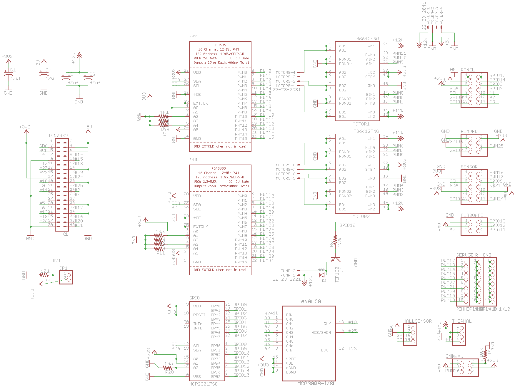
Raspberry Pi omni-"Hat"
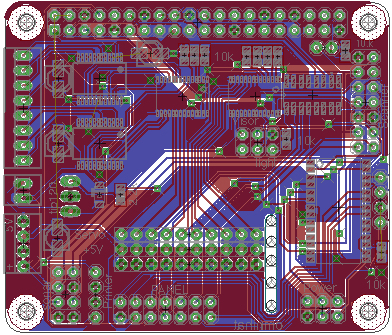
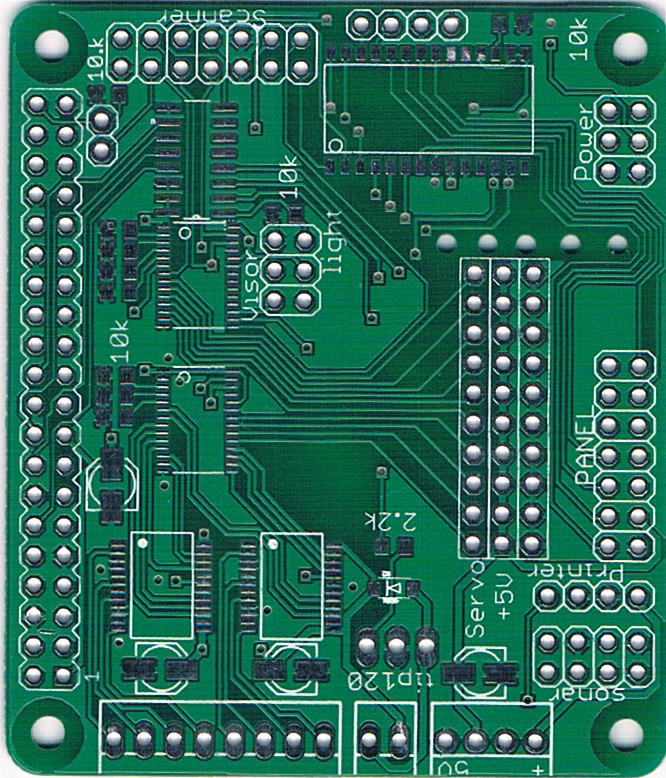
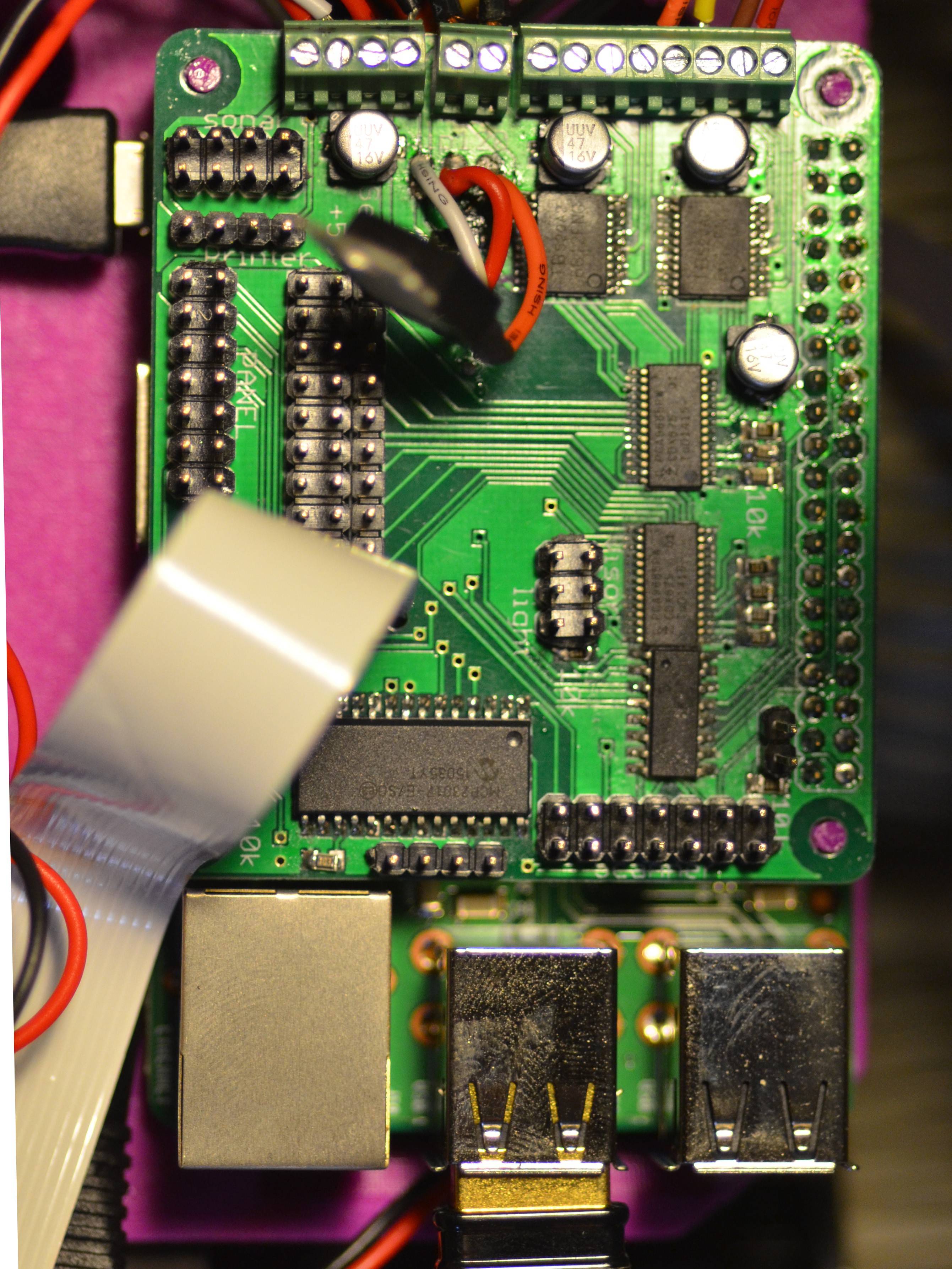
08/10/2015 at 22:57 • 0 commentsA custom "hat" was was designed for omnibotler based on a combination of existing Adafruit hats and specific requirements. This hat incorporates the following chips: PCA9685 (2x), TB6612FNG (2x), MCP23017, and MCP3008, and provides pinouts for 1x stepper motor, 2x dc motors, 1x pump, 12x servo, 4x analog sensor, 1x Tx, 14x gpio, and 4x pwm. The pinout of the tip120 was incorrect in the board layout and required re-routing after the pcb was ordered. Pinouts are grouped based on functionality and/or subgrouping. This simplifies wiring and the connection of discrete portions.
(This was my first attempt at hand surface mount soldering and ordering manufactured boards, so please excuse the sloppy execution/ poor silkscreen. )
![]()
![]()
![]()
![]()
-
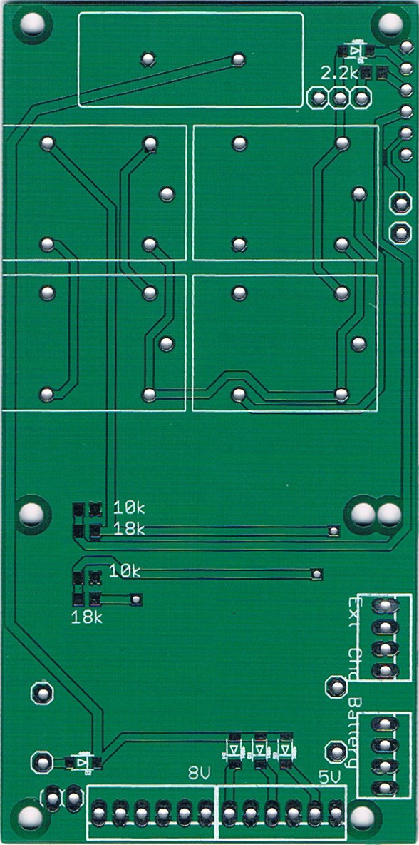
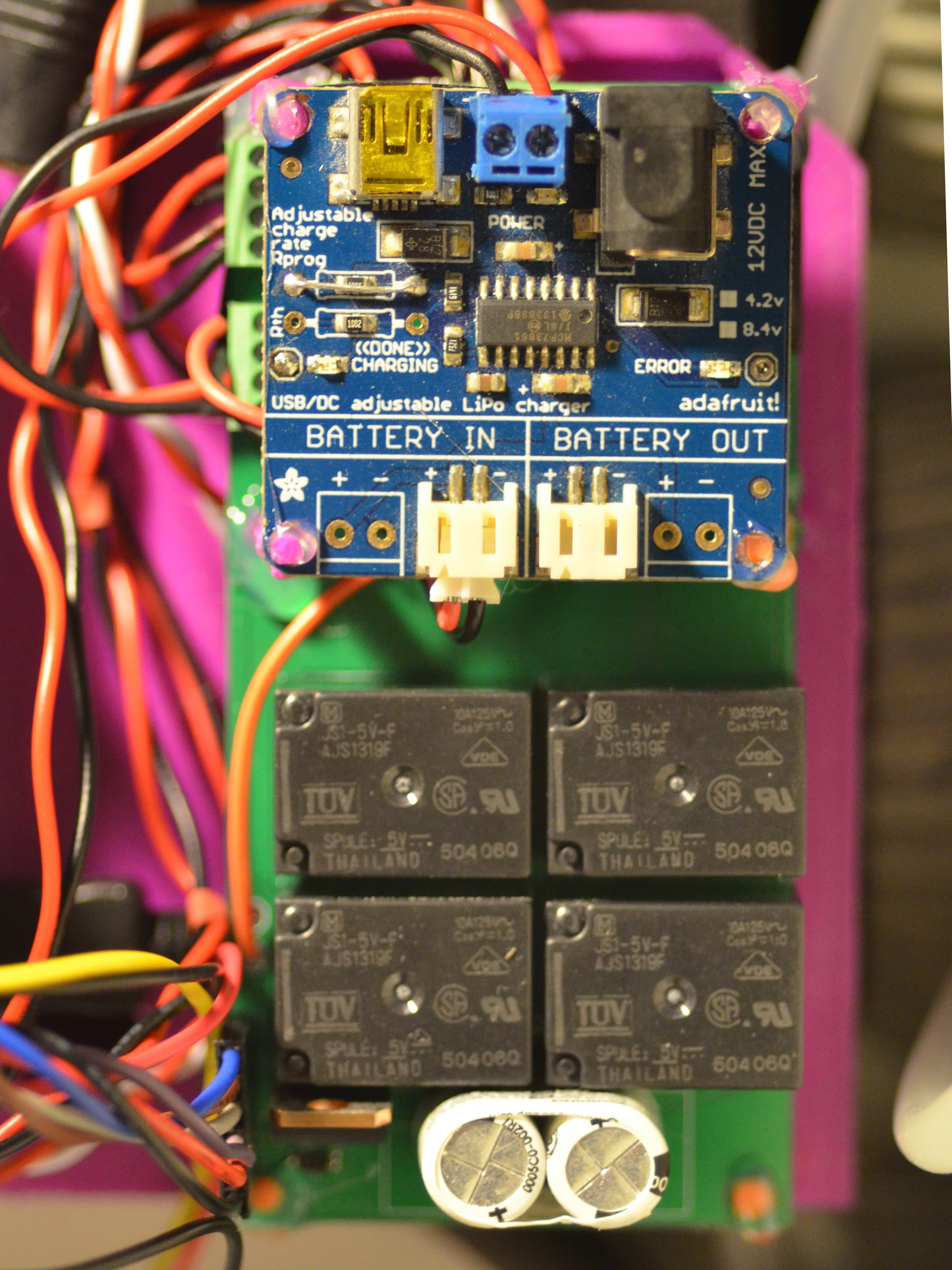
Power Management System
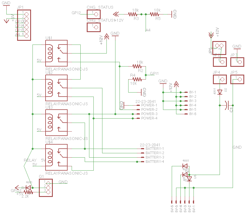
08/10/2015 at 22:56 • 0 commentsI have taken a rather circuitous approaches to robot charging and power source management for this project. 5v and 8-9v power is supplied and regulated by a custom board that utilizes four spdt relays to switch the power source from 2x 6600 Mah 4.2V lithium ion battery in series to an external source that charges the batteries in parallel and supplies powers. A 2.5F cap acts as a 5v supply "ups" to ensure the raspberry pi continues uninterrupted when switching. This board utilizes a depreciated Adafruit lithium polymer dc charger (MCP73861) and a hobby 5v ubec. It provides 3x 8-9v supply , 3x 5v supply, and pinouts for charging status, external power supply status and relay switching.
![]()
![]()
![]()
Omnibotler
Updating an Omnibot 5402 to serve as a home automation hub and home "assistant"