 Dave Pedu
-
Base / Switch Details
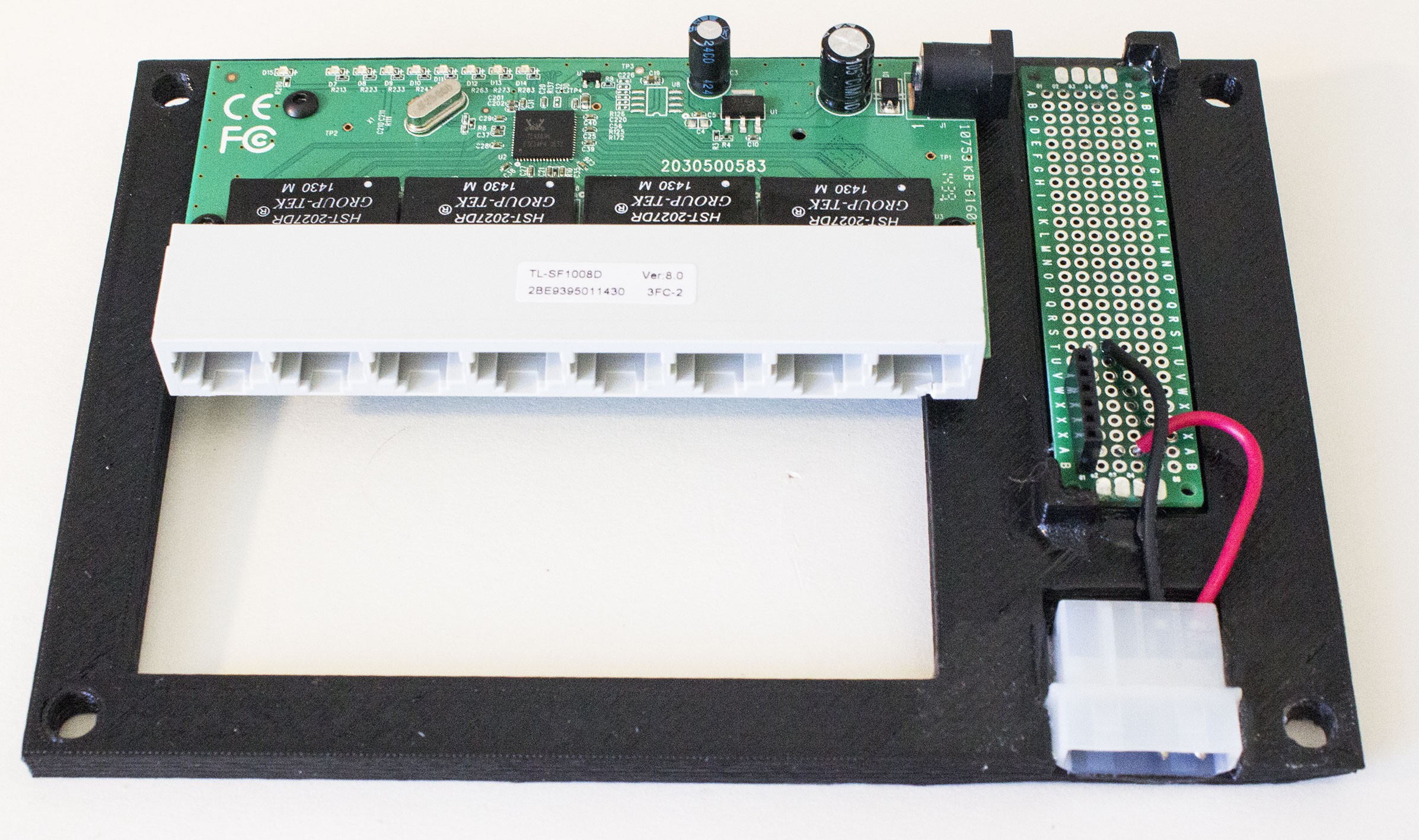
04/26/2015 at 20:04 • 0 commentsThe bottom most layer of the Pi Rack mounts an ethernet switch and some simple connections to bring power up to the Pis.
![]()
Wanting to keep things simple, I decided to use an ATX power supply for now, as they provide a steady 5v power source good enough for computers, so powering a Pi would be no effort. The 3d printed bottom piece has recesses for the molex connector and a piece of prototype board (it's oversized because I wanted space for future additions - maybe a simple fan controller if needed). All that's really here is a SIP socket that power/ground is connected to.
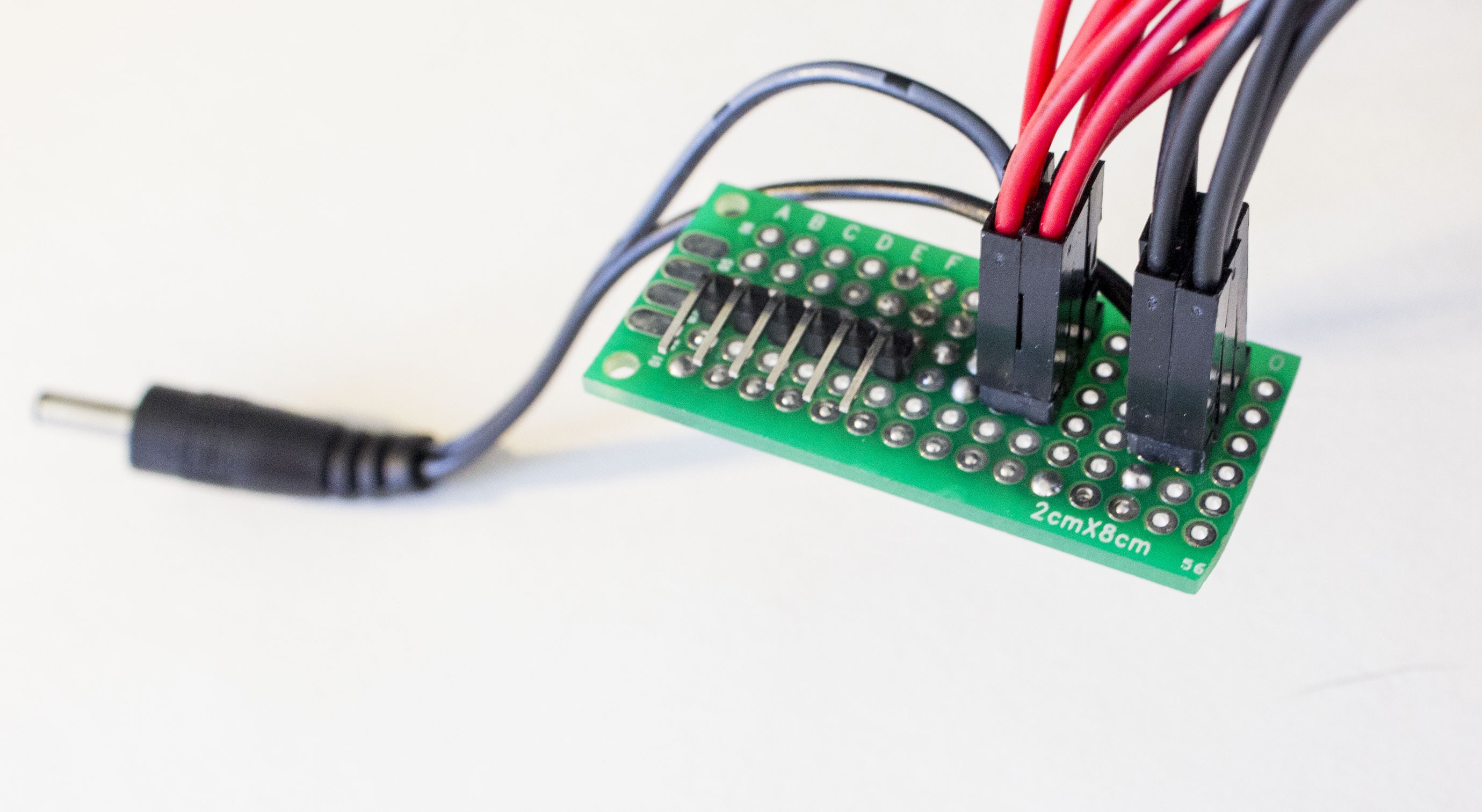
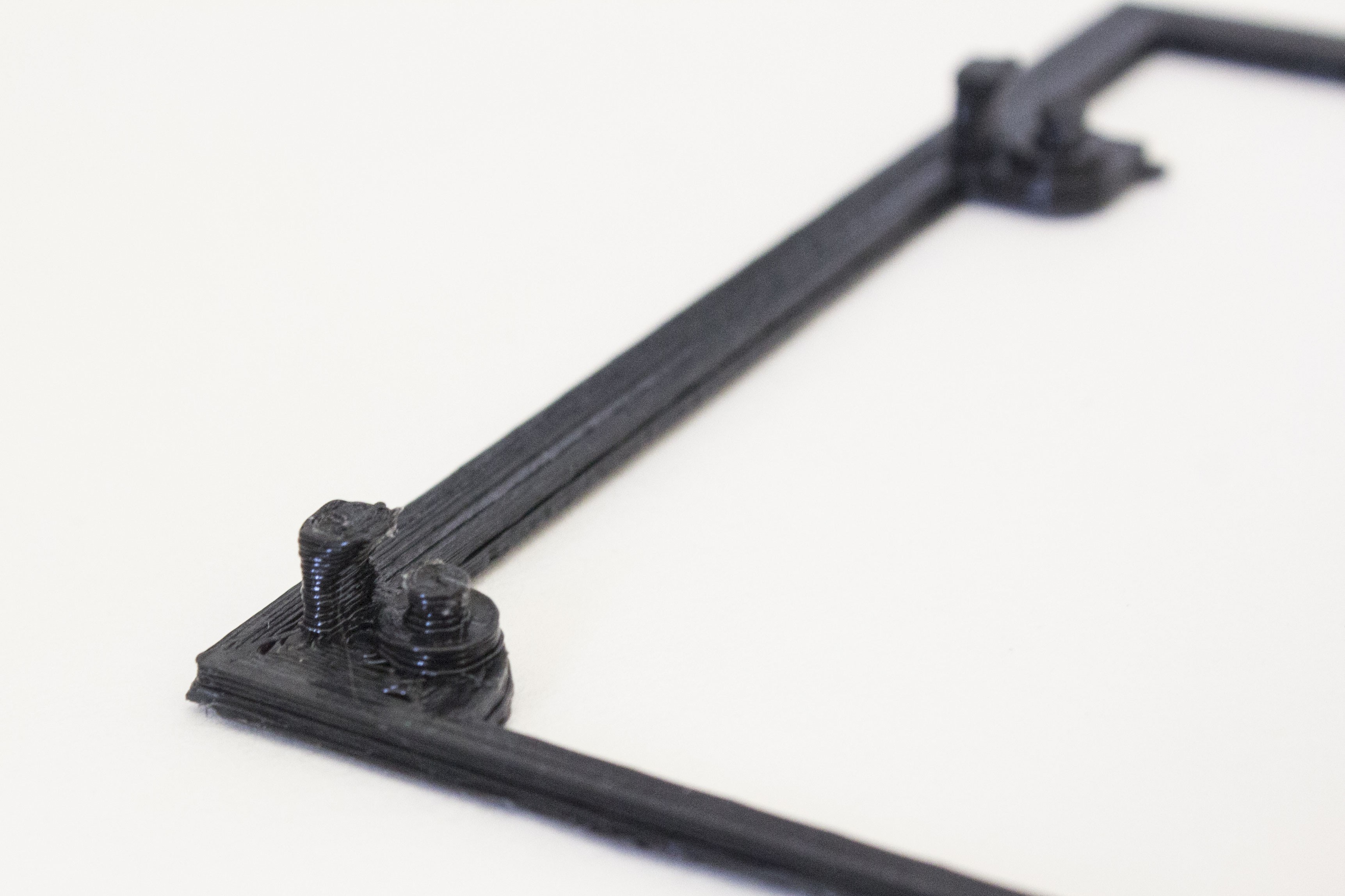
![]() To connect to the power-providing SIP socket, this little right angle breakout board provides a pin for each PI, the jumpers are simply plugged into this. I also cut the switch's original power supply cable and resoldered it here so its powered entirely from one supply.
To connect to the power-providing SIP socket, this little right angle breakout board provides a pin for each PI, the jumpers are simply plugged into this. I also cut the switch's original power supply cable and resoldered it here so its powered entirely from one supply.This connects to the bottom socket something like this:
![]() What's neat about this is I can experiment with different power sources in a fairly modular way - just need a 6 pick SIP socket.
What's neat about this is I can experiment with different power sources in a fairly modular way - just need a 6 pick SIP socket.![]()
All that's left is to flip the base over and bolt it in place! An opening gives easy access to the ethernet connections, and spare ports for the uplink.
-
Hotswap enclosure details
04/26/2015 at 19:42 • 0 commentsThe core of this project is figuring out how the Pis will slide into place and have all the necessary ports line up and make contact. Designing the sled gave me a firm grip on the capabilities of my printer, so creating the backplane was next. Having little 3d modeling experience, I turned to the simplest tool available: SketchUp.
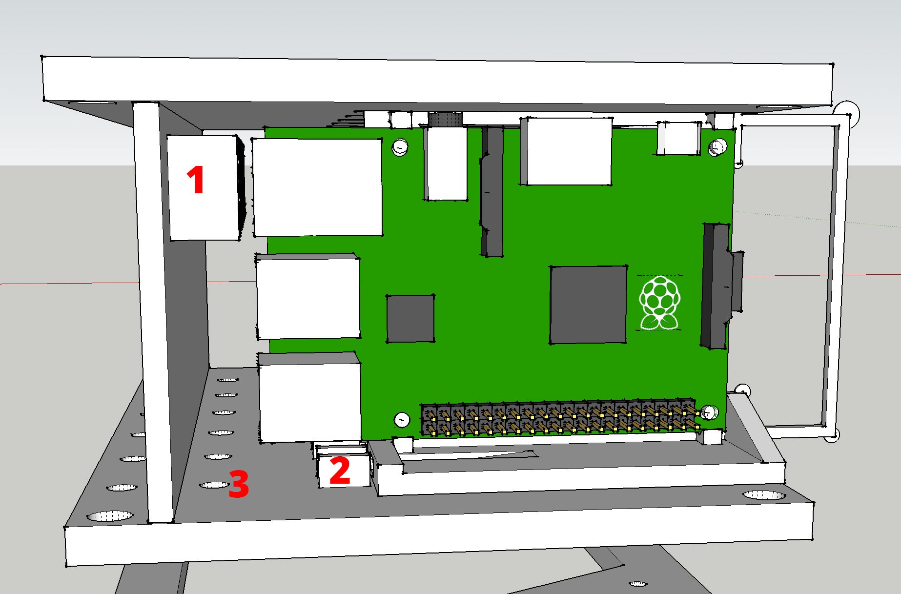
![]()
I found a reasonable accurate model of the Pi B+ online, so I used that to mock up the enclosure. Label 1 is a housing for the ethernet plug. Originally I planned to epoxy these into place, but force-fitting them into the 3d printed model seems sufficient. My cheap printer tends to round corners but in this case it only helps hold the RJ45 connector in place. Label 2 is a U-shaped holder for two more breadboard jumper wires, the female end of which is glued in place. The power and ethernet wires all run down through the hole at Label 3, down to the layer where the ethernet switch sits and power will be distributed. The vertical back is fixed to the top/bottom layer with a tongue and groove.
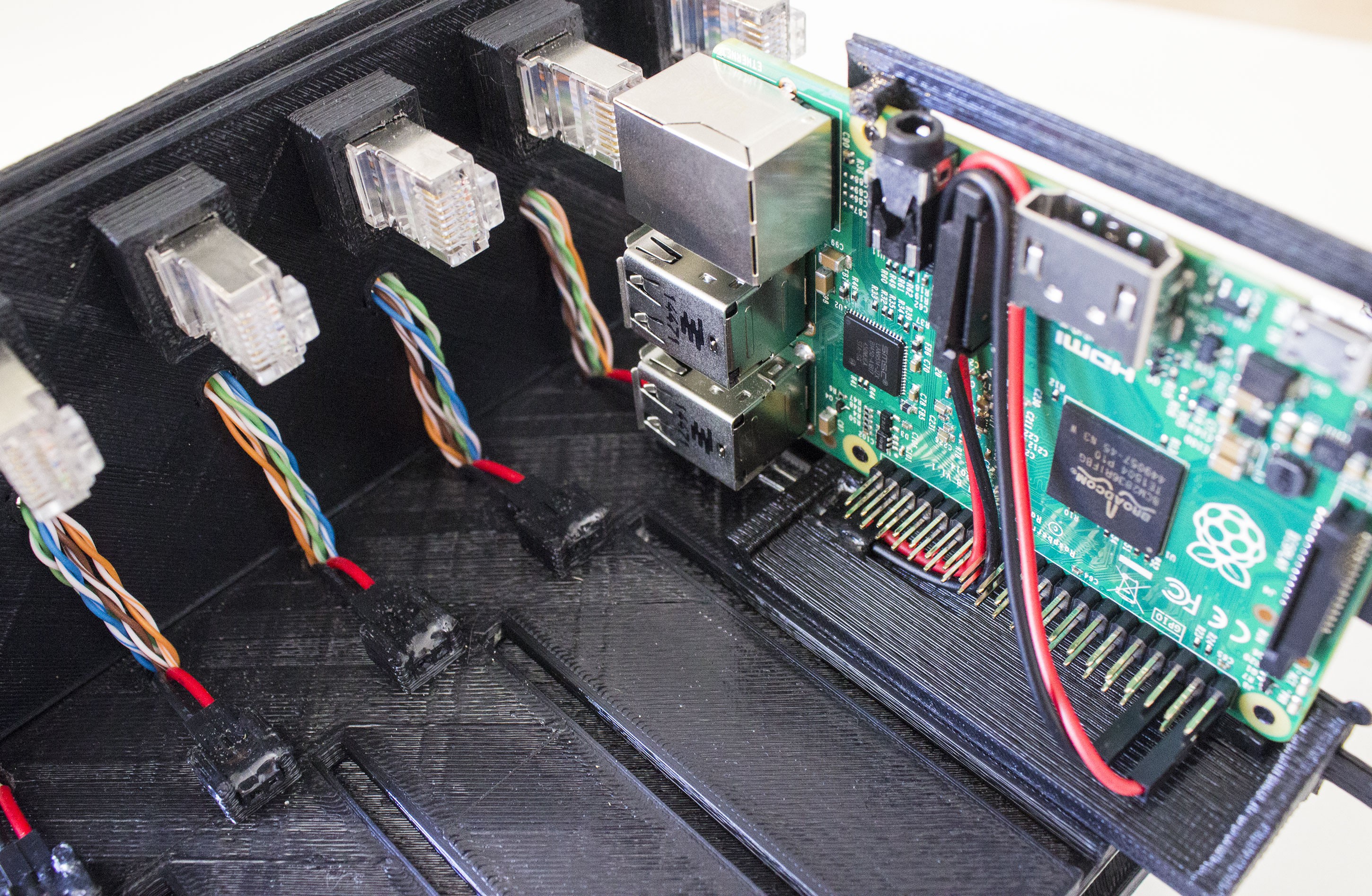
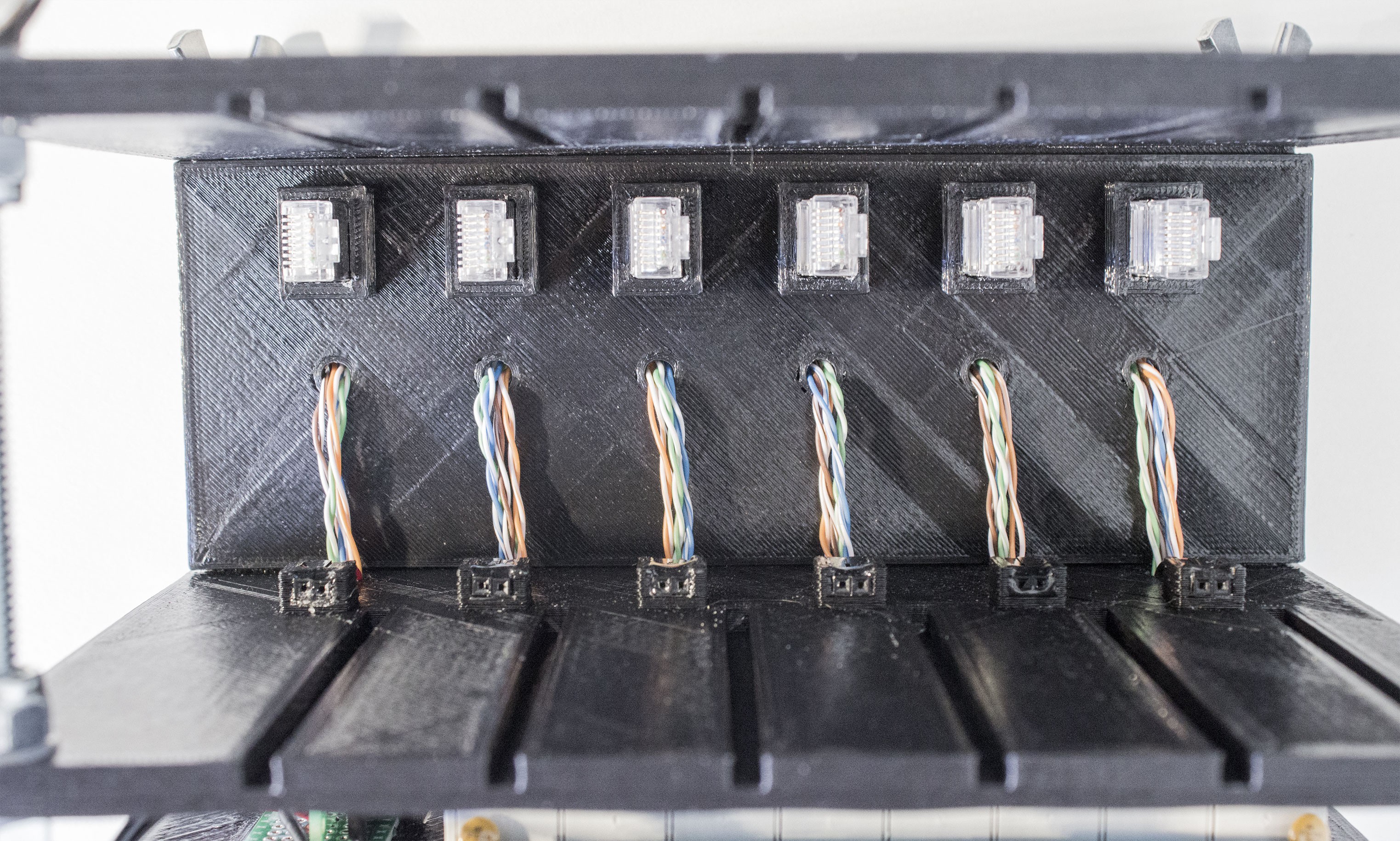
A keen observer would note that in the model pictured above the ethernet wires would have to run through separate holes in the back. I ended up printing the bottom layer first and forgot these holes! I compensated by adding new holes in the rear vertical piece. This is a little more clear when seen here, with a Pi inserted and the top removed:
I think I like this routing of the ethernet wires, they're a little more protected than the original design. There's room for some simplification here - I could have omitted two twisted pairs of each ethernet run here too - the Raspberry Pi only supports 10/100 lan, which only needs 4 wires - only gigabit ethernet uses all 8. In fact, my switch is only 10/100 as well. But I left them in under the idea of futureproofing. I would LOVE to see a Pi with gigabit support someday.![]()
Assembled with some simple threaded rods, lock nuts, and wing nuts from my local hardware store, the Pi bay looks like this:
![]()
-
Sled details
04/26/2015 at 19:12 • 0 commentsEach Raspberry Pi sits on a custom 3d-printed sled. The original model B/B+ and the Raspberry Pi 2 have an identical form factor, so it works for both!
![]()
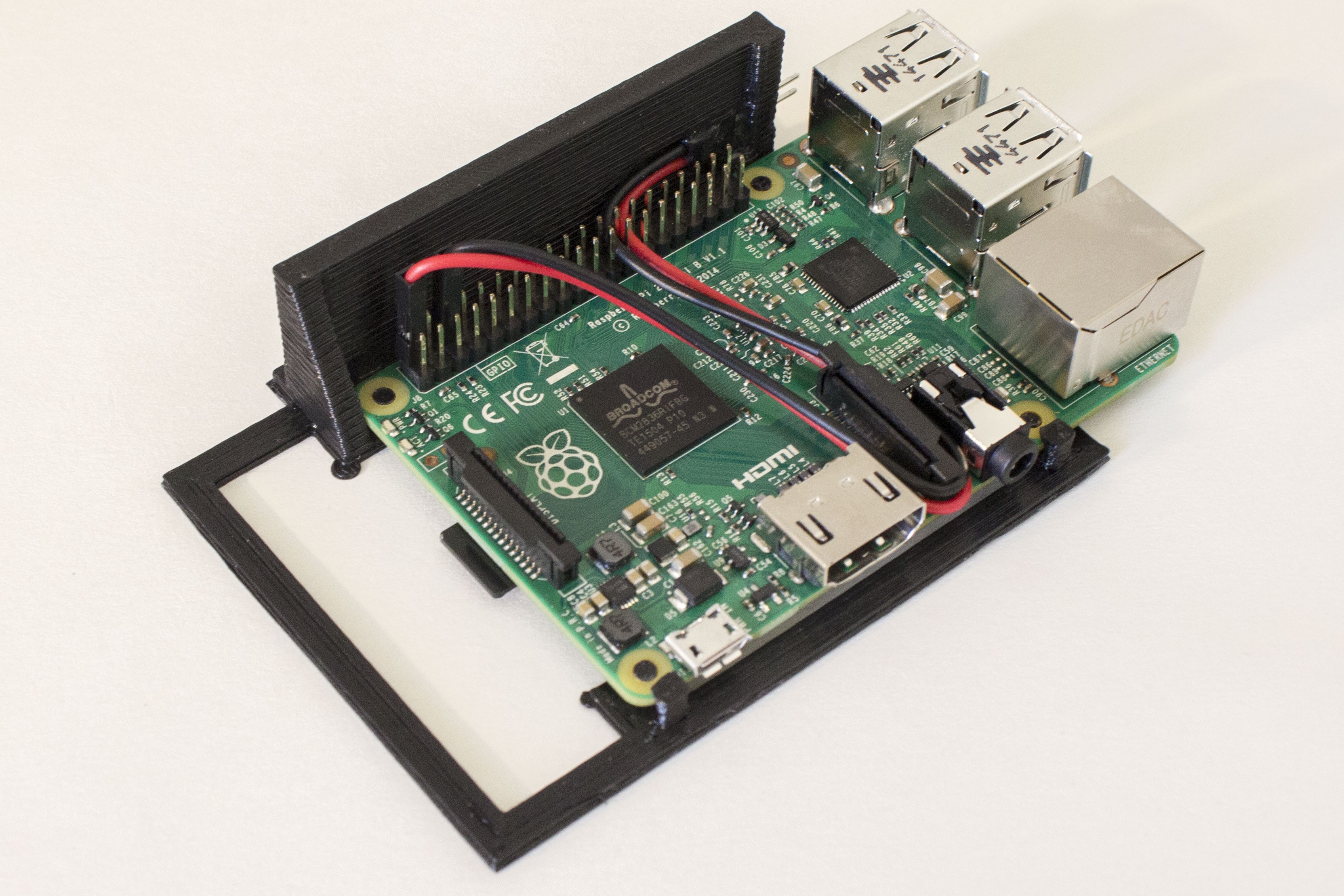
Leftover breadboard jumper wires are connected to the GPIO pins the Pi to provide power, with the other ends glued to the sled. Power and ethernet are really the only connections I care about in this project, as the Pis will be ran headless. The Pi can be powered by these GPIO pins using any 5v source, but it bypasses protections on the usb micro power supply port, so care must be taken that the power supply is within what the Pi accepts, and polarity is correct. The Pi wants between 4.75V and 5.25V (less than this, or drops, can trigger the B's brown out detector - details here: https://www.raspberrypi.org/forums/viewtopic.php?t=58151)
The sleds are completely screwless - pegs printed into them fit the RasPi's mounting holes, and little clips hold the Pi in place.
![]()
This is my first adventure into 3d printing, and getting the sled just right took literally a dozen iterations. To figure out what my very low end 3d printer was capable of, figure out the easiest way to mount a Pi, how to run the power, etc.
 To connect to the power-providing SIP socket, this little right angle breakout board provides a pin for each PI, the jumpers are simply plugged into this. I also cut the switch's original power supply cable and resoldered it here so its powered entirely from one supply.
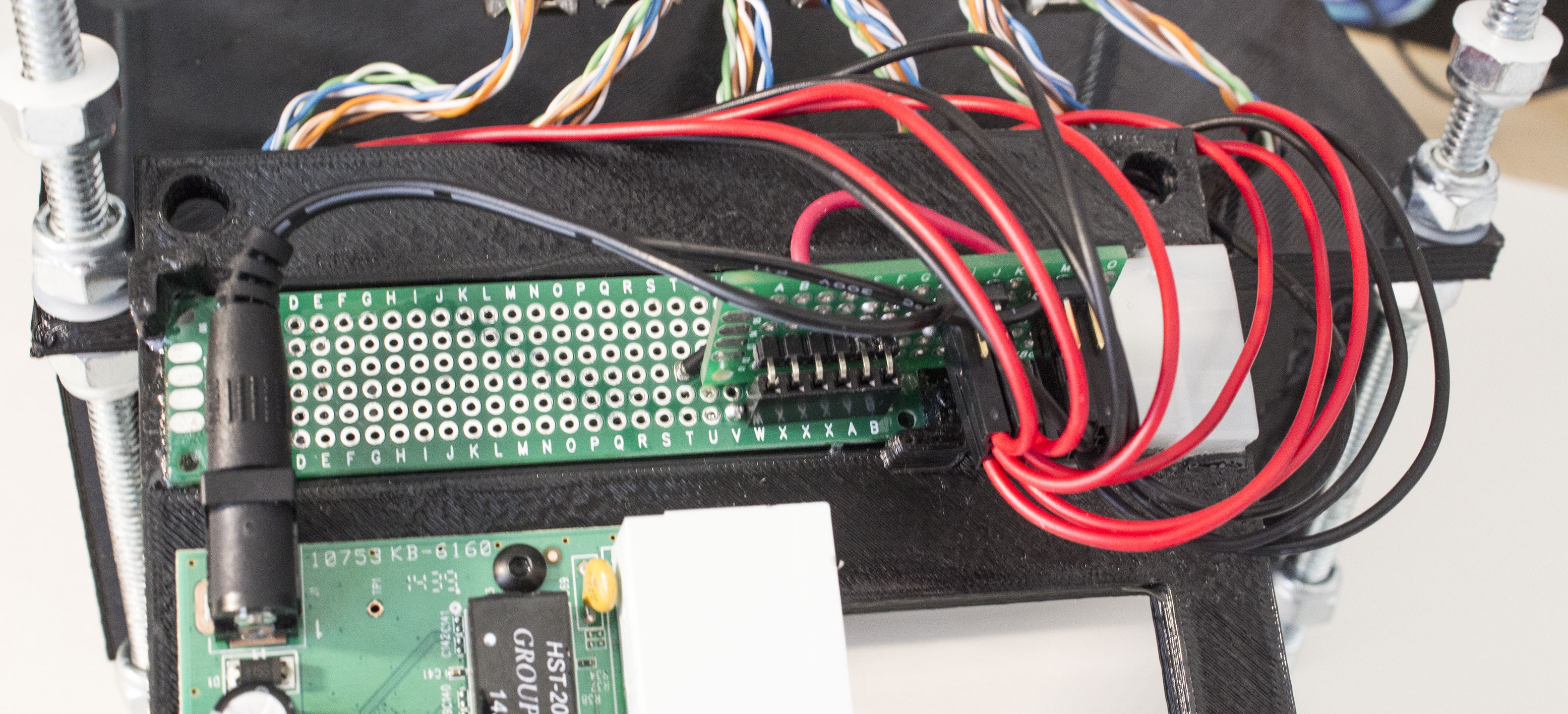 What's neat about this is I can experiment with different power sources in a fairly modular way - just need a 6 pick SIP socket.
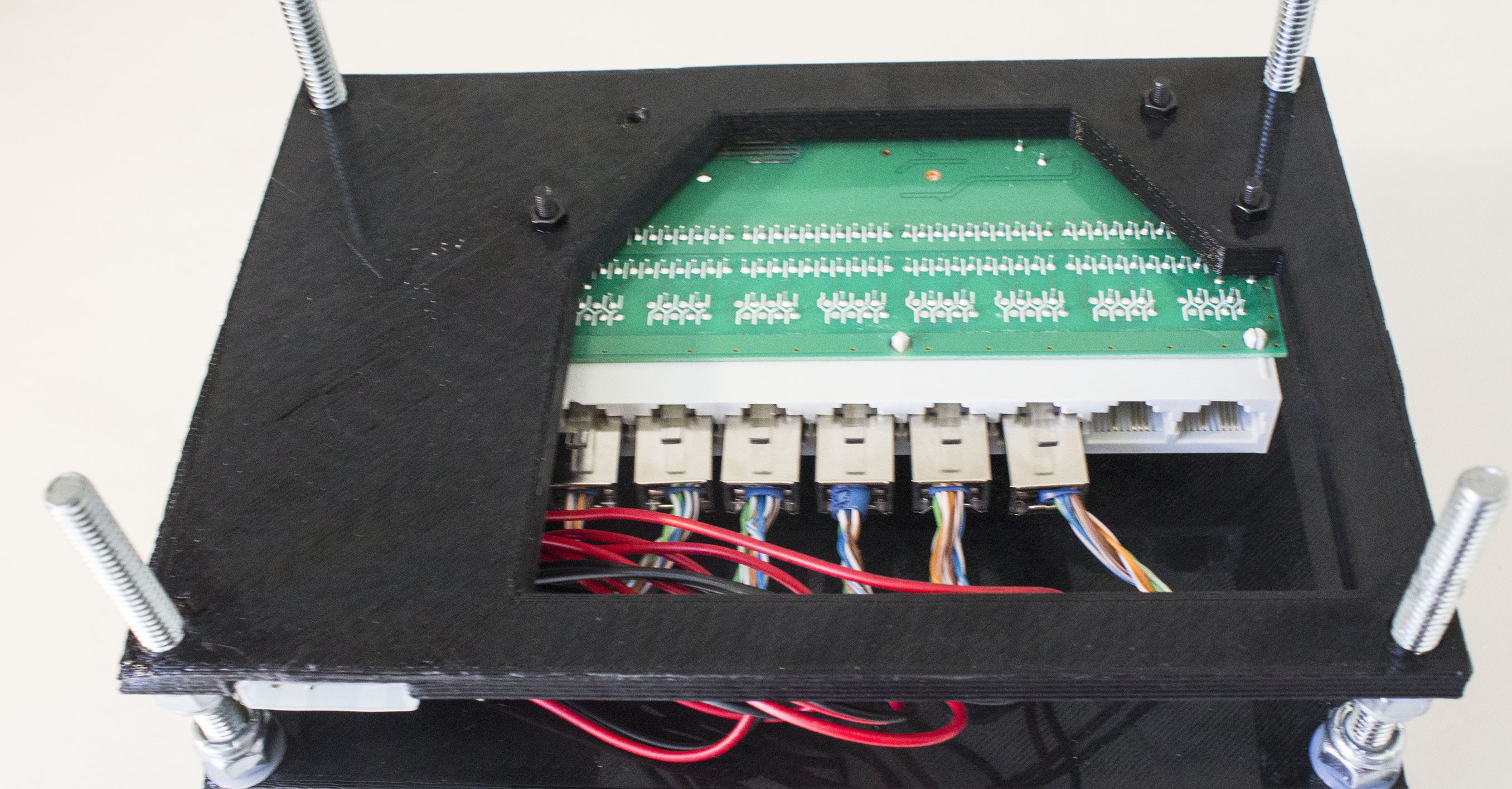