 Radu Motisan
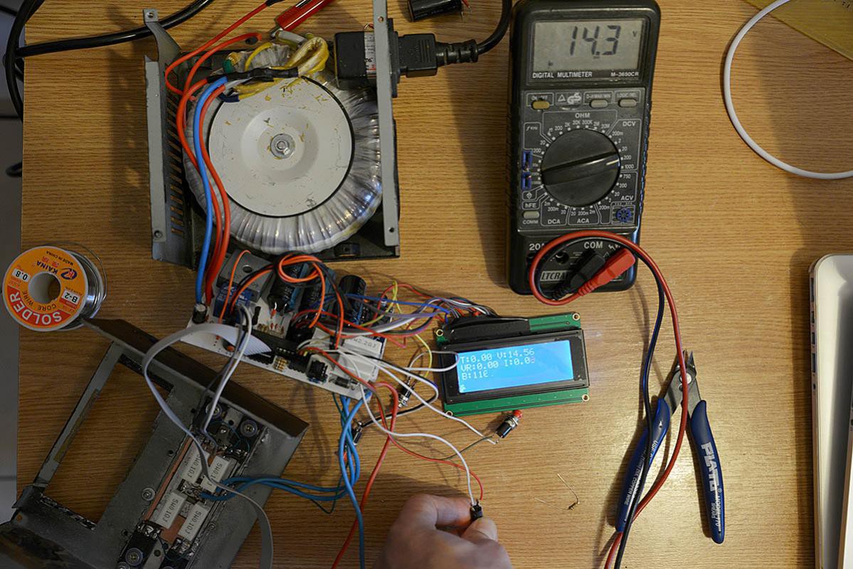
ADC on port PC4 is used to read output voltage through a 10K/100K resistive divider. PC5 is connected to the shunt and used to read the current.
I measured the transformer output, immediately after the filter capacitors following the rectifier. I get 16.1V with the center tap and 33.8V on the full secondary. With full output, using the TL082, I only get 14.56V vs 16.1V and 26.26V vs 33.8V.
 |  |
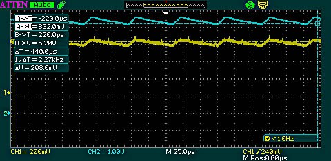
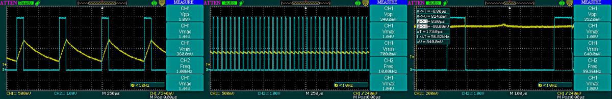
Finally the PWM code is in place, and I can now adjust not only the duty cycle, to vary the DAC output from 0 to 5V, but also the frequency. I wanted to see the ripple. So I connected the oscilloscope , CH1 (yellow) on the RC low pass filter capacitor and CH2(cyan) on the OpAmp output, right where the signal goes to the base of the power transistors.
The only problem is ADC can do a single conversion at a time, so we need to measure voltage and current alternatively since we use two separate ADC channels for that. A 16Mhz crystal is used with the Atmega8 and an ADC prescaler of 128 to increase the conversion speed to maximum. Here's the code logic:
1) Initialization
float vref = 5.0;

#define MODE_MEASURE_CURRENT 0
#define MODE_MEASURE_VOLTAGE 1
volatile bool adc_mode = MODE_MEASURE_CURRENT;
volatile float current = 0, voltage = 0;
// setup ADC to measure as interrupt: go for current first
adc_mode = MODE_MEASURE_CURRENT;
ADMUX = PC5;
ADCSRA = (1<<ADEN) | (1<<ADIE) | (1<<ADIF) | (1<<ADSC) |
(1<<ADPS2) | (1<<ADPS1) | (1<<ADPS0); // set prescaler to 128 (16M/128=125kHz, above 200KHz 10bit results are not reliable)
sei(); 2) interrupt
// Interrupt service routine for the ADC completion
// we measure the current (PC5) and the voltage (PC4) alternatively
ISR(ADC_vect){
  uint16_t analogVal = ADCL | (ADCH << 8);
  if (adc_mode == MODE_MEASURE_CURRENT) {
	  current = (analogVal / 1024.0 * vref) / 0.55;
	  // alternate mode
	  adc_mode = MODE_MEASURE_VOLTAGE;
	  ADMUX = PC4; // next time we will do ADC on PC4, to get the voltage
  } else if (adc_mode == MODE_MEASURE_VOLTAGE) {
	  float R14 = 10, //10k
			R13 = 100; //100K
	  voltage = analogVal / 1024.0 * (R13 + R14) / R14 * vref;
	  // alternate mode
	  adc_mode = MODE_MEASURE_CURRENT;
	  ADMUX = PC5; // next time we will do ADC on PC5, to get the current
  }
  // Not needed because free-running mode is enabled, so the convertion will restart by itself
  // start another ADC convertion
  //aux_ADCReadIntr(PC5);
  // ADCSRA |= 1<<ADSC;
  ADCSRA = (1<<ADEN) | (1<<ADIE) | (1<<ADIF) /* | (1<<ADFR) */ | (1<<ADSC) |
  				(1<<ADPS2) | (1<<ADPS1) | (1<<ADPS0); // set prescaler to 128 (16M/128=125kHz, above 200KHz 10bit results are not reliable)

 }
Next thing to do is to test the supply for a shortcircuit! In the interrupt code, right in the if (adc_mode == MODE_MEASURE_CURRENT) { , if the current is dangerously high I need to reduce the DAC by lowering the duty cycle, to limit the output. How fast can this be done, is something we need to see.fingers crossed...
Discussions
Become a Hackaday.io Member
Create an account to leave a comment. Already have an account? Log In.