-
CO sensor reading
09/21/2015 at 18:34 • 0 commentsThe next part of my project is focused on reading the CO senor. The CO sensor I am using is the Hanwei MQ7 (data sheet: https://www.sparkfun.com/datasheets/Sensors/Biometric/MQ-7.pdf).
The CO sensor requires a 5v power supply that may be provided with a 5v fixed regulator or the 5v pin of the micro-controller. The more difficult part to control is the heater element that requires a shifting voltage to toggle between 1.4v and 5v. Fairchild semiconductor makes a Adjustable/Fixed voltage regulator that is a fixed 5 volts when no controller resistor is hooked up to the control pin and between 1.25v and 32v when the resistor is active on the control pin. By using a solid state relay we can isolate the adjustment pin of the regulator to provide our 5 volts when the relay is open and 1.4 volts when the relay is closed and connected to the the proper resistance value. I just used a 50k trim pot to speed the implemenaation up.
-
CAD for HAD
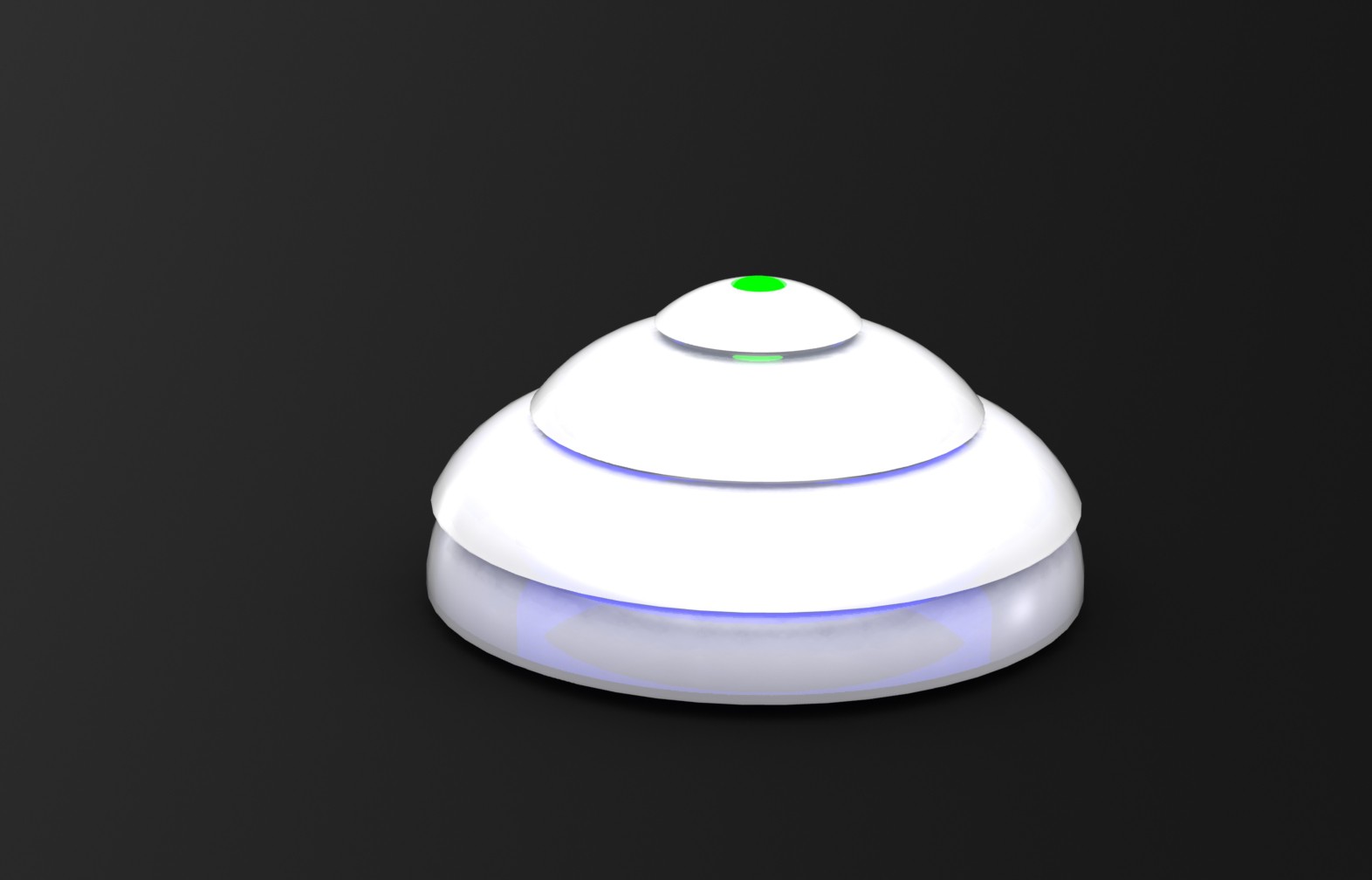
09/18/2015 at 00:04 • 0 commentsI drew something up in SolidWorks to get an idea of the outer shell. Right now I am thinking of a layer cylindrical shingle design. This would allow the enclosure to shed water, but would allow air interchangeability for the air quality sensors.
I added as top status indicator light and an internal light pipe that would probably look really cool if it was running a color flow sweep. If these parts were injection molded it may have to multiple snap together pieces, but I am noddling around with some other ways to make moldable lover vents that can utilize one die set.
-
Wireless Sensor Proof of Concept
09/10/2015 at 17:15 • 0 commentsI am still waiting on my parts to come in for my Gas senor build, but thought that lack of proper parts should not stop my progress so I decided to press on. What I wanted was a prof of concept that I could implement a user monitoring system and add functionality to the system to allow user queries and interaction. I had a water moisture senor handy so I decided to make a sink leak detector (or water heater, or AC, or whatever you want to stay dry).
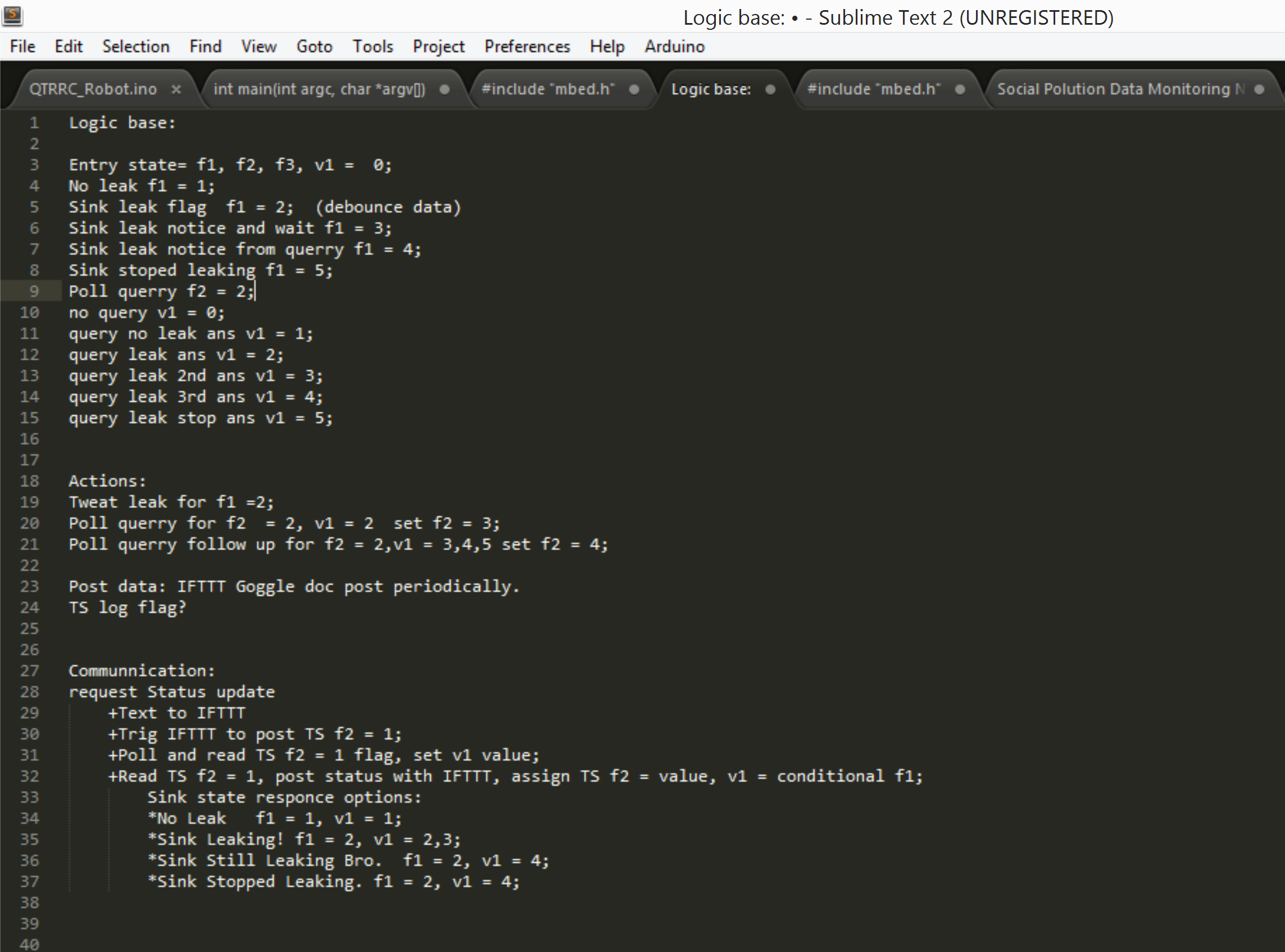
First step was figuring out the tools. I have been using a mBed Freescale Freedom board as my prototyping controller since it works well with my ESP 8266 wifi board, and the water sensor seems happy at 3 volts. For the web interfacing and UI I decided to go with what I have been using so far and that is ThingSpeak and IFTTT. ThingSpeak is a great place to dump, log and read data with simple HTTP requests. IFTTT is a great API linker that has a maker channel that can allow your controller to interact and post to just about all forms of social medial and communication. Once the tools were identified I need to map out the controller logic. The primary goals I had for this leak detector were to send out an initial leak notice as soon as a leak occurred, while still allowing the user to poll the leak detector status on demand. Just to try two methods I decided to use twitter to post the initial status and phone text messages to take in poll requests and send updates back to the user. Below is a map of the basic pseudo code I wanted to use. I did not end up using all of the variable flags as it adds complexity, but you could get more than one data point if you wanted to.
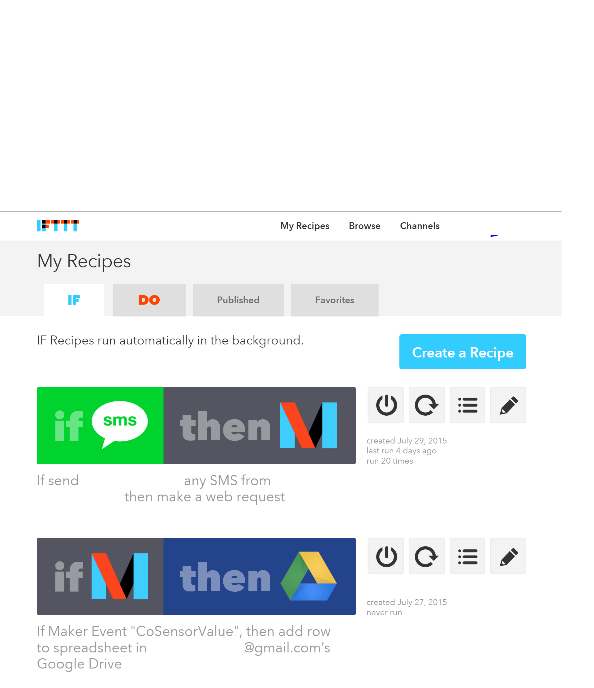
Once the base logic was figured out I began to implement the code on the mBed online compiler. I already have libraries for IFTTT, ESP 8266 and HTTP that I hacked into my code, I say hacked, because it was not the cleanest of jobs. One I got those libraries linked correctly I pasted in my simple loop to test the moisture read from my Freedom board's analog pin. I set the leak event to be triggered over a 30% moisture level. I noticed that just touching the sensor could get values of up to 25%. The initial twitter post was taken care of with a single post to a recipe I created in IFTTT to tweet a leak notification when the IFTTT url is pinged by my microcontroller via the ESP 8266.
![]()
The user query part of the code was more complex. I used IFTTT to post a text flag to ThingSpeak everytime I sent a text to IFTTT. My code scans ThingSpeak to look for this flag, when it sees it, the code goes into some if statements to set the appropriate state response. Once the response is text sent the code writes over the Text flag in ThingSpeak and continues to wait for more requests in an endless loop.
It took a few tries of code tweeks, but the leak detector ended up working pretty well. I got a battery back and USB backup battery to plug into my boards and ended up making the device fully portable. I am not sure if I would do this as a final implementation, but I was fun to see it working truly wireless.
The next steps will be implementing a similar protocol with my Gas sensors, once they are working to get them to post real time air Quality data.
-
Project Video
08/17/2015 at 19:42 • 0 commentsHere is my overview of the project progress so far. This was a bit hard to get out as internet is super sketchy here in Hawaii.
-
Go ESP go.
08/16/2015 at 07:05 • 0 commentsThis is pretty exciting, got my ESP to do some cool stuff. If you have not heard of iftttt.com you should check it out ASAP. IFTTT is a great little API linker that lets you hook your IOT device up to the web. So far with this website I have been able to get my freescale freedom board to Tweet me, Text me and e-mail me. I ca even get it to post logged date to a google spreadsheet. The secret behind making all these tests fairly easily is IFTTT's Maker channel. With the Maker channel you can generate a url to ping that will set off a set pre selected event. The interface is so easy that you could set up one of these events in under 5 minutes. I also have been looking at Thingspeak and PubNub. So far I have been able to trigger events on thingspeak with cURL (such a great tool), but I have not gotten my board to play nice yet. The whole point for trying a secondary IOT service is to test my ability to talk back to my board. If I can dump date to fields in thingspeak, I can have the ESP chip ping the thingspeak channel and take action when it sees the appropriate flag.
![]()
-
ESP can not live on breadboard alone.
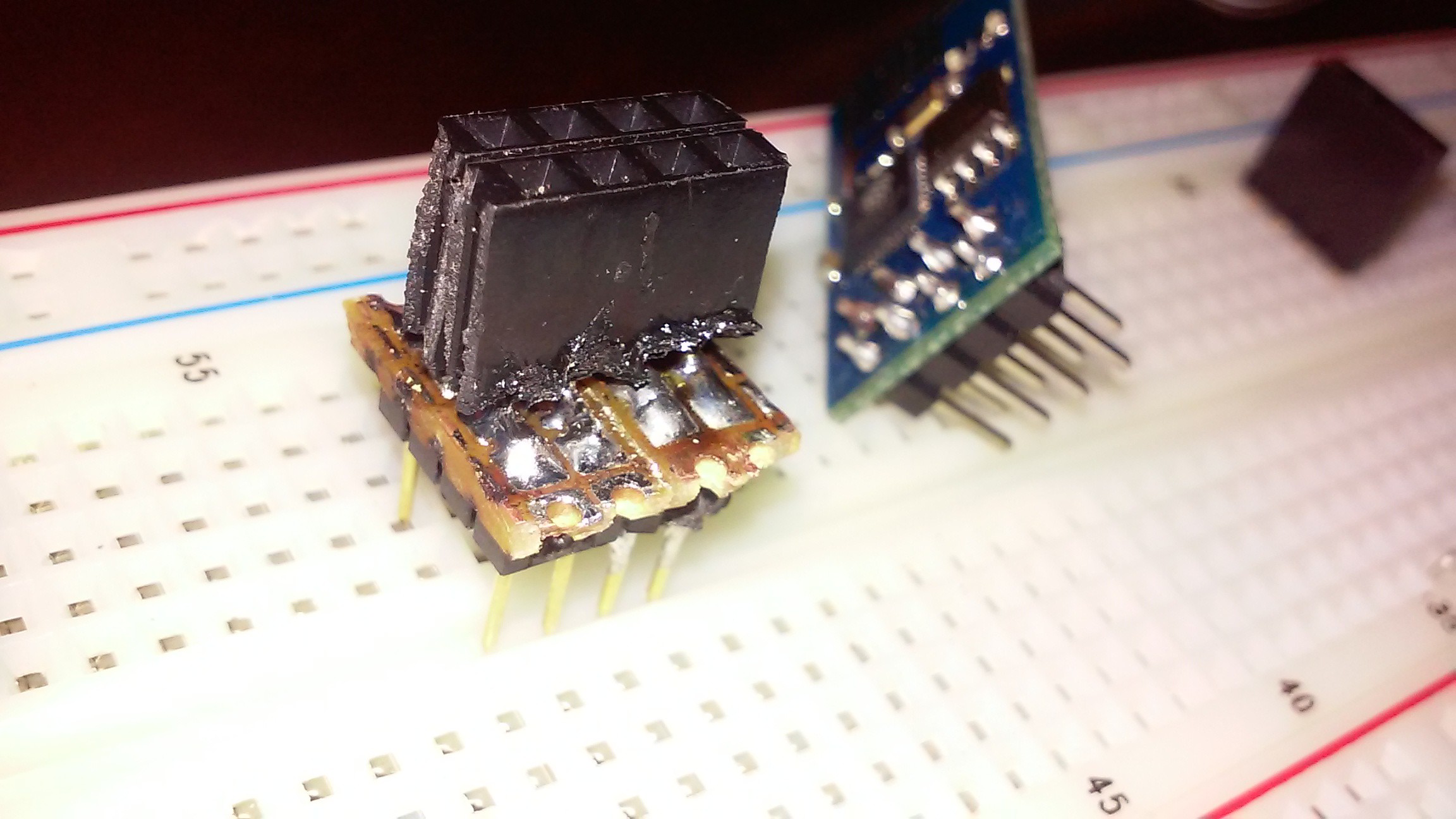
08/09/2015 at 22:21 • 0 commentsI would like to give a little more detail on my progress so far. The first hurdle I had had was connecting the esp 8266 to the board, easiest way to protype this thing chip is to make a breadboard connector so you can hook the chip up the the wider pin spacing. After some tight soldering I was able to get my adapter working.
![]()
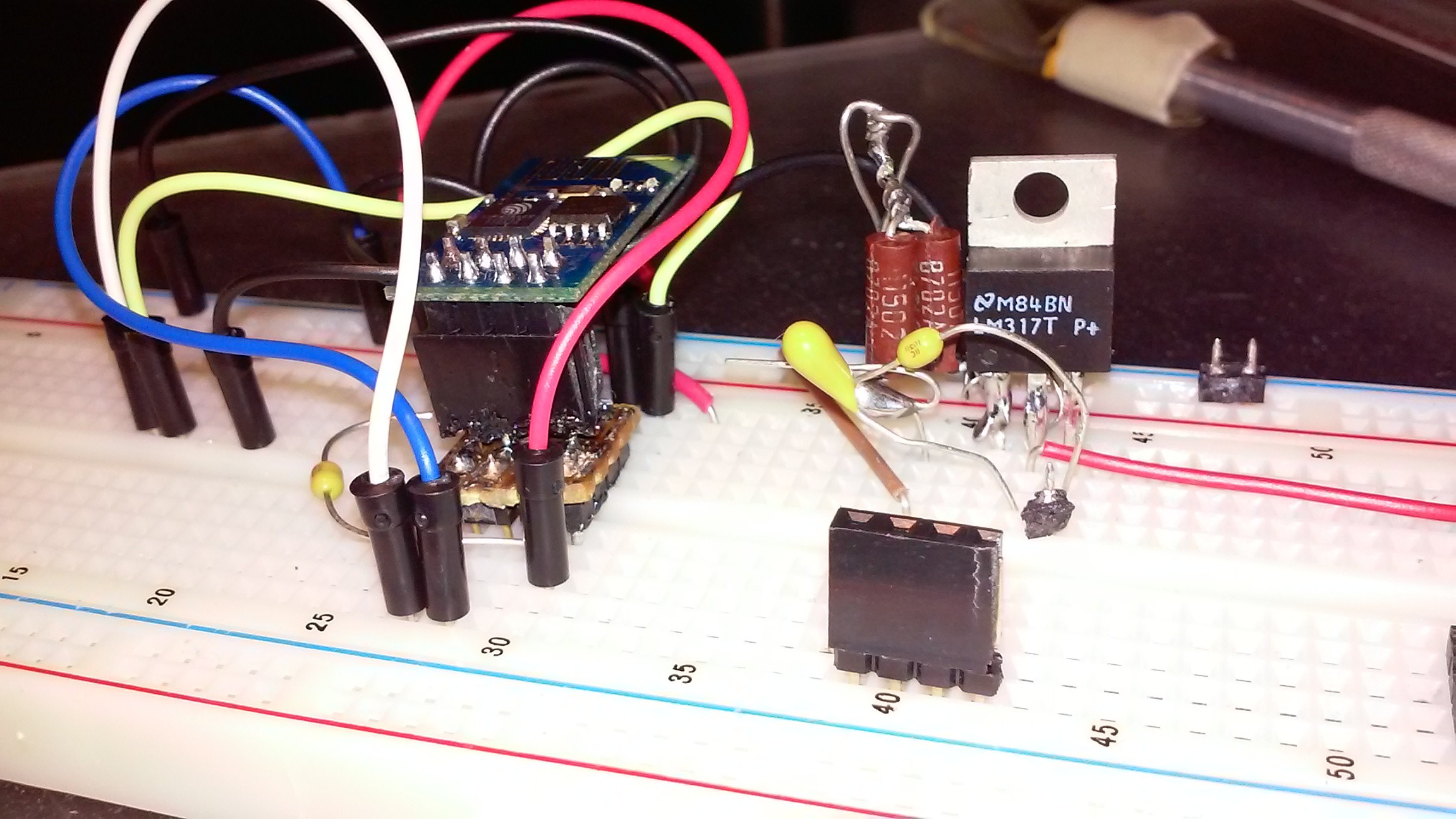
Once I had a way to hook up to my breadboard, the next step was to get my ESP power supply working. To do this I needed to make sure my FTDI chip could communicate with my ESP 8266 and that the ESP had a stable 3.3 volt power supply. I used a LM 317 with the appropriate resistors and capacitors called out on the data sheet and was well on my way.
![]()
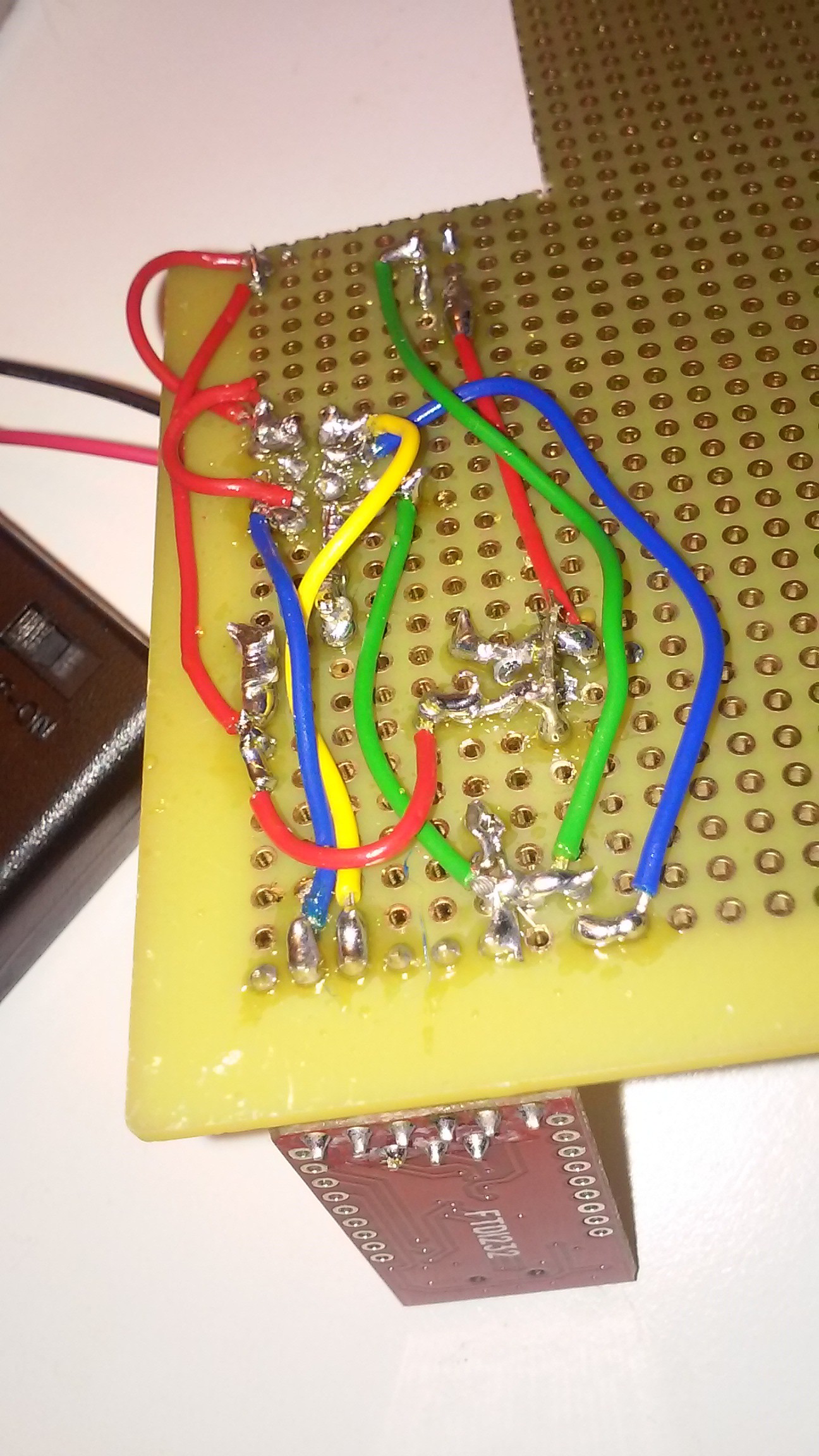
Still the board was misbehaving quite a bit. I looked into this issue and found that breadboards are too inconsistent to reliably test these type of chips. That meant the next step was to move onto a soldered proto-board. I added a DC power jack to the board so I could power the system with a simple 12 v wall wart. I got all the components in place, but could not get the system to work. Turns out I had a solder bridge, that was not showing continuity on my meter, but was contacting occasionally when energized. Re-soldering the joints and re flashing the chip verified this suspicion after many, many failed flash attempts.
![]()
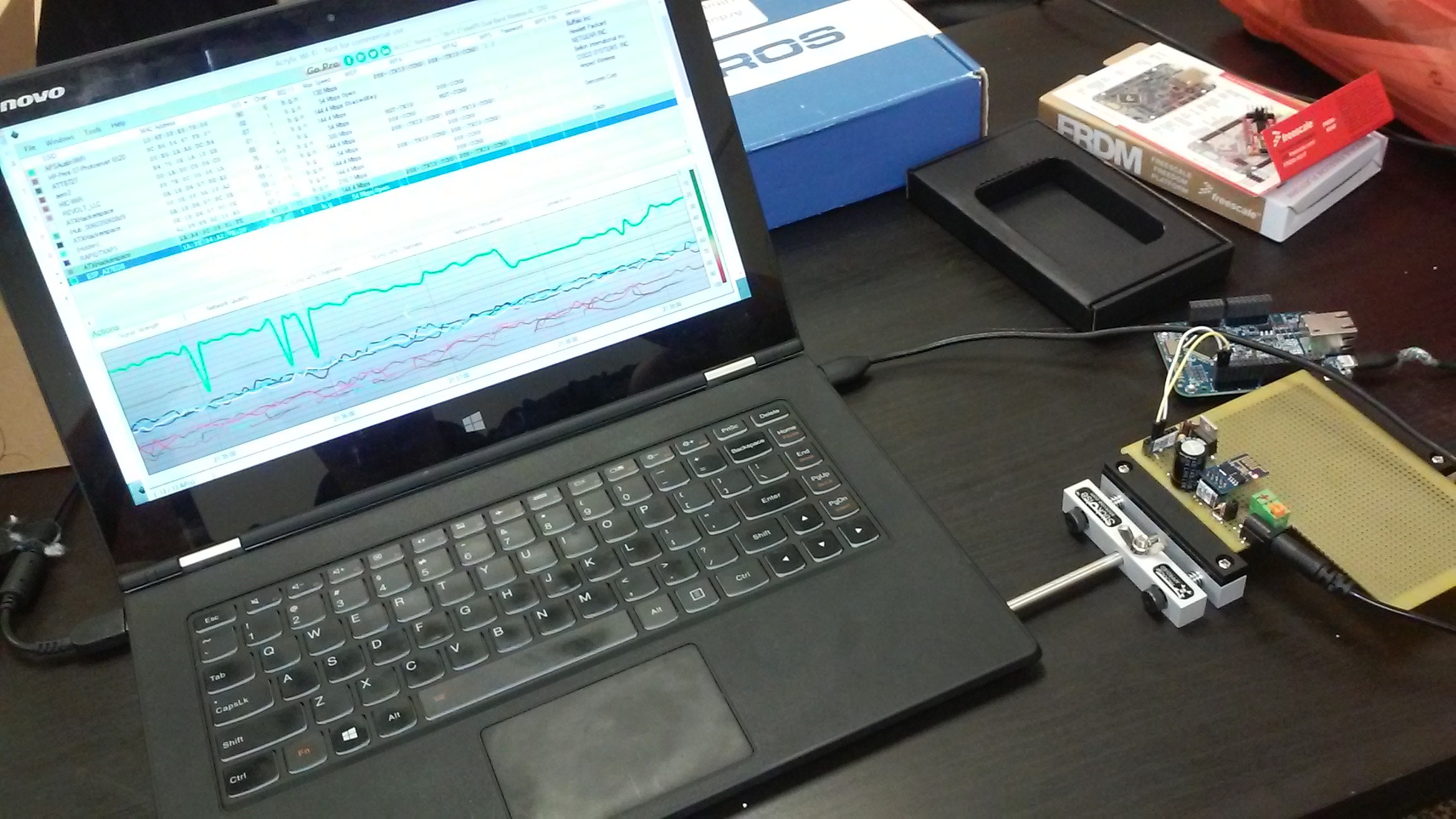
I wanted to analyze signal strength and consistency and found Acrylic WI_FI Free to be a pretty good tool to log this.
![]()
-
ESP8266 Fun
06/11/2015 at 19:29 • 0 commentsI have done quite a bit of work with my ESP8266 module, but have not gotten very far yet. For those interested in the fun of it I can fill you in obstacles I found. First off I was working with an mBed nucleo because I thought I could easy use that to emulate a FTDI chip. The Nucleo is 3.3 volt compatible and I would not have to drop the voltage like would be necessary with my easy to breadboard arduino uno. Well I after banging my head against the wall found out that the RX and TX serial pins that are labeled on the Nucleo pin out are not actually active on the board. Seems to be a mistake by STmicroelectronics on this one. Un daunted I started to use my FTDI232 module that finally came in from Amazon. Yea ready to flash my ESP8266... You guys remember FTDI gate? Yep, bricked device and bad drivers thanks to the software driver guys at FTDI. After a bit of research I was finally able to update my drivers and unbrick my device, but it took much longer than expected for my machine. So onward, ESP8266 device flashed with firmware! Now I have been bouncing back and forth between trying to use my FTDI232 and my mbed nucleo to test AT commands on the ESP8266. Some of the commands are taking, but now it appears I have a compatibility problems with my serial terminal that I have to track down to make my ESP8266 happy. I was able to get my ESP8266 working with a loaner Freescale freedom board in a IoT workshop, but it was only a loaner so I am stuck trying to get my equipment to work.
Stay tuned for my battery powered prototype of a ESP8266 transmitting data logged from a single sensor. I just need to get my serial terminal to cooperate. -
Example website for PASS
05/28/2015 at 22:34 • 0 commentsI am still in the early stages of development, but wanted to share an update. Here is a link to a sample website showing a map of a dream future state 6 months after product launch. The current air quality monitoring problem we have in Texas is that while the state's environmental agency has most large cities are covered, we really don't have a good picture of what is going in in large portions of the area. These open holes in the tracking grid leave us blind to what is going on in heavily populated industrial areas as well as effects from air coming in from the southern Mexican border. Getting this information would be very useful for spotting problems if they arise and help the community focus in on possible solutions. The map shown on the sample website illustrates how the community could work to fill in these data holes over time.
Next steps, I will work on getting my remote monitoring system prototyped with a ESP 8266 module and a Teensy-LC (Thanks HACKADAY!).
PASS: Pollution Analytics Shared Socially
A community pollution monitoring system aggregating pollution data from individual station users to get information on the environment.
 Joshua Young