Anthony
-
Inside
05/04/2015 at 22:46 • 0 commentsThe CL2909 is fairly easy to crack open once you know what you are dealing with.
Basic access can be performed via the following:
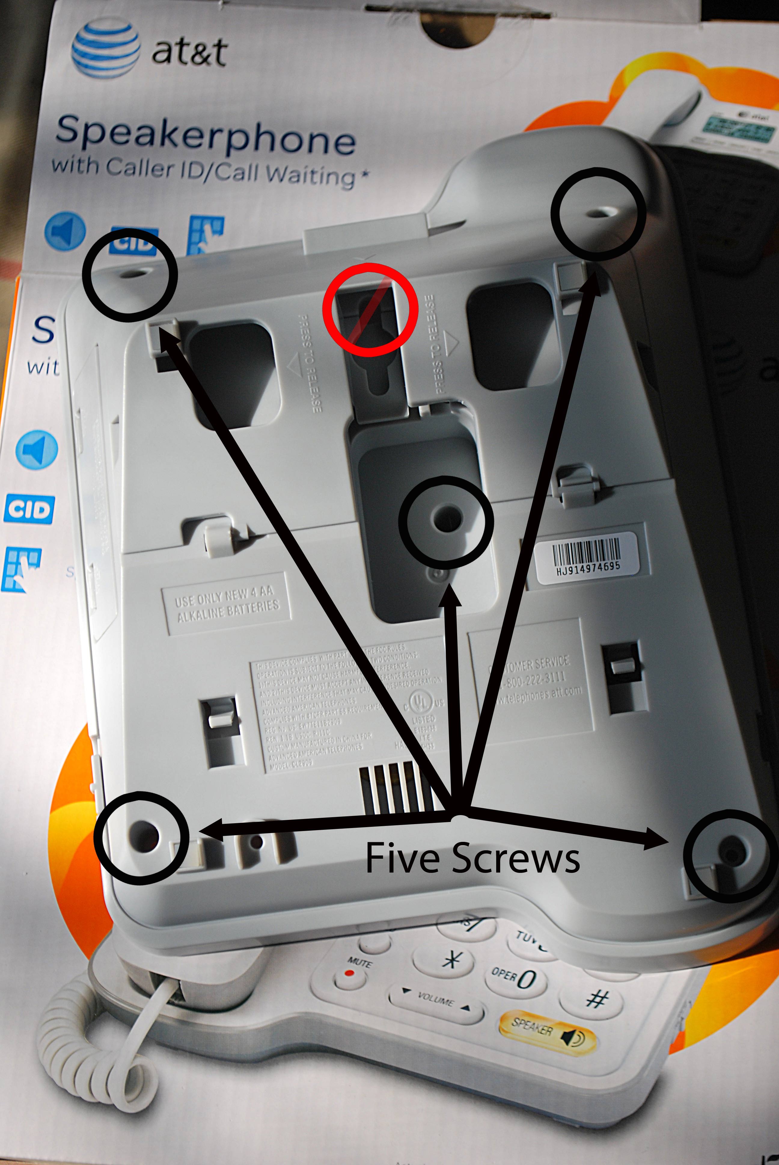
- Turn the phone over on it's front and remove the following five screws. The 'observant' or 'curious' will realize at this point the front 'sunk in' casing just 'almost' wants to pop out at this point but not quite, and thus will notice a deep sunk screw in the red 'verboten' area as marked. Just ignore this.
![]()
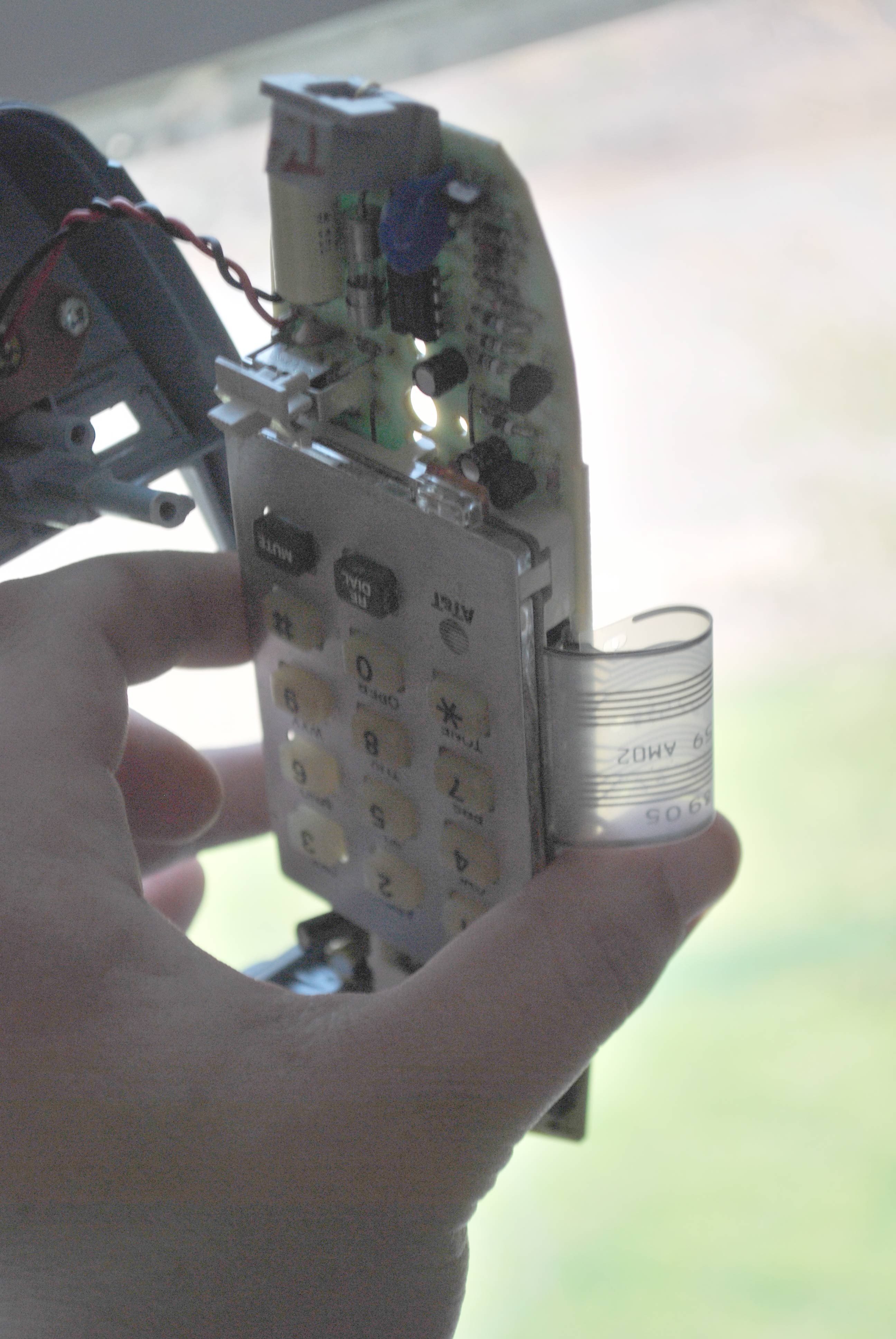
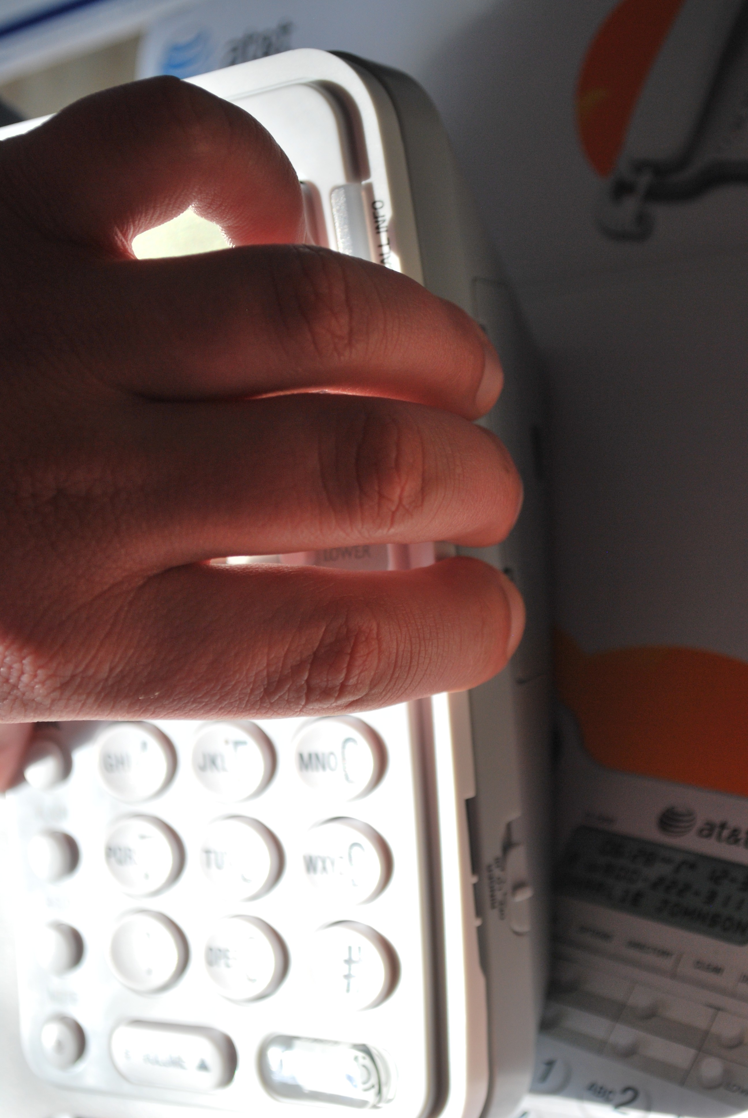
- Turn the phone back over, front-facing side and one will notice the right side front cover will lift, but the left will not. Gently leverage the right side with a flat screwdriver, etc.
![]()
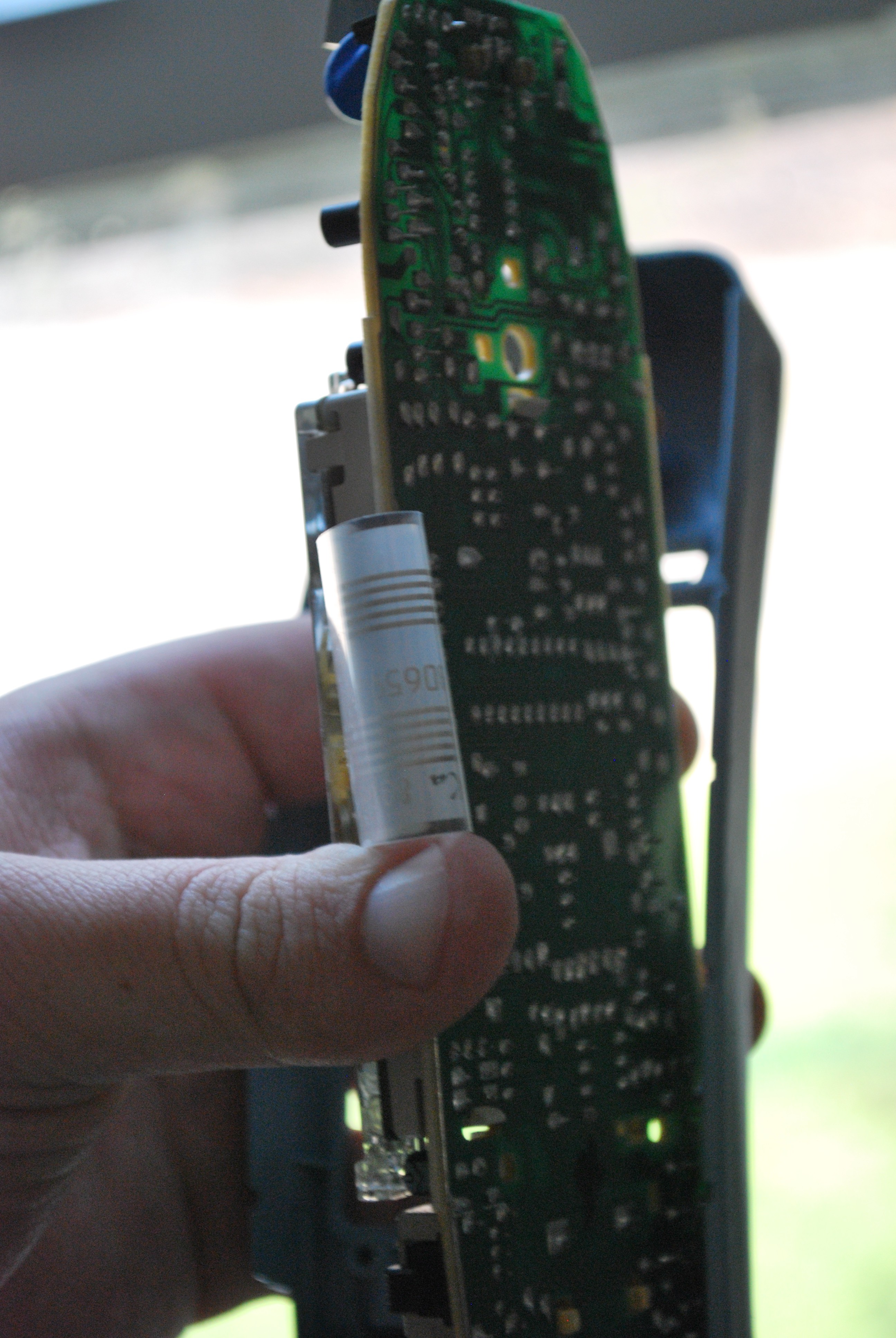
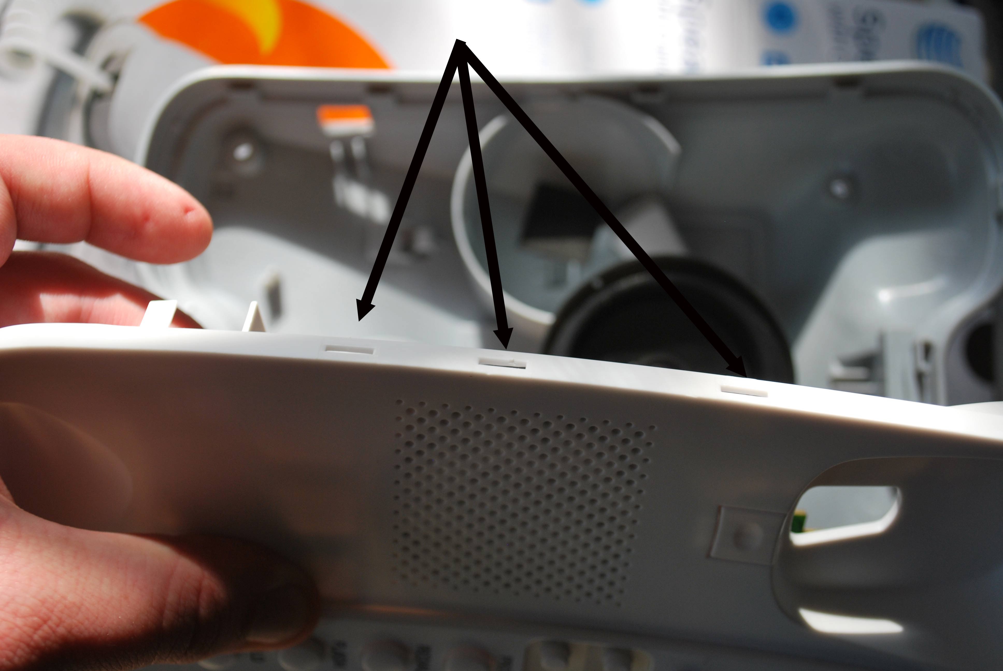
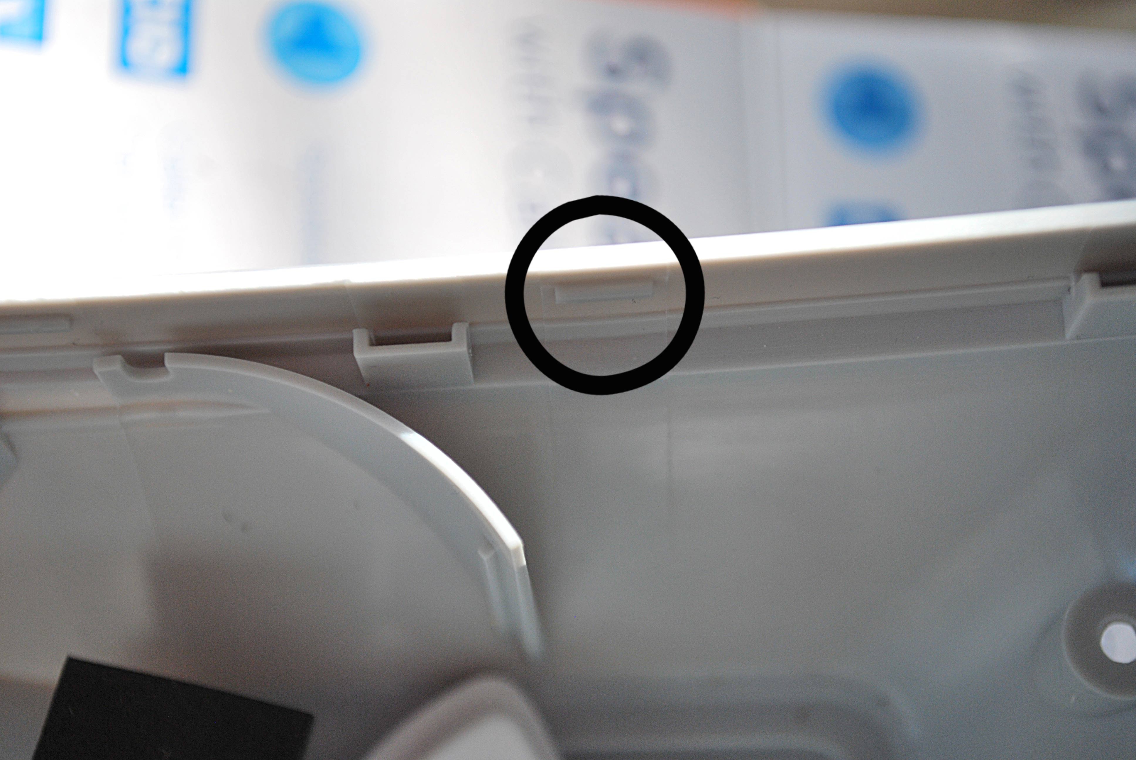
- I've tried to highlight the seconds that are impeding opening the device on the left side-- really just some very minor/slight tabs at three contact points. I've tried to highlight both. One could either approach this side with a second flat screw driver or just keep in mind that the cover must be lifted off gently from the right side to preserve reassembly. However one goes about it, in my experience it always helps going in to know where the stress/contact points are rather than having at it blind.
![]()
![]()
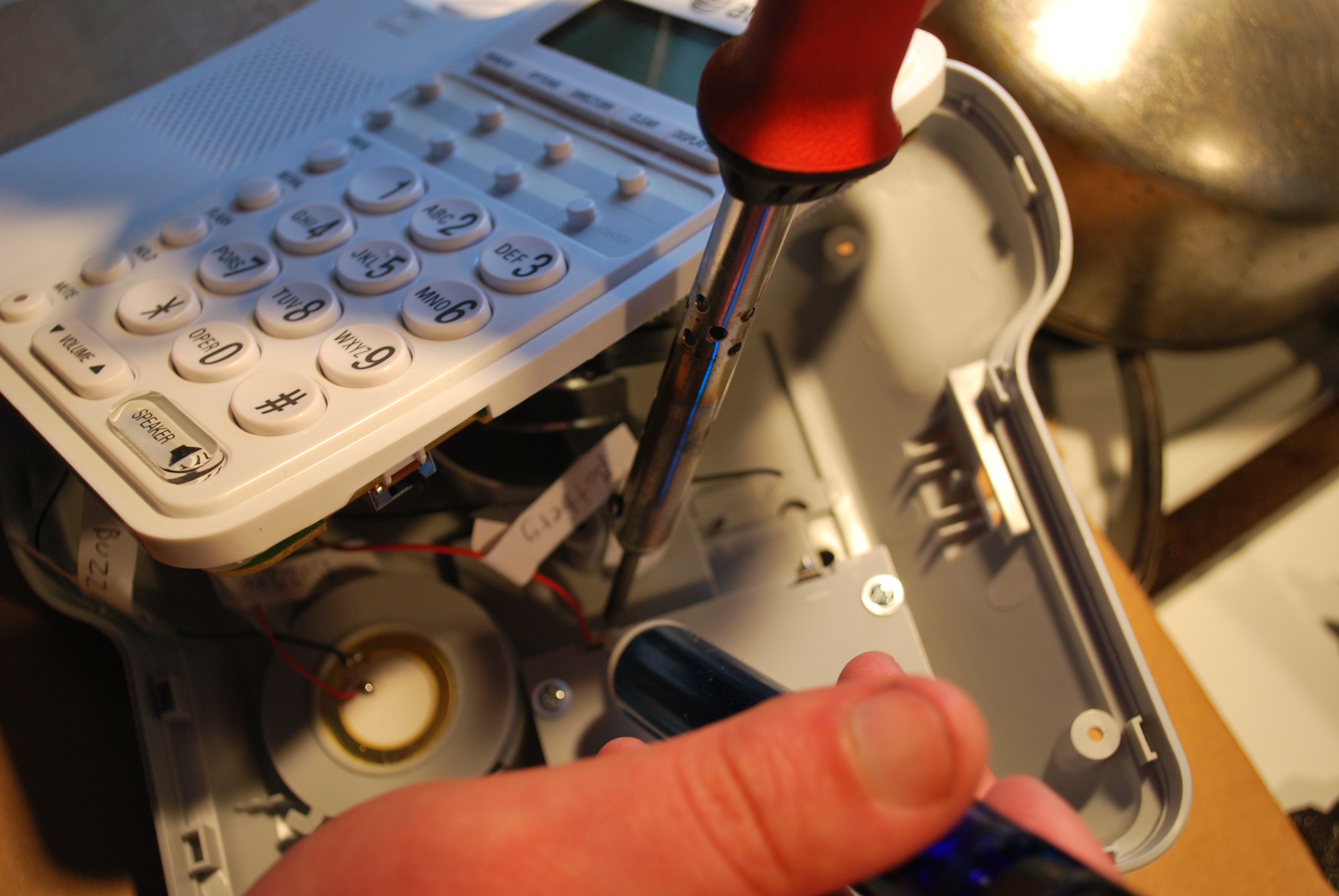
Once the device is opened, the next step is actually 'optional', but I find much easier to deal with (and as well as a couple of points not covered here, but should be obvious upon reaching this step-- That is, the handset rocker switch [which is encased], the 'Ringer' volume switch, and the handset jack itself on the side).
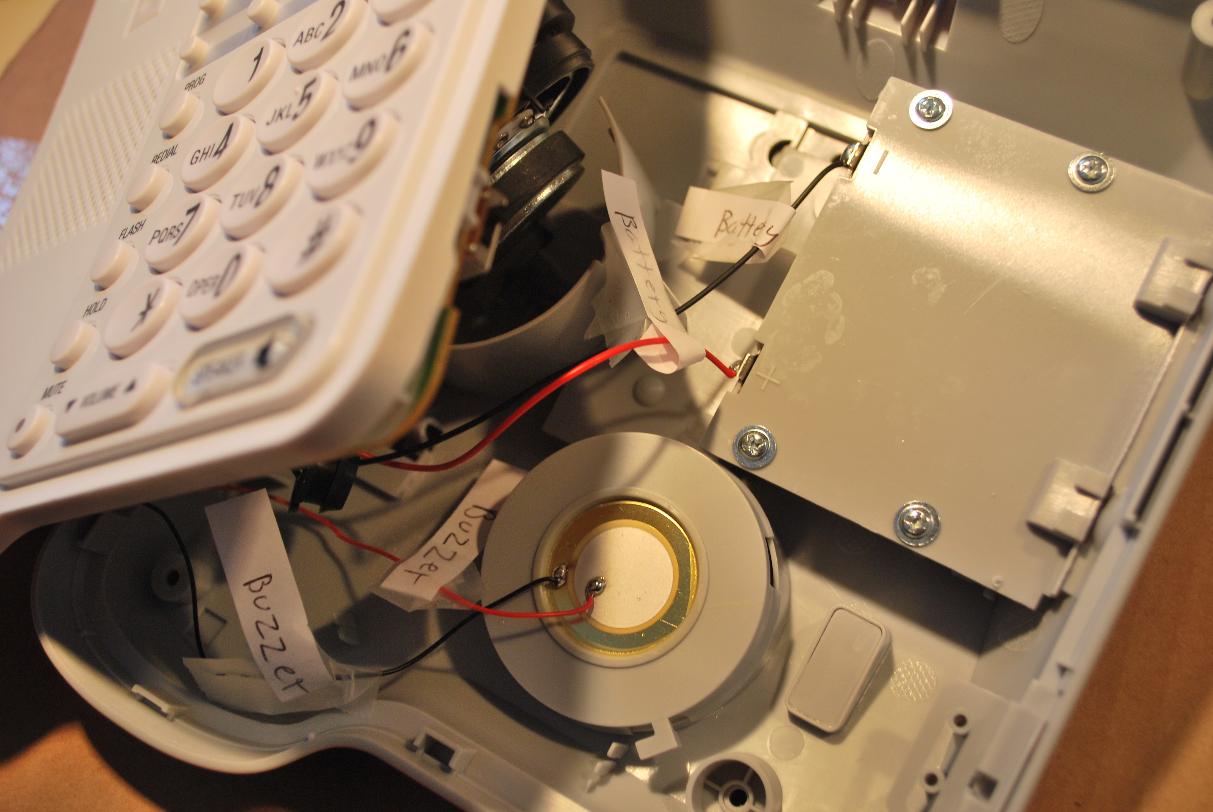
First one will find two (or three, depending) 'restraining' connection +/- wire pairs going to off-board elements. In this particular case, with this revision, the device is exceptionally 'good' about it as it is clearly stated on the silk screen which pair go to what (buzzer/battery), but always good to take the time to market/label them before removal.
The connections themselves could simply be cut and later re-spliced, but rather to make things a bit cleaner I decided to remove them with a solder sucker.![]()
![]() The 'third' element which I decided to leave in for testing purposes is the speaker, but this could also be similarly removed. At this point two sides should be able to be easily separated/detached.
The 'third' element which I decided to leave in for testing purposes is the speaker, but this could also be similarly removed. At this point two sides should be able to be easily separated/detached.Turning the front panel face down now we need to remove, again, five screws, which are pretty clearly referenced on the solder mask of the board but I have pointed out below for reference.
![]() At this point, it is interesting to note, from my originating statement the combination of SMT/SMD and through-hole devices used here.
At this point, it is interesting to note, from my originating statement the combination of SMT/SMD and through-hole devices used here. As mentioned, a similar late 70's/early 80's style device I first tried to work with:
![]()
![]()
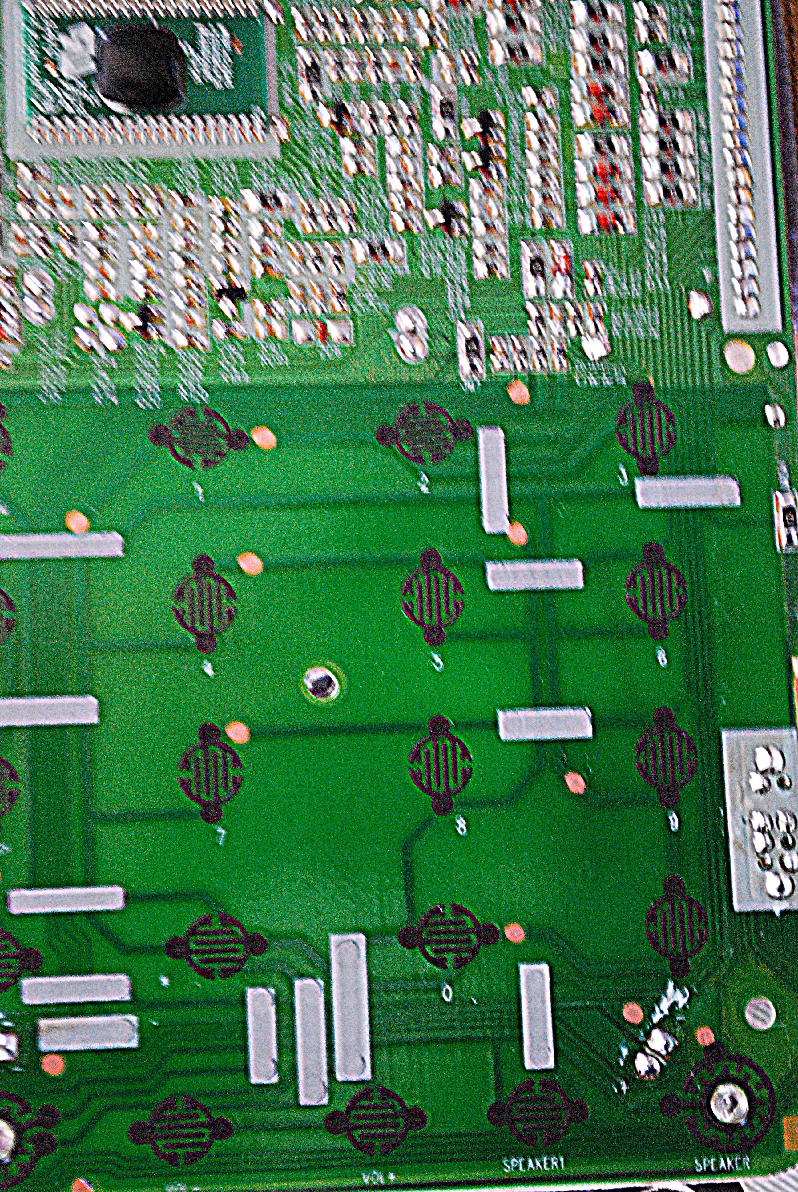
In contrast, here all 'appearances' suggest this is a really but a 'one layer' board but with very different technologies on either side... Above, side (A) (in brown), with 'through hole parts' [but notice no traces] and below, overturned, side (B), full of SMT/SMD parts.
![]()
I found this interesting as the combination between the two component types tends to be rather rare today, especially in 'hobbyist' devices, but the inspiration is on the order of shaving pennies of cost on several million devices. Or this board has only single side traces, which are much cheaper, and since there is 'extra space' in the case itself through hole caps and fuses are used on the reverse side of a single board layer layout.
More on the button layout and activation (for someone new to this at first one might ask, what is that ?! Captive touch ?! But it is just a traditional silicone rubber type, again frequently found in industry but perhaps less so in the hobbyist market.
Plus, then we will also properly reveal the traces (what the fiberglass pencil is all about-- and though I had heard of this before, let me tell you it is *amazing* at lifting solder mask without damaging traces. I am surprised it is not available at places like Digi-Key, etc, but should be a vital tool in your kit for hacking/PCB rework) once they are all proofed out.
- Turn the phone over on it's front and remove the following five screws. The 'observant' or 'curious' will realize at this point the front 'sunk in' casing just 'almost' wants to pop out at this point but not quite, and thus will notice a deep sunk screw in the red 'verboten' area as marked. Just ignore this.
-
Selecting/Prepping a phone
05/04/2015 at 00:57 • 0 commentsFirst item/order of business is finding an appropriate touch-tone phone.
At first this might at least appear an inconsequential matter, being seen both somewhat as a more 'obsolete' technology, and thus readily available, seemingly, at community recycling centers everywhere.
Further, with the Rasp Pi hardware alone we could consider directly 'generating' or performing playback of the dial-tones, and thus dispensing with the conventional base all together or establishing some other new or custom form factor.
However, for this build my requirements were that from the design perspective:
- The device remain 'seamless' or that is to say 'completely' familiar (i.e. the difference is on the inside).
- All 'conventional' functionality of the phone is preserved. Especially important if it is to be fully useful in an assistive technologies setting where, in the case of the need for emergency care (or device failure) [fire, call 911, etc] it still readily performs in the expected way.
- Out of the box I was looking for a 'corded' solution, a wireless handset is obviously a rather needless increase in complexity. Most 'cordless' device modules already include 'audible' device location beacons, but even for those of is that can see at least alright, still sometimes it is still like 'where's the damn phone ?'
During my initial scouring of several recycling centers for a suitable device a few things became apparent. While especially in the last 10 years or so 'touch-tone' as opposed to rotary seems 'old technology' there certainly was a time when touch-tone devices represented 'the cream of the crop'.
First invented in 1887, it likely wasn't until April 22, 1963 that President Kennedy signaled the opening of that year's World's Fair in NYC via the oval office by keying in the year '1-9-6-3' that such devices truly signaled in popular consciousness the desirability of 'the future'.
Still, it wasn't until the very end of the 70's and into the mid 80's that touch tone devices commonly came to replace rotary in the middle class life style.
![]()
Why is this 'historical point' relevant to the 'modern modder' ?
Well, a couple of notable things to point out. While these phone designs such as the 'Western Electric' above now seem 'retro-cool', they also represented at least a certain level of 'cutting edge' fab technologies.
Easy to forget, but important to recall, this was the era before SMT/SMD (surface mount) devices were common or affordable options-- Wave soldering and low layer density boards for consumer devices were the norm.
Further, even today, in a fact that is perhaps less 'well known' (but makes sense if you think about it for a moment), with the exception of the latest VOIP devices, or for anyone of some age that has ever experienced a 'black out' as a child and had a 'land line phone'-- When did you ever have to 'plug it in' ? Or just how was it at times the 'phone worked' even when the power was out ?!
In comes 'Tip and Ring', a sustained standard in all un-modernized systems since at least switchboard times. Thus when the phone is 'on the hook' or 'idle on the line' a nominal ~48V is being supplied.
When a call is 'rung in' to the customer, that value generally increases 90 V @ 20 Hz.
For the true 'Hackaday' user, there are even guides on how to 'tap a line' for power in emergency (emphasis on emergency, as it is of questionable legality) situations.
---
Aside from the history lesson, the relevance for this project is two fold:
- Any touch tone say, pre-early/mid 90's (?) era is already going to be 'stuffed'. Mod in 'other ways' but don't start off imaging your going to squeeze an XYZ package in there (and certainly not a RaspPi-- As mentioned, it already has 'too much' capability in many ways for what we need here, but is low cost, easy, accessible.
- Not all (maybe it was the 'Soviet era' I don't know ?), but many of these 'middle era' phones are not so much held together in their casing with easy to remove screws, but rather some form of adhesive. Whether it is to prevent easy 'tapping', or just the style of 'production' for the day, and of course not relevant to 'every model', many you will find kind of tend to want to break apart when you try to crack the case open.
Thus the selection of the AT&T CL2909 as my 'target device'. Full featured, held together with just a few screws on the back, and with a little thought, with ample space for whatever device. There are, however, a couple of small important points to be aware of so as to not 'break' the case, when opening it up, which I will highlight in my next post.
Voice Recognition Touch-Tone Phone
An inexpensive, reasonable 'at home' solution for the visually compromised.
 The 'third' element which I decided to leave in for testing purposes is the speaker, but this could also be similarly removed. At this point two sides should be able to be easily separated/detached.
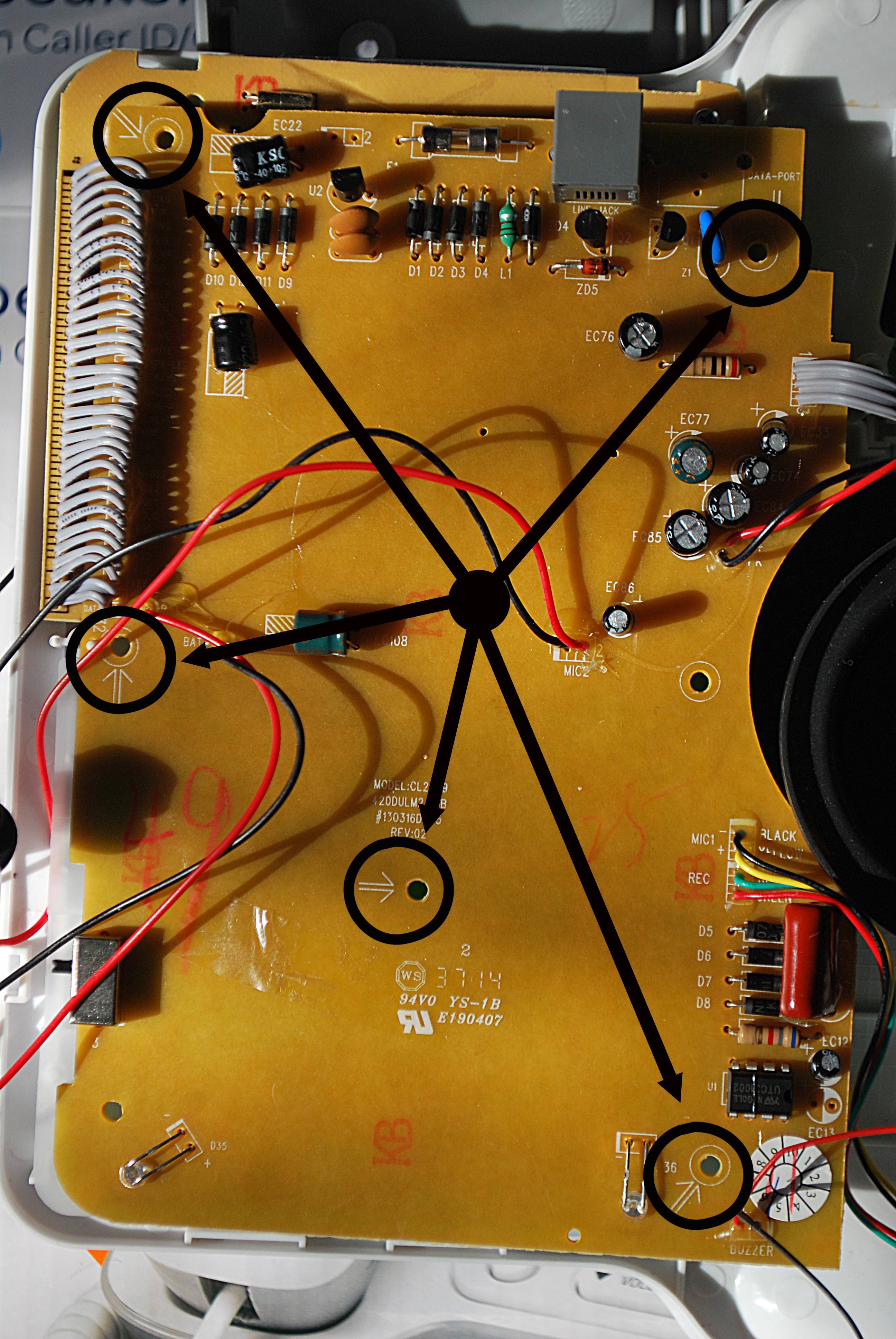 At this point, it is interesting to note, from my originating statement the combination of SMT/SMD and through-hole devices used here.