 SCART VADER
-
1Compiling the firmware
This step is not required unless you want to modify the source code. From a terminal/command line go to the folder/directory containing the source code and execute the following:
make clean
make
This will generate a
.hexfile containing the compiled firmware. After connecting the teensy board you can program it as shown in the next section or, if you have installed the command line version of the teensy loader application, program it directly by executing this:make program
You will be requested to push the button of the teensy board. Do so and the firmware will be downloaded.
-
2Programming the Teensy++ 2.0 board
You can find a detailed description of the following steps at https://www.pj rc.com/teensy/loader.html.
- Connect the teensy board to your computer.
- Execute the teensy loader application.
- Push the button of the teensy board.
- From the File name, choose "Open HEX File" and open the .hex file containing the firmware to be programmed.
- Select "Program" from the "Operations" menu, or click the Program button on the tool bar. You should see the "Download Complete" message.
- Choose "Reboot" from the "Operations" menu, or click the Reboot button on the tool bar.
-
3Configuring the software
When connecting the system to your computer it will recognize a set of joysticks. No special drivers should be needed. However, if the system is going to be used with arcade emulation software you will need to configure the emulator properly. First you will need to set the first four detected interfaces as the joysticks of the players 1, 2, 3 and 4. Also you will have to set the last button of each joystick as insert coin button. The fifth interface is used for interacting with the emulator and is not linked to any joystick by default (see the details section). You will have to configure its buttons for tasks such as pausing the emulation, resetting the emulated system,etc.
-
4Building the hardware
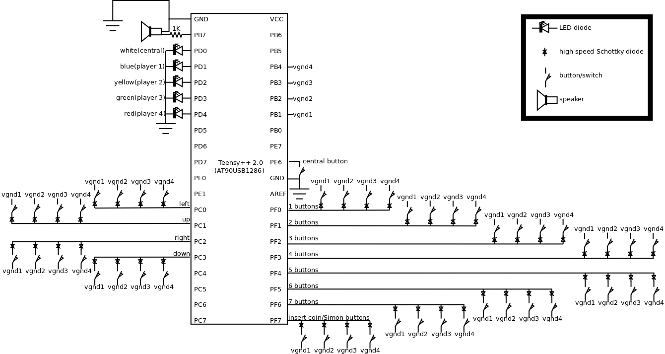
The components must be wired as shown in the following schematic:
![]()
The blue, yellow, green and red backlighted insert coin buttons must be connected to the lines vgnd1, vgnd2, vgnd3 and vgnd4 respectively. The white backlighted button is tagged as "central button" and has special functions. Note that, in my case, the lights of the backlighted buttons can be connected directly to a voltage of 5V like the one generated by the board. Other models may require additional series resistors in order to limit the current through the LEDs. In case of doubt look at its data sheet.
Arcade Joystick X4 Plus Simon Says Game
An USB joystick system with an integrated credit counter including a Simon says game to obtain credits and enable the insert coin buttons
Discussions
Become a Hackaday.io Member
Create an account to leave a comment. Already have an account? Log In.