Paul Kocyla
-
New kind of thruster in development
07/19/2017 at 20:34 • 1 commentJust a quick update after a long time:
The Dresden University will probably continue measurements on the BabyEMDrive thruster with an improved torsion scale. It can resolve 20nN.
Please check out another promising technology for propellantless propulsion. I decided to share the development and tests on a Mach Effect Thruster:
https://hackaday.io/project/26013-mach-effect-thruster-xperiments -
Tests
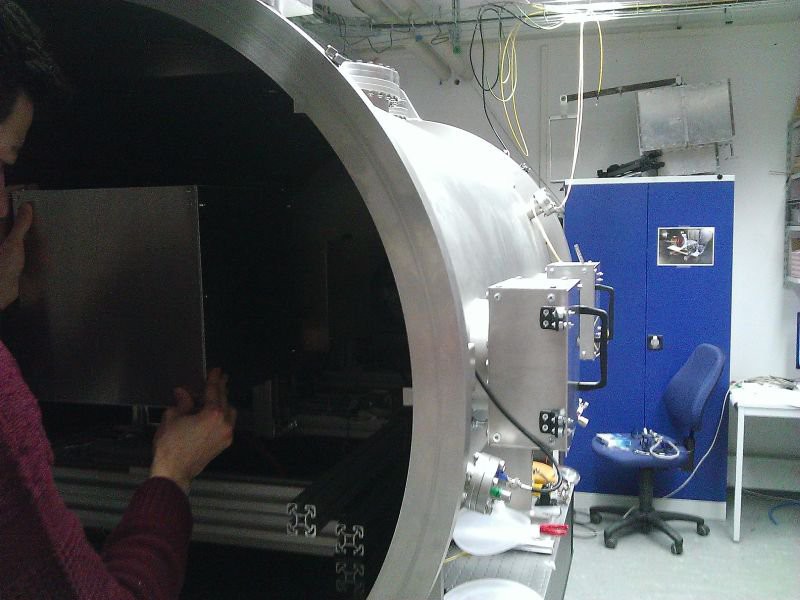
03/23/2017 at 21:20 • 1 commentIn February the EMDrive V6 has been under test on the Technical University Dresden.
![]()
As the pretest-board didn´t output the expected power, I made a quick redesign right before the test date.
The output after a day in vacuum was around 500mW, that´s "only" 3dB less than the desired 1000mW. Not so bad for a simple 4-Layer board.
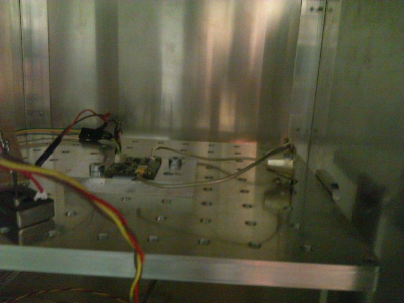
Here is the board inside the scale box:![]() I am not allowed to publish detailed results, but some information upfront:
I am not allowed to publish detailed results, but some information upfront:The thermal drift was much bigger than the possible thrust - anyway the force is depending on the frequency and seems - I say seems because that´ s only a quick observation - to be proportional to the amplitude of the resonance peaks.
I was only able to spend two days in Dresden so the following long duration tests has been made without my presence.
Possible forces are lower than 0.1µN, it´s still not 100% to say without eliminating the thermal drift, so we have to wait until this problem is solved.
The thermal drift shows always in the same direction and disturbs the interesting signal into uncertainty. So thrust is not confirmed but also not busted yet.
From my side - the Baby EMDrive is completed, unless an affordable amplifier with a significantly higher power appears.
There is an IAC abstract from Prof. Tajmar submitted about this EMDrive with details available on the conference beeing held in September this year in Australia.
Thanx to the many interesting discussions and suggestions.
Special thanx go to Prof. Tajmar, Matthias Koessling and Marcel Weikert for making the measurements possible, and Dave, who boosted the project by financial help - hope we get some thrust out of it so we can send it to space. -
Pre-Test smulations
02/05/2017 at 16:18 • 1 commentJamie (monomorphic) ran a simulation on the new EMDrive V5 cavity model. Great work and many thanx!
He detected two modes - would correspond with my two resonance peaks on the real thing.![Kein automatischer Alternativtext verfügbar.]()
![Kein automatischer Alternativtext verfügbar.]()
-
New board ready for testing
02/02/2017 at 22:42 • 3 commentsThe last board showed some power leak. The expected power could not be reached. It even degraded to 40mW - bad. Now I made a new board with better connectors and more careful routing which is ready for testing in Dresden.
It is prepared for the highly sensitive scale and can deliver more than 200mW with 24GHz at 85°C (after cable- and connector lossed), so we should not get thermal issues this time. The ALU-Plate will be also fixed to the scale for better heat dissipation.The cavity is new (blogged about it before). It shows two clean resonance peaks at which we will test for thrust.
Sweeps will also be made in case there are some other phenomena which may occur beside the two resonance frequencies.
For an eventual integration into a satellite, the board can find and track the resonance peaks automatically.I´ll make a 360° video of the test preparation in Dresden (if allowed).
![]()
-
Measurement followup
01/06/2017 at 06:07 • 1 commentImprovement in cavity resonance after simplifying the feed antenna:
In the previous measurements I soldered a stub to the feed connector to reach lambda/4.
In this configuration, this stub is missing. The feed pin is shorter than lambda/4 and its angle is the angle of the cone wall.
There are only two peaks now, the first was also visible before, the second has a more narrow bandwidth and higher amplitude.Probably these peaks represent two different cavity excitement modes in this frequency range.
We will track both of them in the next test session.
![]()
-
Cavity V5 measurements
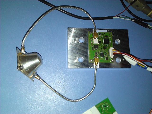
01/03/2017 at 21:19 • 5 commentsHere is the setup:
The EMDdrive V5 board is connected to the cavity´s feed antenna (lambda/4 stub).
A shorted antenna is used as feedback port which is connected to a power sensor.
![]()
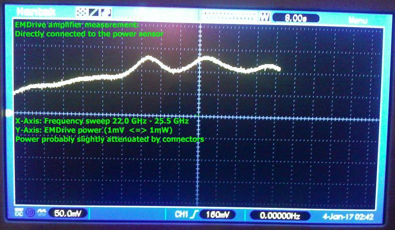
First, I measured the amplifier´s performance by connecting it directly to the power sensor.
Here are the results:![]()
At over 23.5 GHz the power is over 100mW - hmmmm it´s a 1000mW amplifier, so that´s not that good, the board is probably not perfectly designed, cables and connectors have losses. The sensor has a 20dB attenuator (compensated calculations for that) and a SMP to 2.92mm adapter, they will probably also cause some losses. So let´s say it´s around 150mW at the working frequency range.
Now comes the interesting part: The feedback port is connected to the sensor, and frequency sweeps are performed. It´s basically a scalar network analysis.
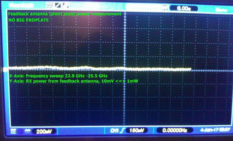
First, I left the cavity opened - this means the big endplate was not connected.
Here is the result - flat, almost no feedback. That´s not surprising, should be like this:![]()
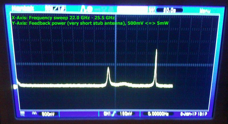
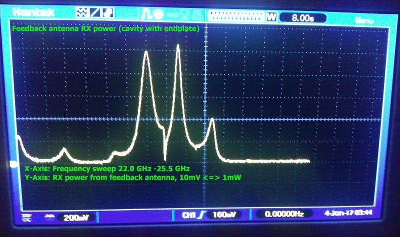
Look what happens when the big endplate is attached:
We get three main peaks. Two strong and one weak - and some smaller artefacts.
I assume the small disturbances are caused by the antennae destroying the optimal shape of the cavity.
![]()
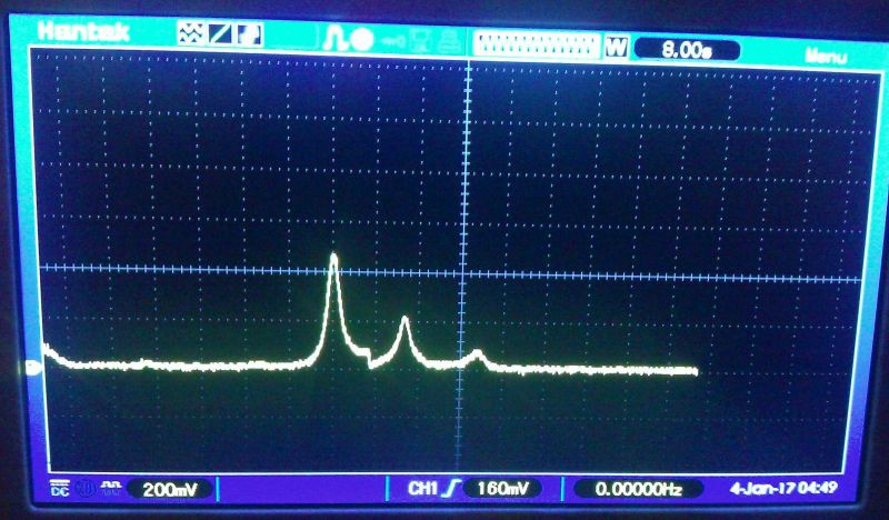
When you look at the power level, it seems that the feedback antenna is sucking all the power out off the cavity, not good, it was probably too long - but better starting off too long than too short. So I cut the feedback antenna shorter, from around 1.7 mm to 1mm (approximately). Here´s the result:
![]()
That´s better. The feedback antenna now sucks 40mW instead of 100mW. That´s better, but still too much.
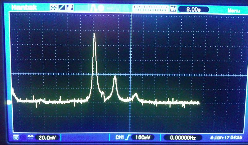
Now I cut the antenna to the ground, it´s just a pin in the hole, but the result seems ok:
![]()
Note that the V/div is now 20.0mV instead of 200mV, so it´s sucking just 10mW now.
Probably some room for improvement here - let´s see, but that´s acceptable.
BTW before the trolls cry again because of missing axis labels: The two last pictures have same labeling than the third last - I´m just too tired to insert them - have a newborn baby now and a full time job: X:FRQ sweep, Y: power 10mV <=> 1mW
-
EMDrive V5 and cavity prepared for testing
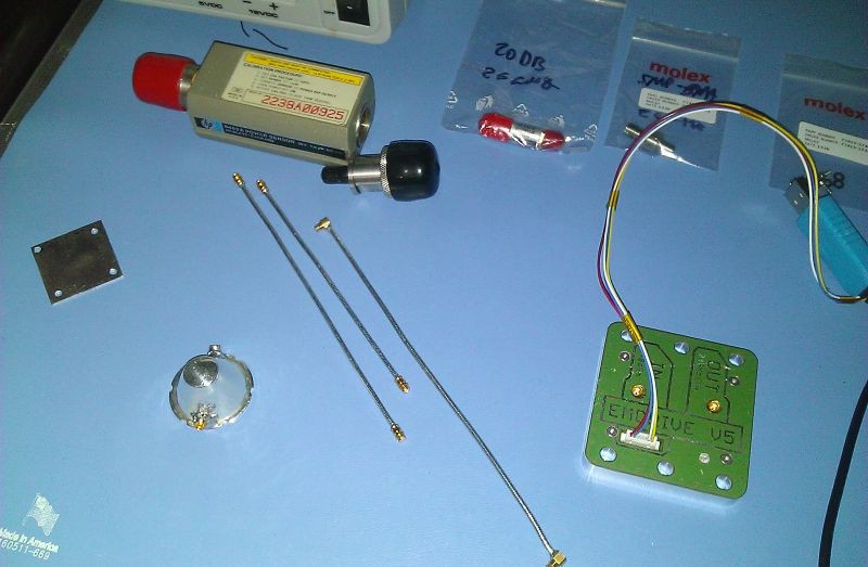
01/02/2017 at 20:48 • 0 commentsNew EMDrive cavity and board prepared for measurements.
A precise power sensor, cables (just assembled), adapters and attenuators are all rated for 26GHz.
I will be able to tell soon exactly how much power the amp is delivering and will be able to measure the cavity properties and resonance condition.
After these tests I will optimize the feed antenna for maximum power delivery. I will try dipole and loop.
The cavity has two ports: One with the feed antenna at lambda/4 distance to the big plate and another with a short stub for feedback.![]()
-
Equipment update
12/22/2016 at 08:52 • 0 comments![Kein automatischer Alternativtext verfügbar.]()
New member in the lab family: A precision power measurement device.
This device is capable of measung power qualitatively up to 26GHz.
The funny thing is that although the design comes from 1975, it´ s still in use today and it still has its price. It´s the only thing you can buy to achieve the measuring precision for these frequencies which doesn´t have the price of a new familiy car - 40 years later. At the time of release it was different.
Sensor head is the 8485a - was lucky to shot one on ebay for half the price they usually go.
But now finally we get exact measurements for the EMDrive, which will help to optimize the overall design.
The EMDrive itself will get its own power meter on board - in form of a small chip with less accuracy but good enough to do the job. But until then, this buddy will help to get qualitative results.The 26GHz equipment is quite expensive, for example a simple 2.92mm to SMP adapter costs over USD 70 - but it´s important to have the connectors and cables rated for the max. frequency, because in other cases the frequency response of the devices will have notches. Imperfections in the connectors lead to resonances and reflections inside the connectors, the connectors act like a weak cavity.
-
Cleaning up
12/17/2016 at 18:54 • 0 commentsThe "Flying an EMDrive" project has been removed due to maintenance overhead.
This doesn´t mean that the EMDrive will not fly - in fact we got a partnership which will make a launch available soon - stay tuned :)More details will come later - after we signed the contract
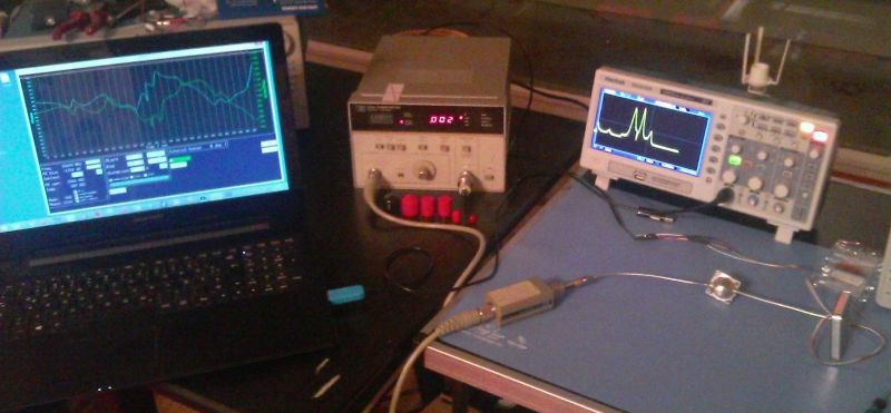
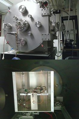
The things changed a little bit now. We had a test session at TU Dresden with Prof. Tajmar and will establish a lasting partnership.
The test results are not to be published yet due to an agreement, but what I can say is that the force was not high enough for a reasonable orbit test. The reasons were thermal issues in the high vacuum which caused the amplifier´s TX output power to degrade.
I made a newdesign with a more efficient amp in an externall box which can be thermally cupled to the scale.Here´s the setup:
![]()
I invested some of the funded money in a good used but affordable test equipment going up to 26GHz and will make a careful redesign for a next version V6.
The paperwork for the satellite launch has been initiated, there´s a lot to do in 2017.
I plan to do video blogging on the process. I am also expecting trolling as usual, so only constructive comments will be answered.
The project page will be cleaned up as many of the first steps to get to the current state are not helpful anymore (learning fails).
If you still need them then feel free to make a backup. -
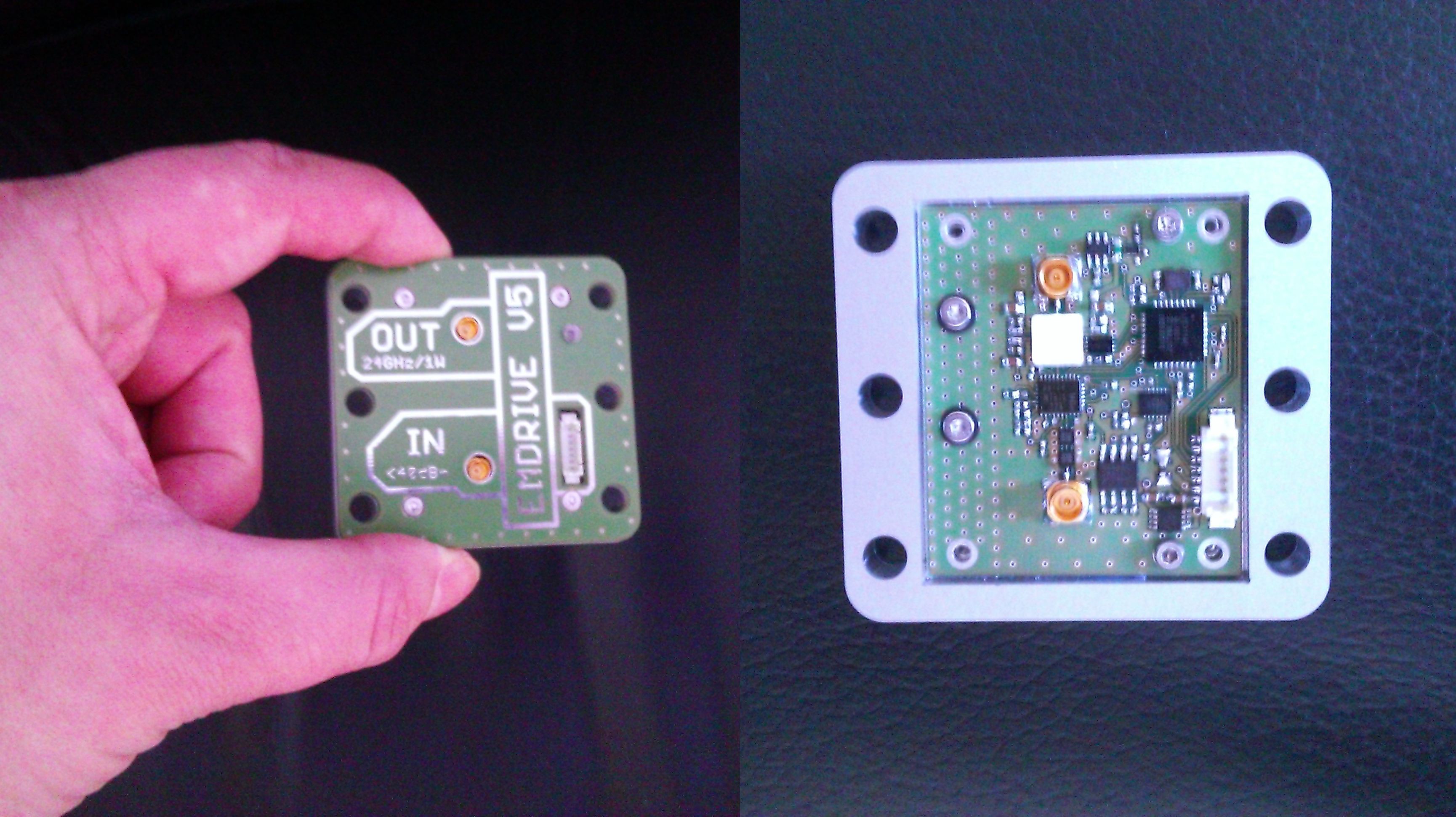
EMDrive V5
11/27/2016 at 20:55 • 3 commentsThe EMDrive V5 board is assembled.
The metal box can be attached to the scale body for better heat dissipation as we had heat issues during the testing in Dresden. There is also a more efficient amplifier on board which can delliver twice the power than the version V3.
Now waiting for the new silver cavity to come.![]()
 I am not allowed to publish detailed results, but some information upfront: