Paul Kocyla
-
Cavity Parameters
06/13/2015 at 19:06 • 1 commentMany people asked for detailed cavity data:
Height 24.37mm
Diameter 1: 29.64mm
Diameter 2: 16.12mm
Small dameter top edge to centre of injector: 5.60mm
-
Torsion Test (no data due to oscillations)
06/13/2015 at 12:47 • 9 commentsSecond test of our BabyEMdrive.
It was made in a small chamber, door locked to avoid airstreams.
The video is timelapsed so 1 second video is 1 minute in real.
We could not get useful data now, because oscillations still occur.
Reasons? Warm air from the LED lighting, some forces caused by the fuseboxes nearby?
Maybe we should try water damping (putting a piece of plastic below the setup which hangs into a bowel of water on the ground) -
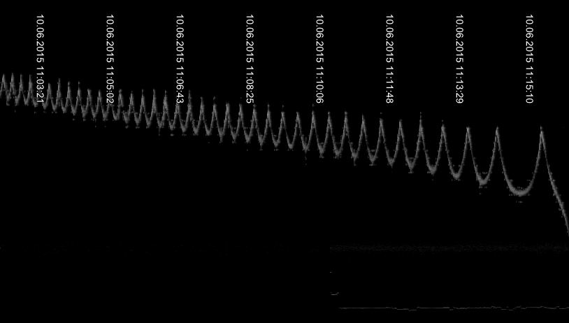
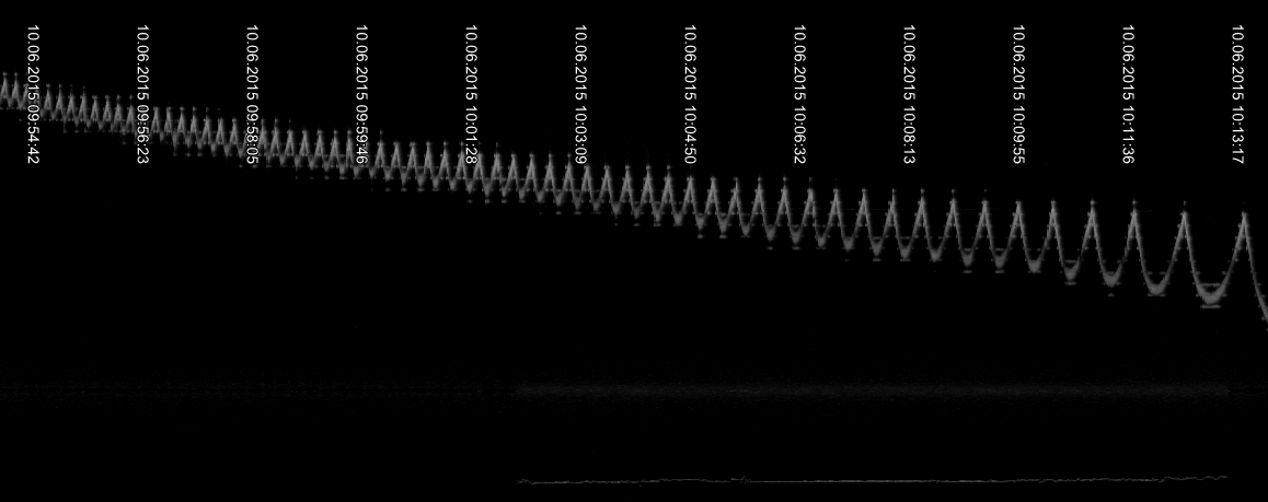
original recordings
06/11/2015 at 09:09 • 0 commentsHere are the original recordings of the first test.
The curve shows the rotation rate given by the gyro. What looks like a rectified sine is due to the imbalance of the platform performing an unsmooth rotation.
I measured the rate by the distance between these peaks.
Maybe it can be measured smoother just by following the overall deviation - but I was afraid that eventual radio frequency drift could mislead the measurement (recorded via SDR, rotation rate is directly transformed into frequency)
I´ll implement a digital protocol for the gyro data later, but this SDR technique is what I already had, so I used that.I´ll make another (smoother) graphs based on the overall deviation today (RF deviation seems not to be that problem)
First picture: retrograde, second: prograde, third: same prograde as second pic, but uncut graphics (longer unpowered time)
The thin line below indicates when the thruster was turned on (its the radio frequency of the remote switch)
Questions occured what prograde and retrograde exactly means in our setup:
Only the cavity orientation changed, other things of the setup remained unchanged.![]()
![]()
![]()
-
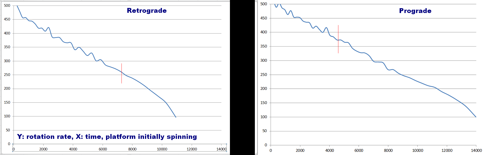
Possible thrust measured
06/10/2015 at 19:34 • 31 commentsEMdrive test results. Looks plausible - i think we have thrust :)
The platform was initially spun counterclockwise. After a whike (indicated by the red bar) the thruster was switched on.
Left: Thruster oriented retrograde (increasing rotation rate decay)
Right: Prograde (decreasing rotation rate decay)The data of higher rotation rates is a bit jumpy. The reason is that to get the rotation rate without much noise, i sample the duration between the peaks of the platform´s imbalance during rotation. The shorter they are the less precise the measurement - but the trend is clearly visible.
To get the proper time, devide X by 16.
Changing from retrograde to prograde was obtained just by turning the cavity around. Cables, batteries and other componets remained in the same place and orientation.
![]()
-
EMdrive tests
06/09/2015 at 20:05 • 6 commentsData is recorded and will be analyzed. We don´t know if there is thrust yet...
-
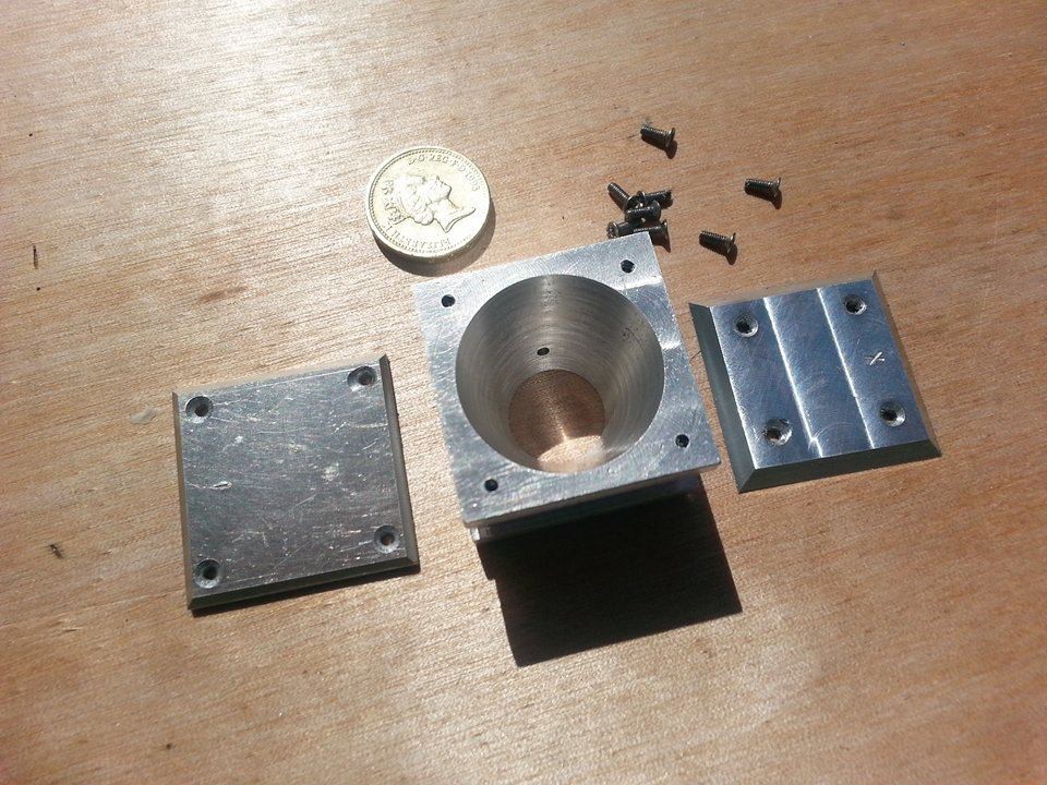
Cavity Finished
06/04/2015 at 10:53 • 5 commentsJo finished the cavity - we can perform the first test probably next week.
![]()
![]()
-
Jo finalizing the cavity
06/01/2015 at 19:45 • 0 commentsJo drilled the hole for the microwave injection antenna and will shave down some weight so our levitator will be able to lift the cavity.
![]()
-
Teststand BabyEMdrive ready
05/28/2015 at 16:11 • 2 commentsThe teststand is standing... eh... floating.
Left: Test platform and a radio remote control switch based on a 433 MHz OOK module. The chipstar board receives the remote signal to switch the EMdrive on or off.
It also sends the rotation rate of the platform.Middle: Teststand floating
Right: Rotation rate graph (platform slightly swinging like a pendulum due to imperfect center of gravity position, stabilizes within 30 minutes with cover over the system)
As soon as the cavity is ready, we´ll perform the test.
![]()
-
Floating test platform
05/27/2015 at 17:06 • 0 commentsFloating platform for our little EMdrive working (was one of these floating globes before). Capable of lifting 85 gramms, hopefully this will be enough, else I´ll have to modify the electronics of this thing.(We are aware of possible lorentz forces which may cause a rotation, we´ll take it into account)
![]()
-
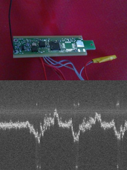
Thrust detection system
05/24/2015 at 19:35 • 0 commentsWorking on the thrust detection system for our EmDrive tests.
I´ll use our Chipstar board to send the slightest rotations by a radio signal.
For simplicity, I change the TX frequency according to the rotation rate, so it can be displayed and saved with an SDR-Software - in an analog oscilloscope manner.(The thruster will be a) hanging on a torsion thread and b) floating magnetically
![]()