-
Zero Crossing Detection
05/15/2015 at 08:18 • 1 commentMains power is comprised of an alternating current that flows in one direction and then in the other, along the cable, at the rate of 50 or 60 cycles per second.
The number of cycles in one second is called the frequency. The frequency is given in a unit called hertz (symbol Hz) where 1 Hz = 1 cycle per second .
The value 50 or 60Hz is dependent on the countries power system. The current alternates back and forth changing direction at the zero point.
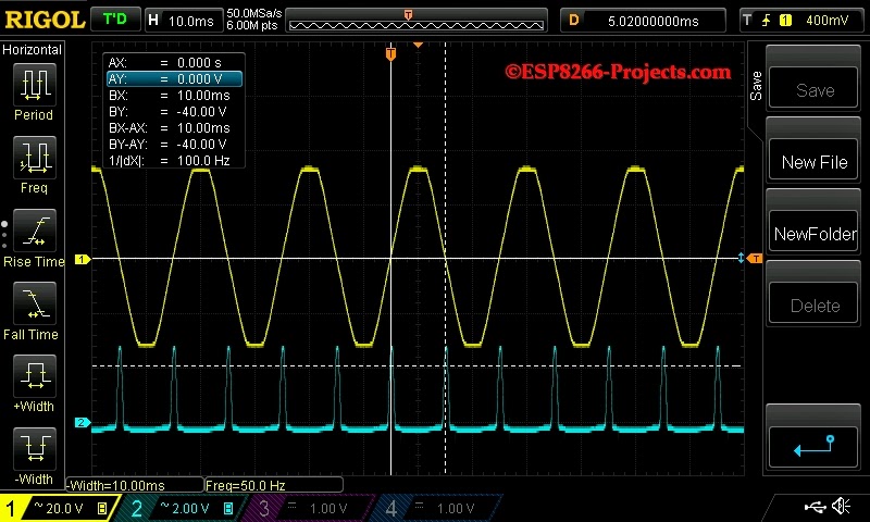
If we will to look at the waveform (yellow) with the Osciloscope it would appear as a sinusoidal shape. Drawing a line through the middle and this is what is called the zero crossing point. At this instant in time no current is flowing in either direction.
Yellow : AC line - 50Hz
Blue : ZCD module output
-
General considerations
05/15/2015 at 08:14 • 0 commentsThere are several types of dimmers generally available. These are used for resistive, and inductive loads, such as incandescent,cold cathode and low voltage (inductive) lamp sources. Note that not all electronic transformers used for low voltage lamps are suitable for dimming by Triac or Thyristors dimmers. In case of Thyristors you need 2 of them as Thyristor is a Unidirectional device and because AC power flows in both directions!
For resistive loads ON-OFF only jobs (no dimming required) a winning combination is between MOC304X for Triac driver (Zero voltage crossing one) and a good quality Triac, decently sized at the power needs.
In case of dimming you DON'T want to use a zero crossing voltage one! And this is because of the way the dimming process is going and depending on our own ZCD (zero cross detection) function. In our case zero cross detection is done by the biphase optocoupler as in the schematic below.
ESP8266 WIFI Mains Power Dimmer / Switch
Implementation of a ESP8266 based WIFI MAINS Power Dimmer / Switch Module
 Johnny
