 Tom Clement
-
1Step 1
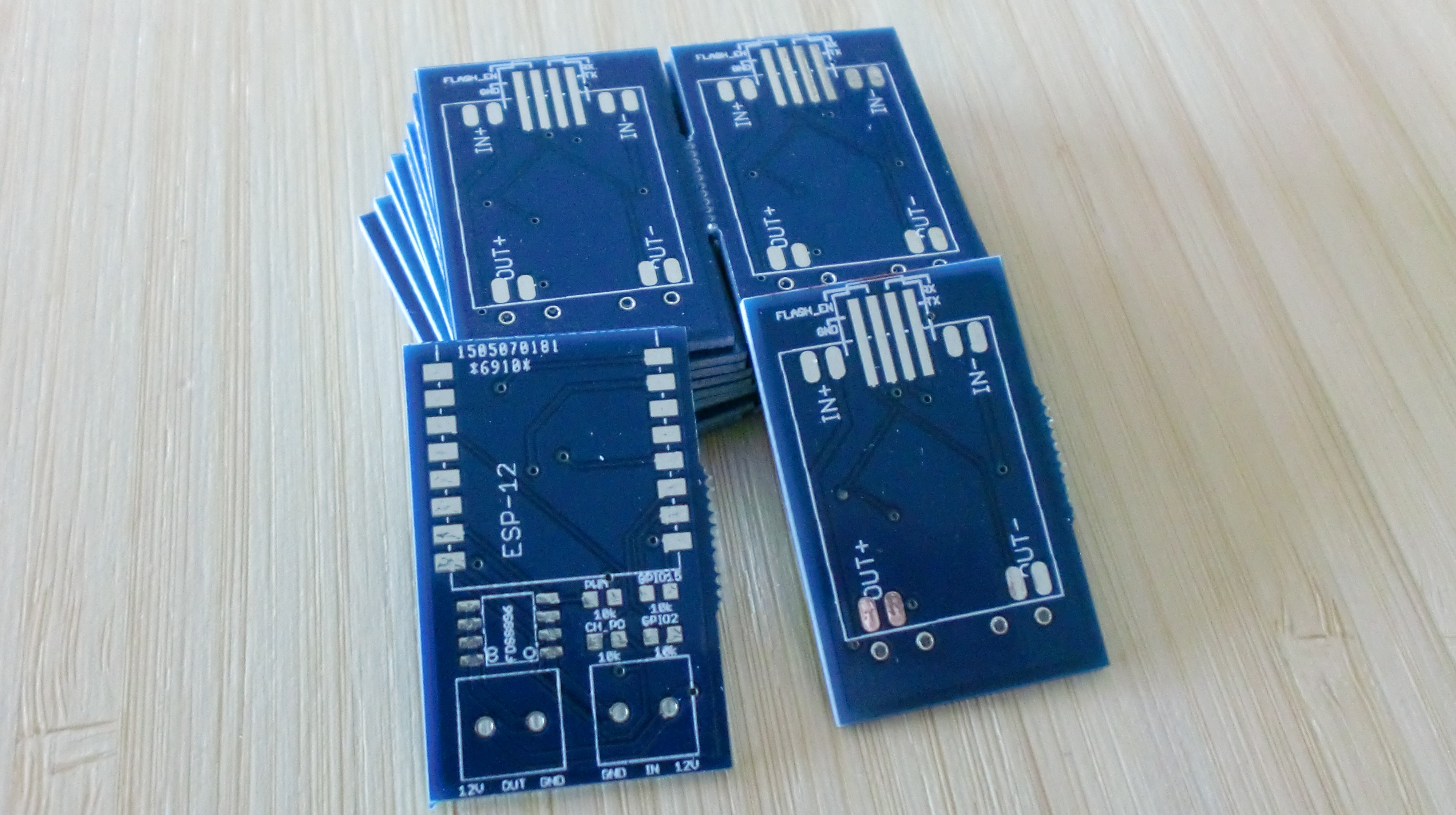
Assembling this baby should be easy enough for anyone who has hand soldered a couple of times before. First up is the PCB itself. It comes panellised into two modules per board, so break one in half.
![]()
-
2Step 2
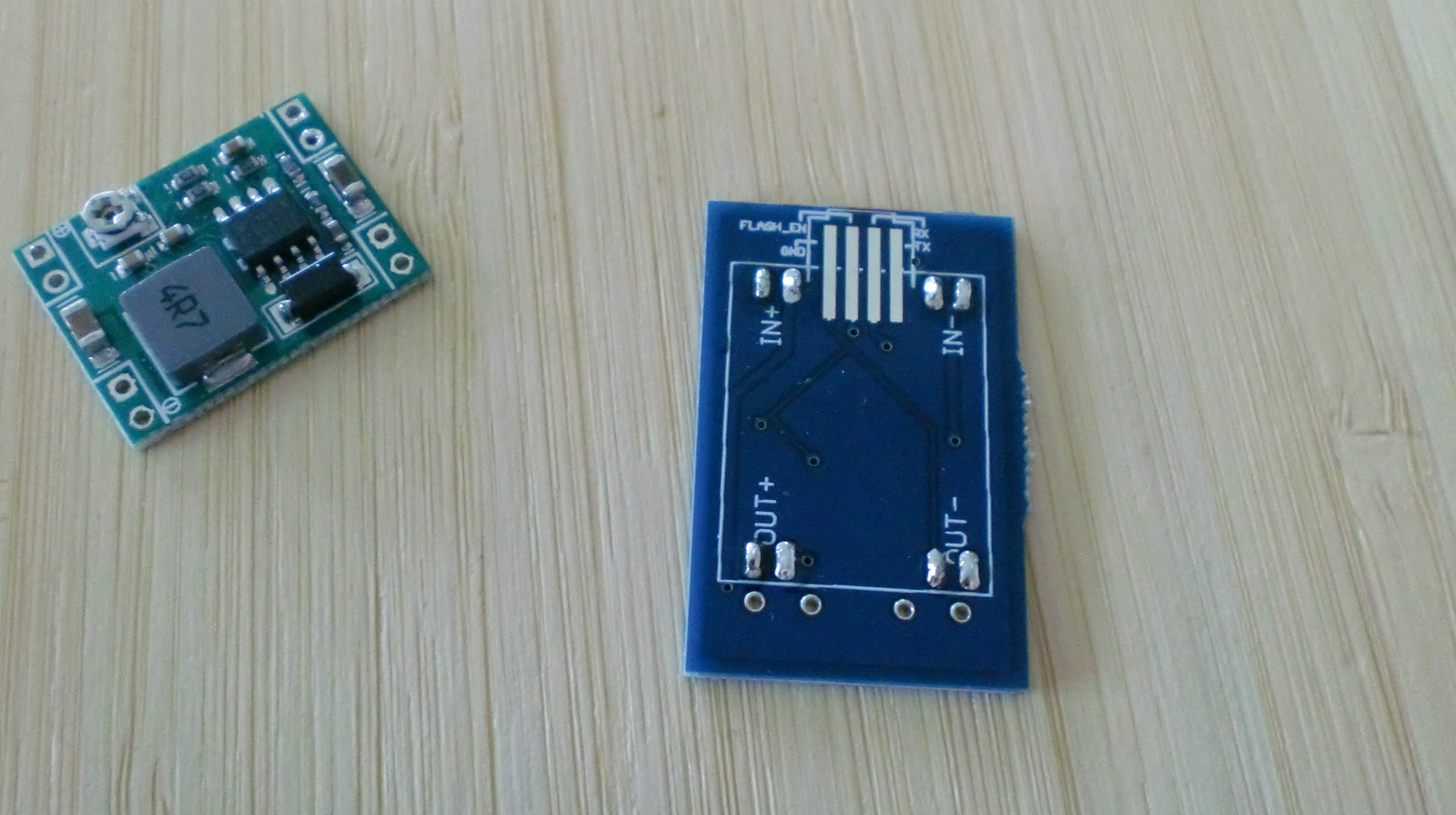
Next, we put the 12V -> 3.3V DC converter in place. I did this by first applying some solder on the 8 pads on the back. If you've not used solder flux paste before, try it. Seriously. Putting some flux on the pads before soldering makes your life a million times easier.
![]()
Then, I placed the converter on top (be sure to check its orientation! In this picture the part with the chip goes in the top). I then aligned it with the solder balls, heated up one of its pin holes, added a small amount of solder onto the pin hole, and let the solder seep through to the solder ball beneath it. Repeat this for all holes.
![]()
-
3Step 3
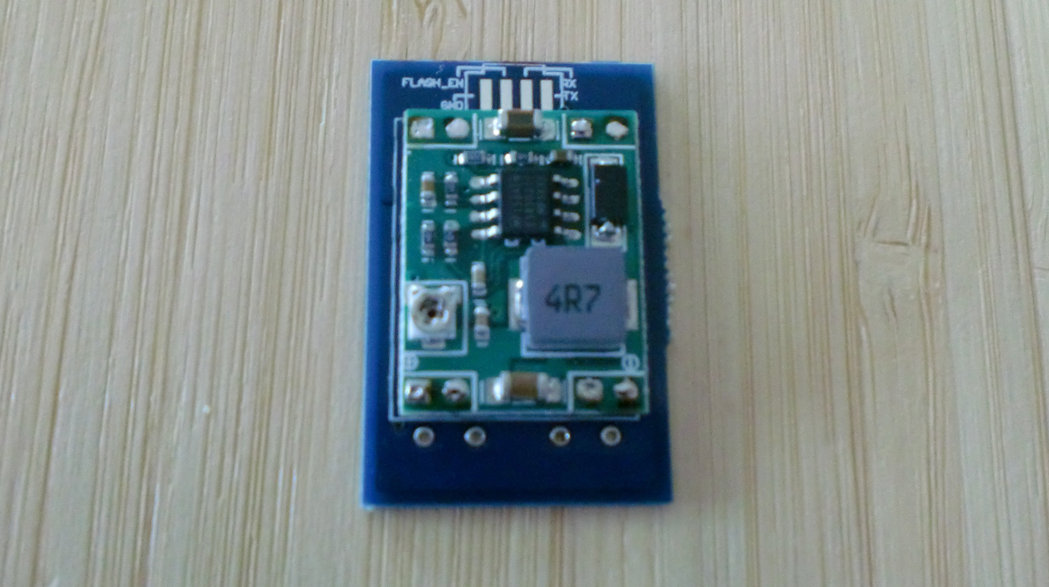
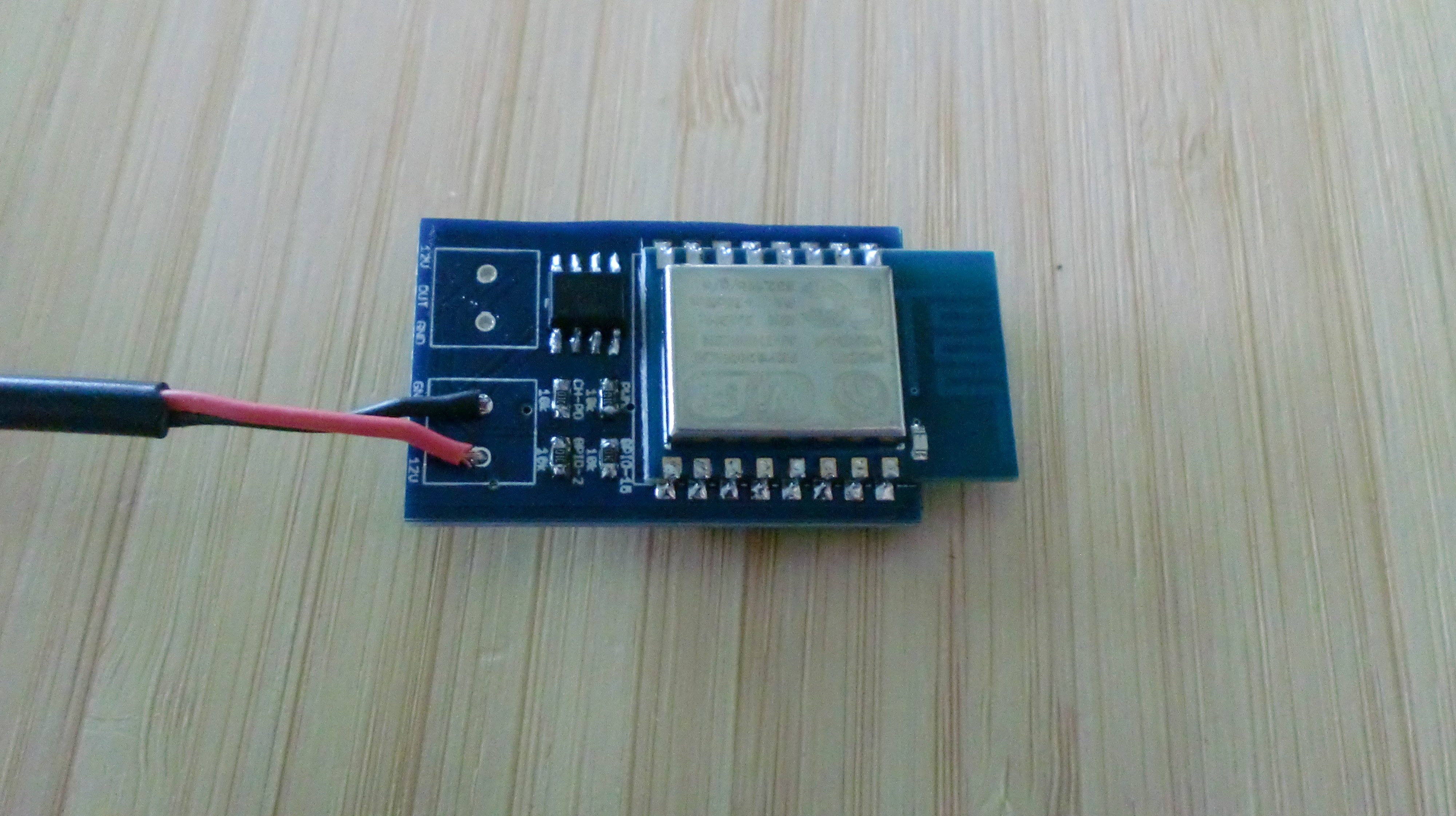
After that, I made sure that the converter was set to the right voltage. These converters are configured to pass on 12V by default, which would kill the ESP8266 chip immediately if found out too late.
The output voltage can be adjusted by turning the screw on the lower left side.
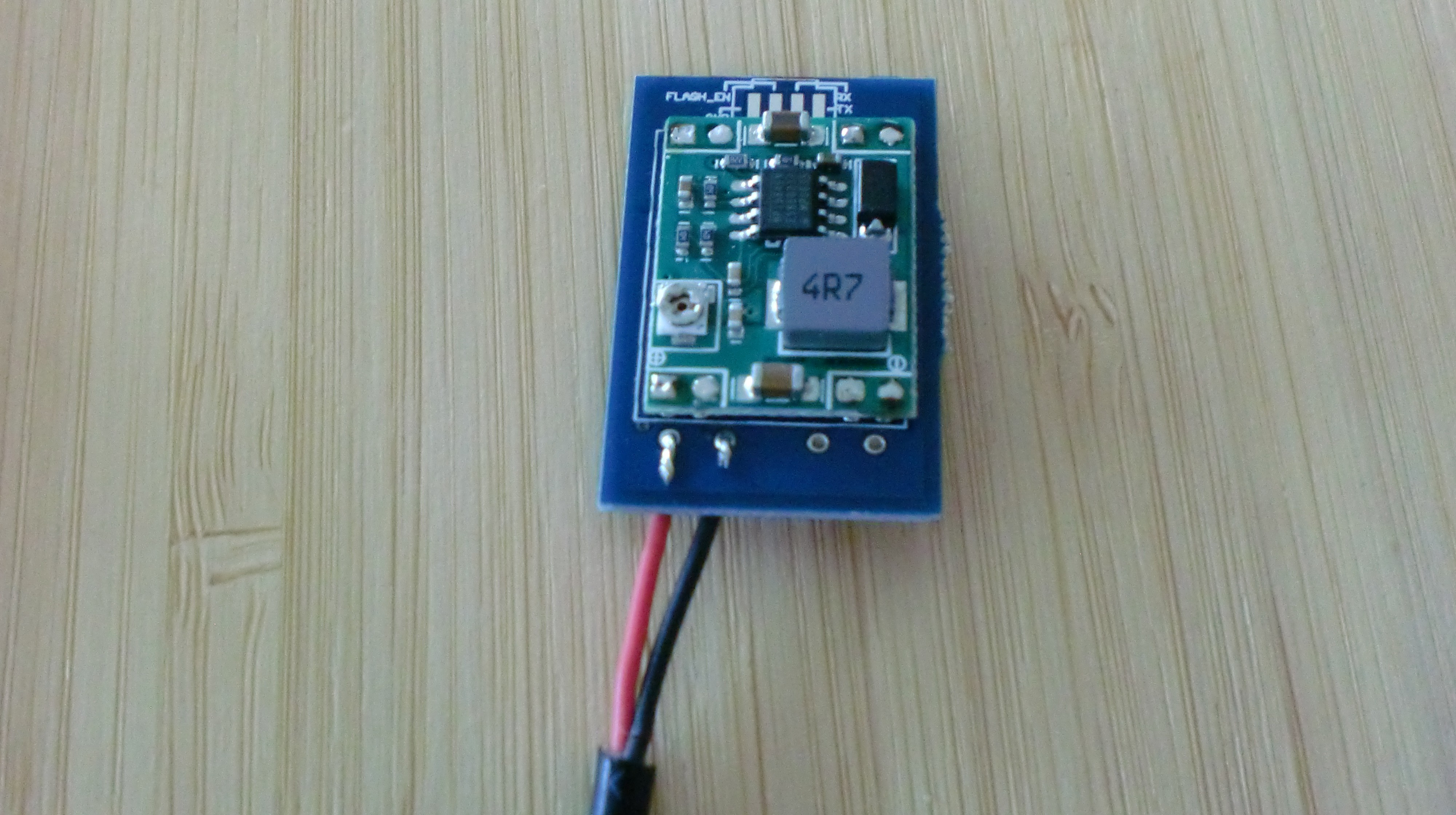
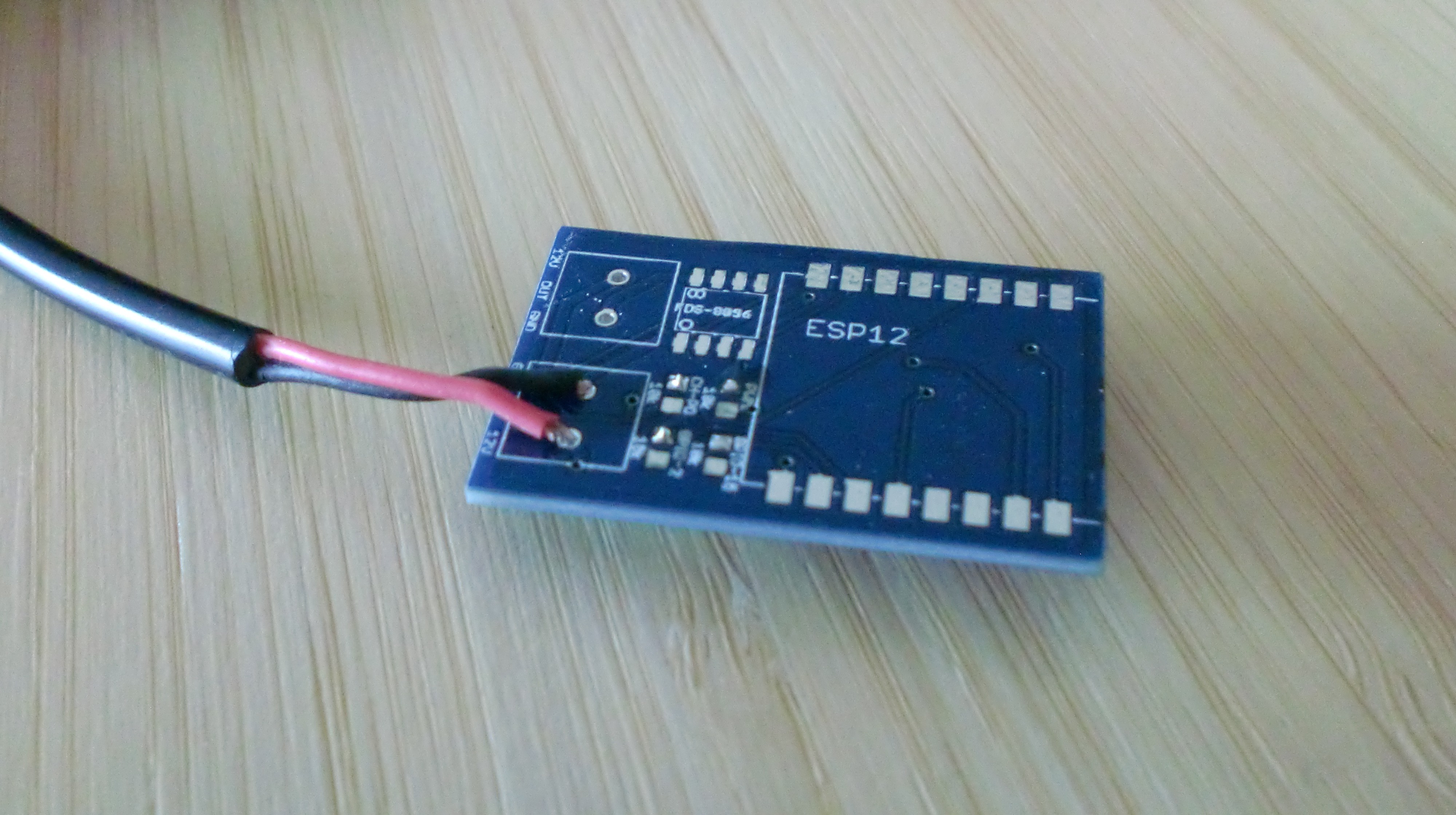
Because the screw terminal blocks hadn't arrived yet when I was putting this one together, I soldered the 12V power supply directly to the board:
![]()
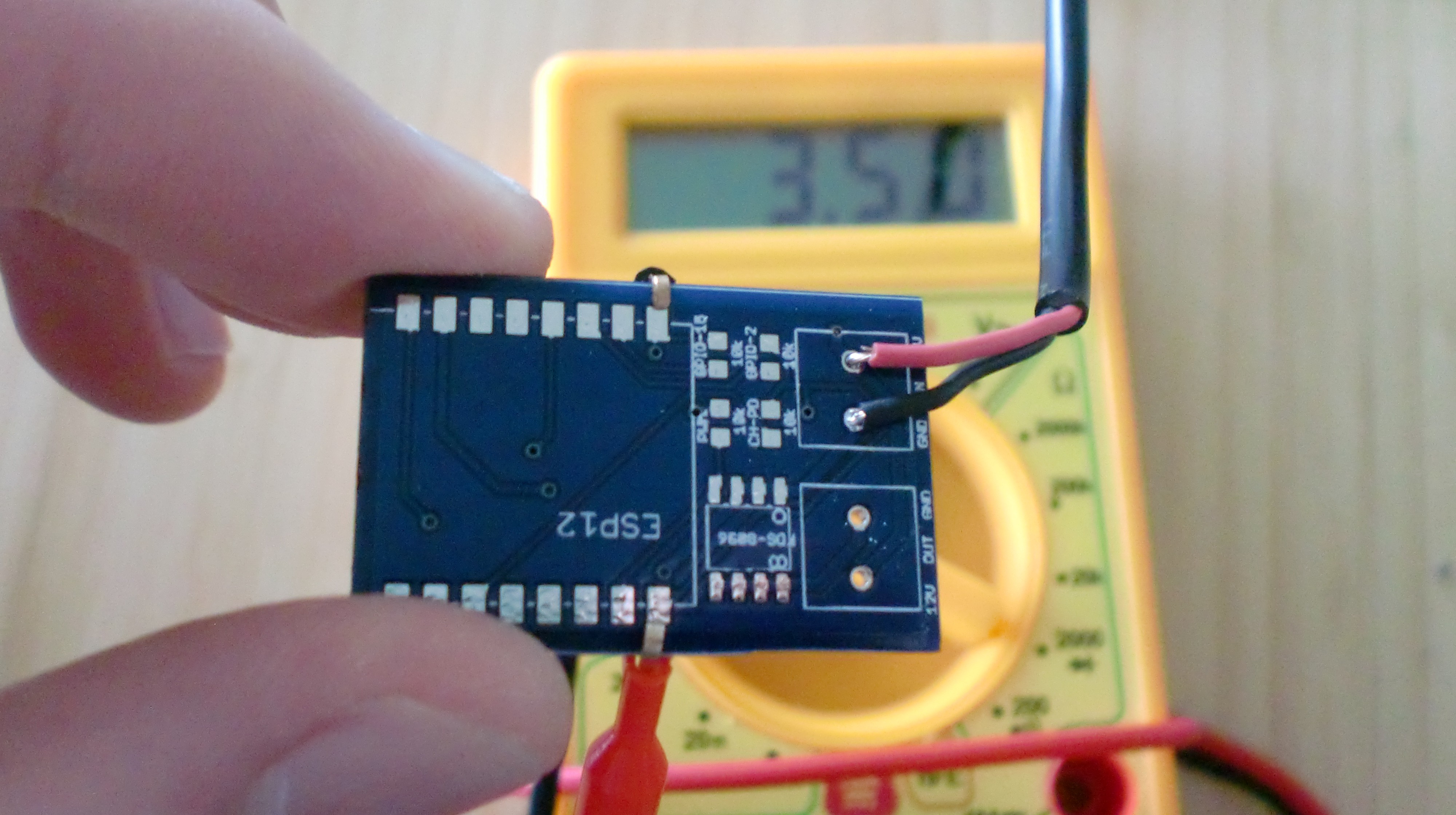
I plugged in the power supply, and measured the voltage across the ESP vcc and gnd pads. In order to reach the vcc pad, I sanded the part where the PCB was broken in half down a bit.
![]()
After setting the output voltage to roughly 3.3V (I tend to give it a bit more, 3.5 is still within the ESP's specs), unplug the power supply again to make sure you can't short anything during soldering.
-
4Step 4
We're getting somewhere! Soldering the 0603 resistors by hand looks daunting, but it really isn't that hard. You can find very nice instructions explaining how to do this here: A pair of tweezers is crucial, I don't see how you would do this without.
So, put some solder on one of the two pads for each resistor:
![]()
Then, grab a resistor using your tweezers, heat up one of the pads with solder on them, press the resistor into the solder, remove your soldering iron, wait, and let go with the tweezers one the solder has hardened. Do this for all four resistors.
Once that's done, apply solder to the other pad of each resistor, and you're done! Wasn't that easier than expected?
![]()
-
5Step 5
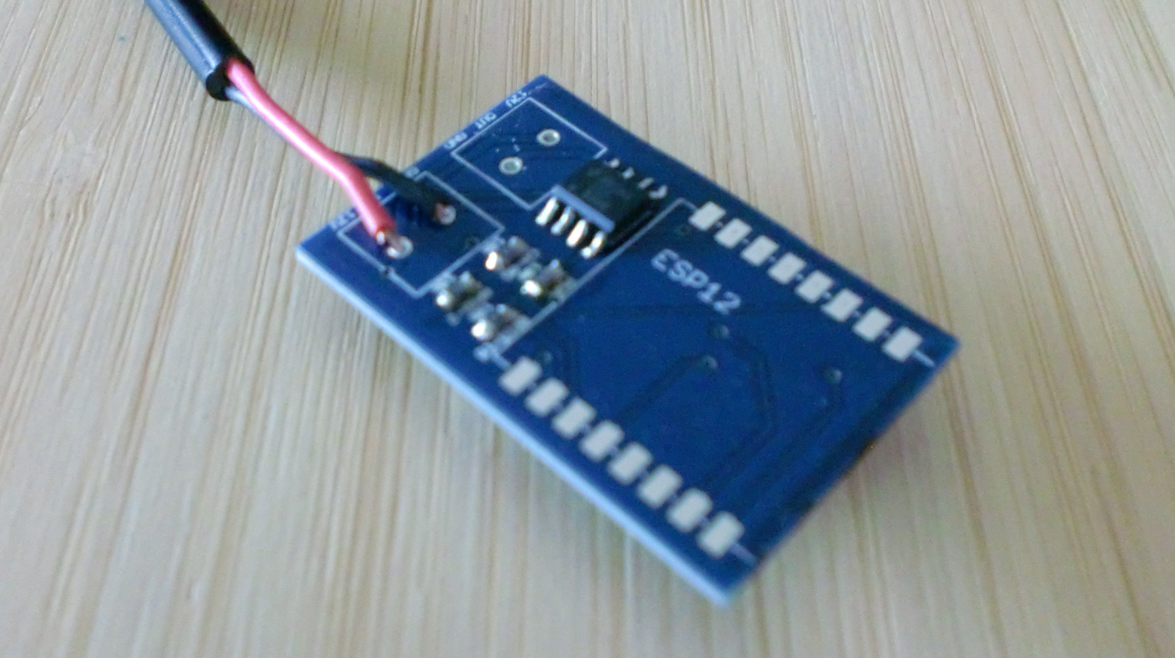
After the resistors, the switching transistor chip should be peanuts. I like to get it aligned perfectly first, then solder one corner, and then the diagonally opposite corner. This way it's locked in tight, and soldering the other pins are a lot easier.
![]()
-
6Step 6
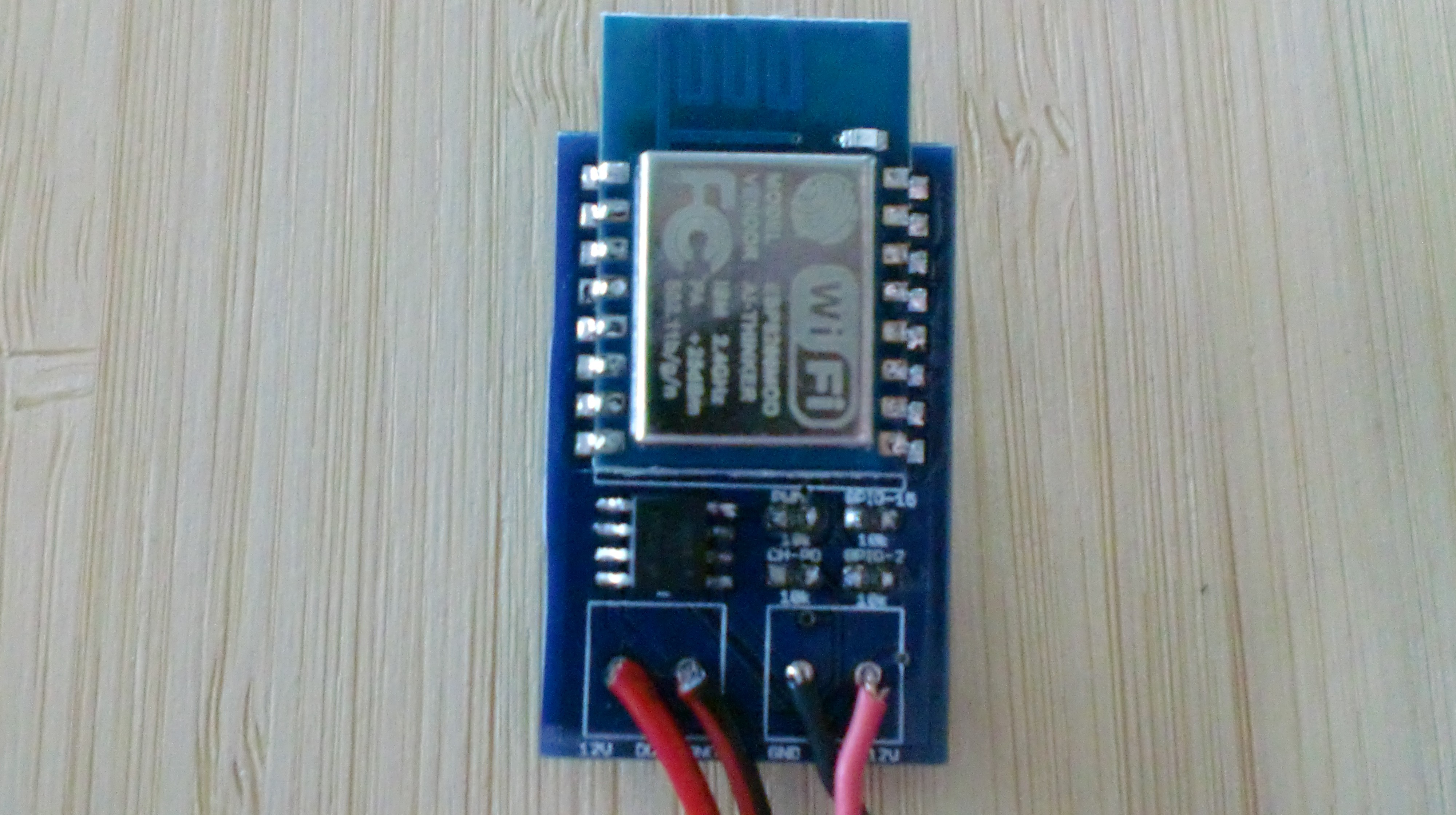
Next up is the ESP chip. I can't stress enough how important it is you set the correct output voltage in step 3! Don't blow up your components! :)
The ESP is super easy to solder, just follow the same diagonal strategy as you did on the transistor, and you'll be golden.
![]()
-
7Step 7
Finally, connect the LED strip to the OUT section. Keep in mind that the GND wires of the IN and OUT are next to each other, and the 12V wires are on the outside of the module.
![]()
A job well done, great!
$5 Wifi (RGB enabled) LED Dimmer w/ ESP8266
A super tiny LED dimmer, controllable from any device, based on the ESP8266. Doesn't require an arduino or rasp pi.
Discussions
Become a Hackaday.io Member
Create an account to leave a comment. Already have an account? Log In.