-
1Step 1
![]()
-
2Step 2
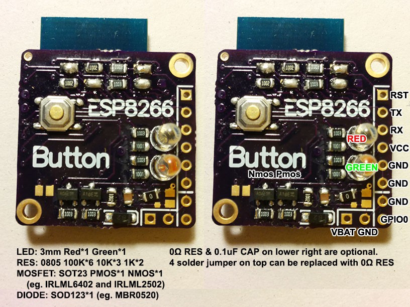
When all parts are soldered. You can connect VBat and GND to a 3~3.3V power source, Connect GPIO0 to GND (only for programming). And connect a 3.3V serial adapter to TX, RX and GND (Board TX to adapter RX, Board RX to adapter TX). When you get ready you can press the button and ESP module should be in download mode.
Trouble shoot: reconnect power and connect serial with 74880 rate and watch output. Press button and you should see something like "boot mode(x,y)". If you x is 1, means it is ready to receive firmware data. If it is 3, check if GPIO0 is connected to GND.
And you can refer to makenburn.bat to burn firmware to module. Or you can use other tool to do it.
Trouble shoot: reconnect power and connect serial with 74880 rate and watch output. Press button and you should see debug data of the board.
 deqing
Discussions
Become a Hackaday.io Member
Create an account to leave a comment. Already have an account? Log In.