-
1Step 1
instructions for building the first sensor controller node.
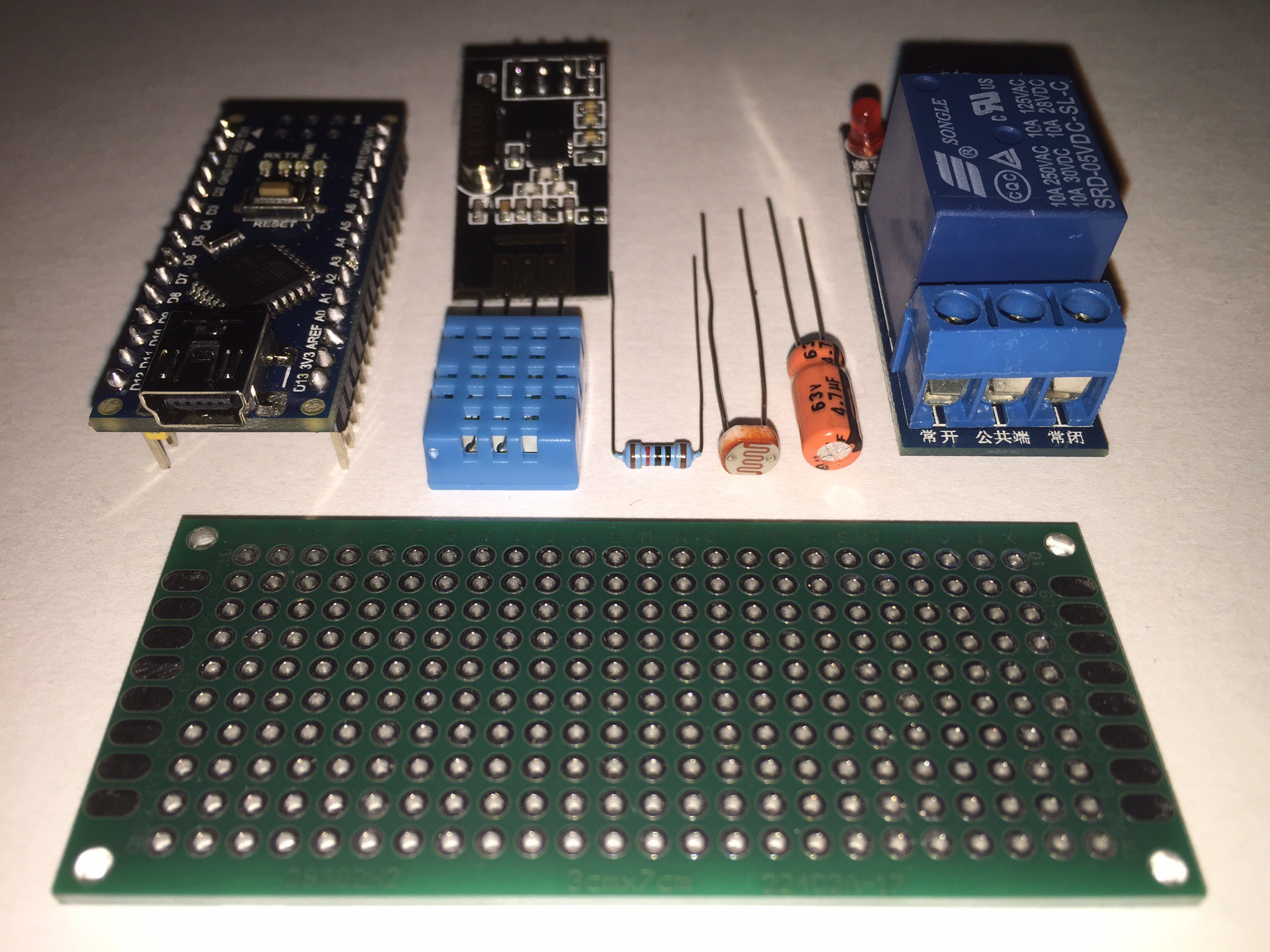
Parts required:
- Prototype board (3cm x 7cm)
- Arduino nano
- RF transceiver (NRF24L01)
- Temperature/humidity sensor (DHT11)
- 1-2 relays
- Light sensor (LDR)
- 4.7uf capacitor
- 10k resistor
- Wires and solder
![]()
-
2Step 2
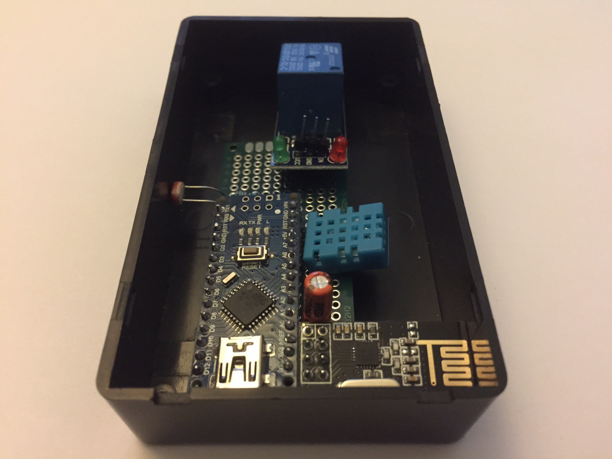
Choose the best layout and parts for what you need to sense or control.
Lay the parts out on the prototype board so that it fits into a case.
Start by putting the wires in place and the smaller components around the edge of the board with less connections.
![]()
-
3Step 3
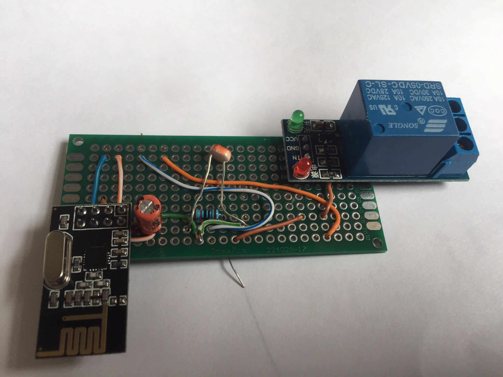
Always try and get the wires in place before the component as this will keep the wires organised and they can be hidden under some components.
I am using a solid core wire (from a stripped down CAT5 network cable) this is great as it stays in place, but it does snap quite easily.
![]()
-
4Step 4
As you are connection the components to the board, use a multimeter to check the circuit (using resistance setting). This prevents the lengthy task of removing solder from components if things don't work.
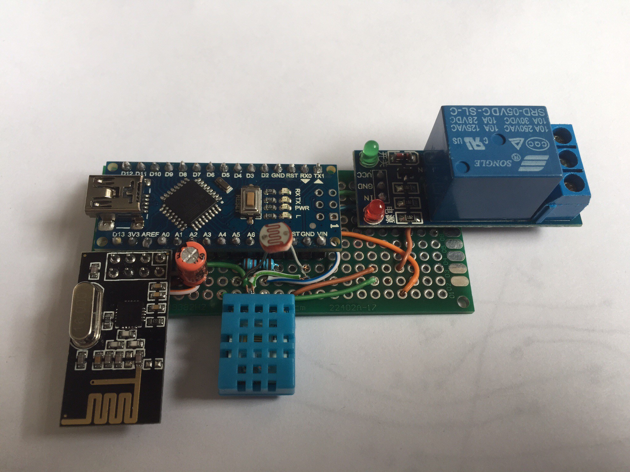
Here is the finished board, currently with just one relay but the wires are already in place for a second relay that can be added easily if required.
![]()
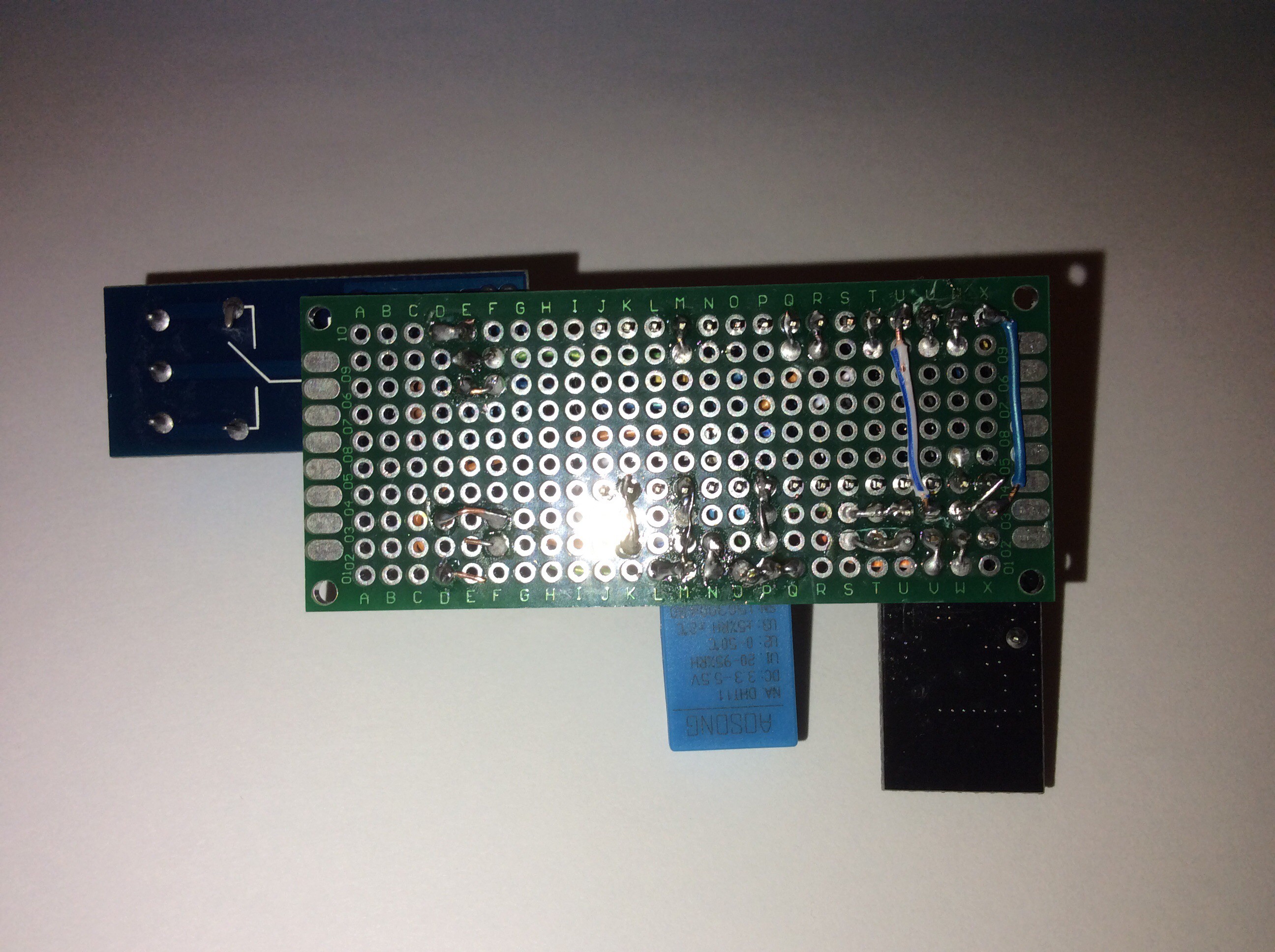
And the back of the board, with a few connectors bridged with wire and just a couple of wires on the back of the board.
![]()
Home automation using RF mesh network and arduino
Creating home automation sensors and controllers that can be used around the house forming a mesh network for communication
Discussions
Become a Hackaday.io Member
Create an account to leave a comment. Already have an account? Log In.