Aleks Clark
-
Parts arrived, soldering time!
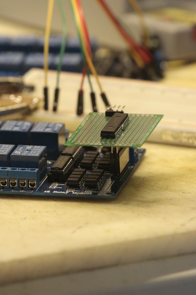
05/28/2015 at 22:27 • 0 commentsMan it would be really nice to have something better than this lame-o hand helper for the soldering. I really don't like jumping wires all over the perfboard, so I soldered some stackable headers right under the I2C port expander:
![]()
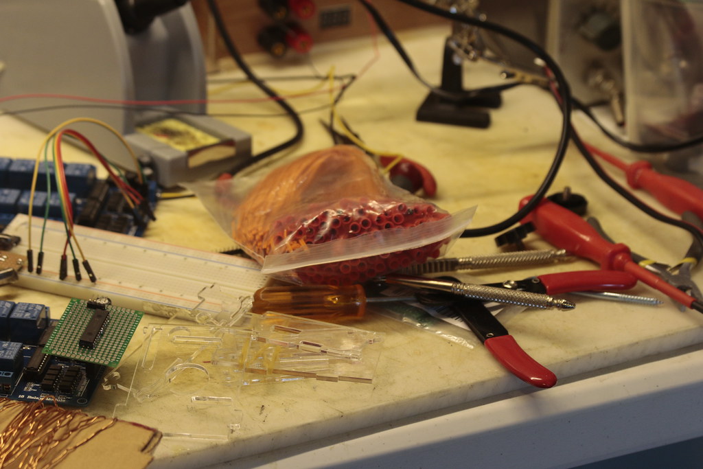
The rest of the parts showed up as well:
![]() The relay board actually expects the pins to be pulled to ground to activate the relays. That should make initialization...interesting. Obviously don't want those relays clicking on and off while we're booting up, and the fireworks are all loaded. Speaking of fireworks, here are the igniters:
The relay board actually expects the pins to be pulled to ground to activate the relays. That should make initialization...interesting. Obviously don't want those relays clicking on and off while we're booting up, and the fireworks are all loaded. Speaking of fireworks, here are the igniters:![]()
100 count for ~$25. Will need another bag or so. Ignition time at 3.3V was satisfyingly fast, fractions of a second. Jamming some green fuse in there worked like a charm, so I'm not expecting any problems at 12V.
-
Bad Ideas, Good Ideas
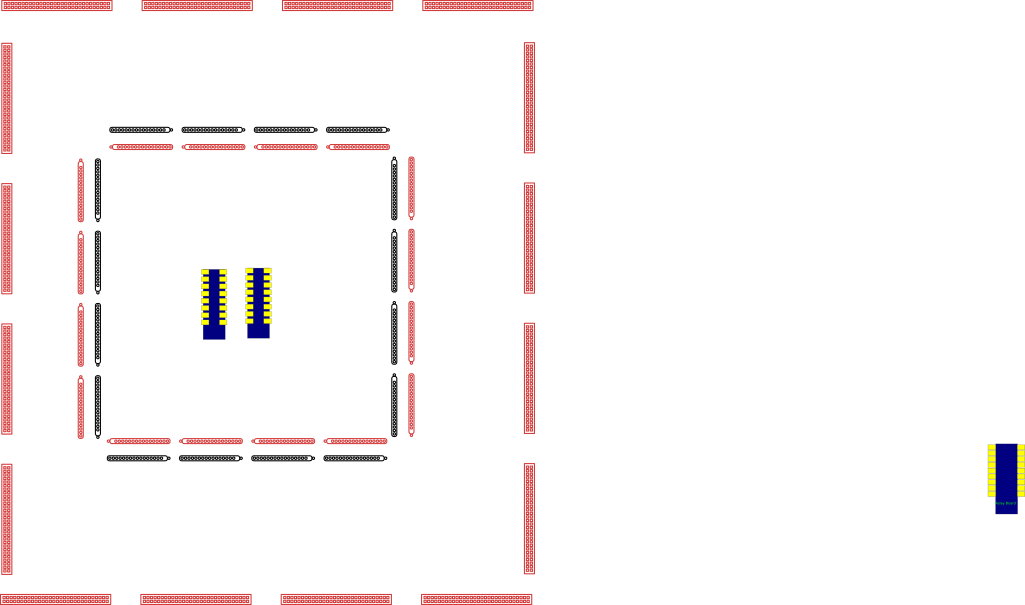
05/13/2015 at 20:12 • 0 commentsSo, was thinking about actually getting all of these 256 channels broken out to terminals, and the thinking went somewhat like "connect 16 wires to each relay, then distribute". That progressed until I ended up with something like:
![]()
two relay boards, surrounded by 32 16-connection busbars, breaking out to 16 30-position screw terminals. At this point I'm thinking "screw it, we'll just have 32 channels, direct-wired to the relays, and call it a day". The cost of all the busbars and terminals at this point has exceeded the rest of the materials for the project, there's just no way 256 channels is happening. In fact, it gets worse, because you may have noticed that even 16 30-pos terminals doesn't bring us to the full 512 connections needed, despite the rat's nest that would ensue in trying to wire up something like the above.
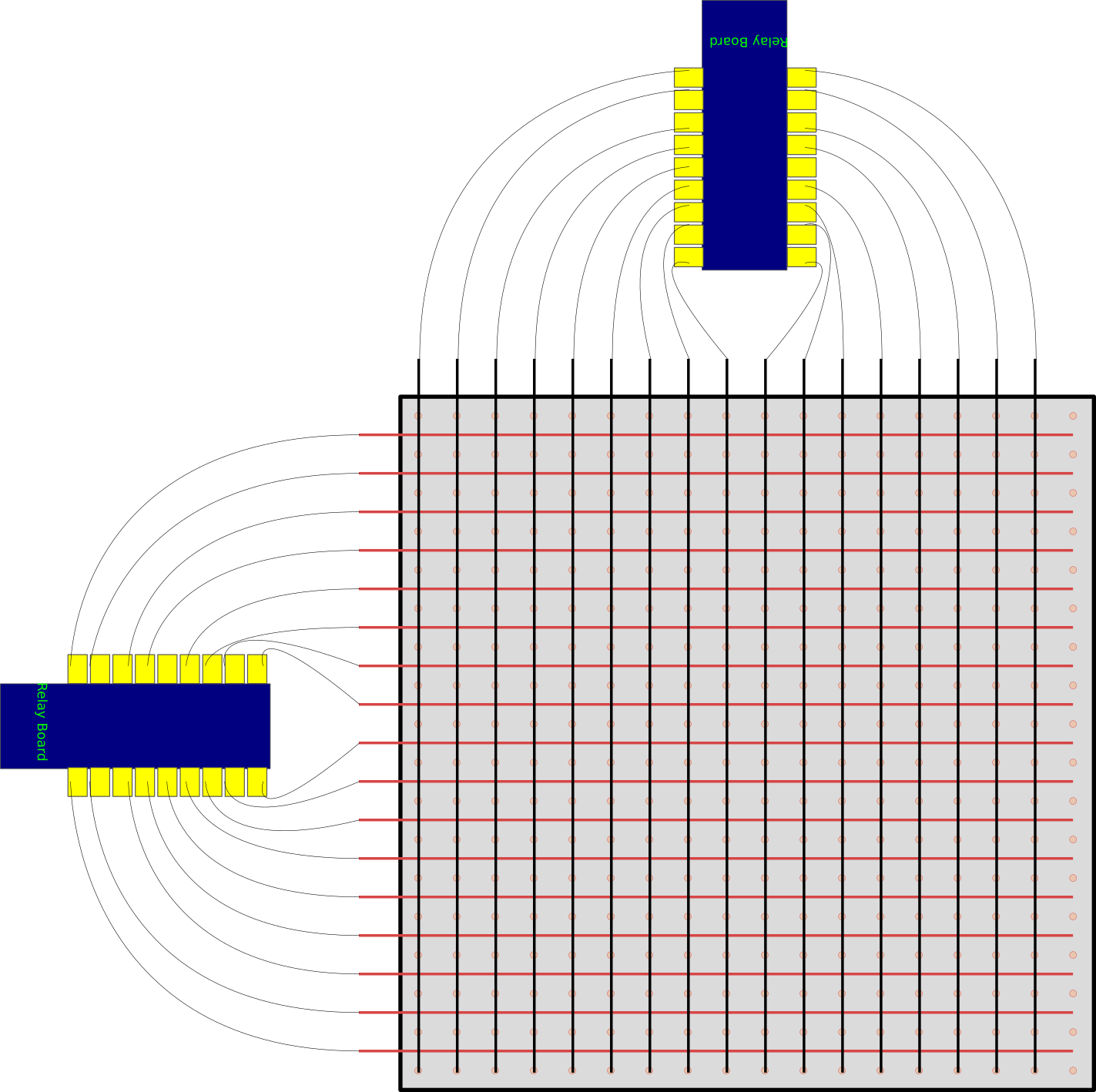
Enter LED matrices! Or any other kind of matrix arrangement, like what I arrived at:
![]()
The concept here is to take a 18"x18" sheet of perfboard, and put the negative wires on the back, and the positive ones on the front. Use bare copper wires on the board, and secure with something. Line up the negative wires with the holes, and solder PCB screw terminals between the positive and negative wires, with the terminal post going through the hole to the other side of the board to connect to the negative rail. I'll probably use some high-temperature polymorphic resin (aka hot glue) to give the terminals a bit of mechanical stability, but this should make for a compact arrangement that's straightforward to troubleshoot. Heck, I might even add LEDs to each terminal just to verify/monitor the operation of the board :)
-
Parts ordered!
05/08/2015 at 19:39 • 0 commentsuh, that's about it. eta 2-3 weeks.
256 Channel Firework Controller
Use two cheap 16-relay boards to multiplex and remotely control up to 256 channels of firey madness

 The relay board actually expects the pins to be pulled to ground to activate the relays. That should make initialization...interesting. Obviously don't want those relays clicking on and off while we're booting up, and the fireworks are all loaded. Speaking of fireworks, here are the igniters: