Aleks Clark
-
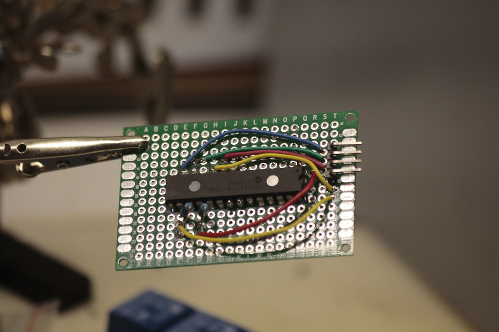
16x Board Design
07/06/2015 at 18:15 • 0 commentsI'll be using this to prove out the concept of an RJ-45 based interconnect
-
I2C woes
07/05/2015 at 12:41 • 0 commentswell, it half worked :P There was a significant amount of rain on the day, and despite multiple layers of tarps, we ended up with some water on the electronics, which wasn't good. The video shows how it worked while it was working. Even getting it to work for a little was problematic, one of the i2c chips just refused to have a reliable connection. Stay tuned for an in-depth assessment of why things didn't go well, and lessons learned from actually having to set up ~160 channels worth of igniters.
-
Sequencing
07/04/2015 at 15:44 • 0 commentsI'll have all the codes up on github after launch, but this is what the running firing sequence looks like this (the interval between firings was switched from seconds to milliseconds to make the video shorter)
-
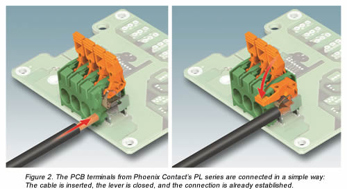
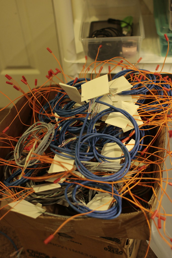
Igniter Cables
07/04/2015 at 15:41 • 0 commentsWell, this morning finished assembling igniter cables. Definitely going the RJ45 + push lock terminal route next time, something like:
![]()
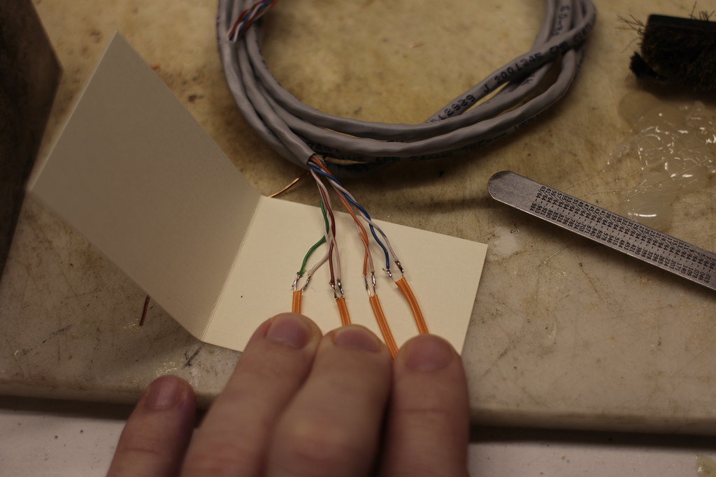
The current process goes like this:![]()
Solder![]()
separate wires on a piece of cardstock![]() add hot glue
add hot glue![]()
press down![]()
rinse, repeat many times
-
Victory!
07/02/2015 at 17:56 • 1 commentOk so hanging out in the collaboratorium turned out to be profitable - @Blecky prodded me until I figured out my problem with i2c. One of the MCP23017's had its SDA/SCL lines swapped, so every time I 'fixed' one, the other failed. Also, the RPi has pullups, so the pullups I added were not helping things.
After my i2c woes were sorted, I was able to successfully fire some igniters, whoo! 300ms is a bit short, I had to run the sequence a couple times to get them all to fire, so I'll use 600ms, and just write some code for firing groups simultaneously. Now it's time to make a bunch more cables.
-
Testing!
07/01/2015 at 10:35 • 0 commentsWell, small update cause the 4th is nearly upon us. Took the board outside, and it decided not to work. Yay. The problem seems to be on the i2c bus and/or the power/ground lines. I will either need to slow it down ( http://arduino-pi.blogspot.com/2014/03/speeding-up-i2c-bus-on-raspberry-pi-and.html ) or add additional pullups on the power lines. Unsure why it started failing all of the sudden, unless the humid air outside added capacitance somehow.
-
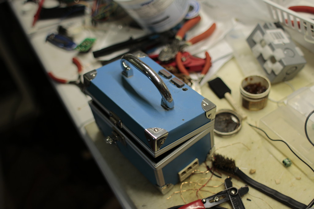
Power & safety
06/29/2015 at 14:14 • 0 commentsSo we definitely want to make sure nothing fires while putting things together. To that end, the relay boards will be powered separately from the RPi, and the actual firing power will be on yet another circuit. My junk stash yielded up this box, which was previously used for an arduino-powered quiz button system:
![]()
The existing nintendo power button will switch 12v to the relay board, and a salvaged printer power switch (the green blob in top/left) will switch firing power. Firing power will likely be 12v but it could turn out to be 48v if voltage drop is too high. I'll be adding binding posts for each circuit and screwing the box to the main sheet of plywood. -
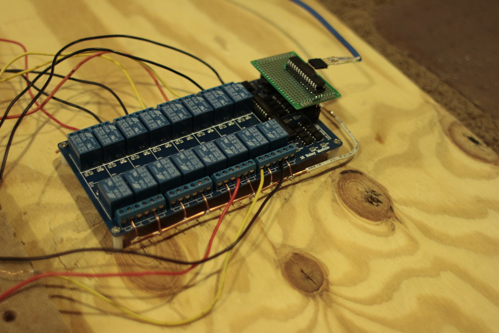
looks like we'll make it...
06/29/2015 at 11:27 • 0 commentsThe 4th is nigh but assembly is going smoothly. Still need to do some testing, but most of the boards are mounted in place. The terminals on the left were salvaged ones I hoped to use, but after I got started soldering them, I realized it would be nearly impossible to wire them since the wire openings face downwards.
![]() Scraping enamel off of magnet wire has been the least favorite activity in this project.....
Scraping enamel off of magnet wire has been the least favorite activity in this project.....![]() Here we can see the "bus" for one of the igniter power sides: just some thick solid core wire bent into a U-shape and partially stripped.
Here we can see the "bus" for one of the igniter power sides: just some thick solid core wire bent into a U-shape and partially stripped.![]()
-
Blinky Blinky
06/10/2015 at 12:26 • 0 comments -
Should have read the datasheet
06/10/2015 at 12:14 • 0 commentsWell, word of warning: the MCP23017 is definitely not indestructible. Second, NEVER hook up something that SUPPLIES 5v to a sainsmart 16 relay module unless the sainsmart is being supplied with 12v. The 5v will flow at high currents, seemingly powering the onboard regulator and making things "kind of" work for a bit, then the regulator gets hot, etc. It was bad.
Read the datasheet, not just the pinout :D
Here's the final protoboard, which ended up toast:
![]()
![]()
You can see where I severed the 5v connection in an attempt to salvage things. Fortunately I got 5 of the MCP23017, so we're not doomed yet!.
Subsequently, however, I put things on a breadboard:
![]()
And finally, I wrote up some go code to make clicky-blinky things happen!
256 Channel Firework Controller
Use two cheap 16-relay boards to multiplex and remotely control up to 256 channels of firey madness

 add hot glue
 Scraping enamel off of magnet wire has been the least favorite activity in this project.....
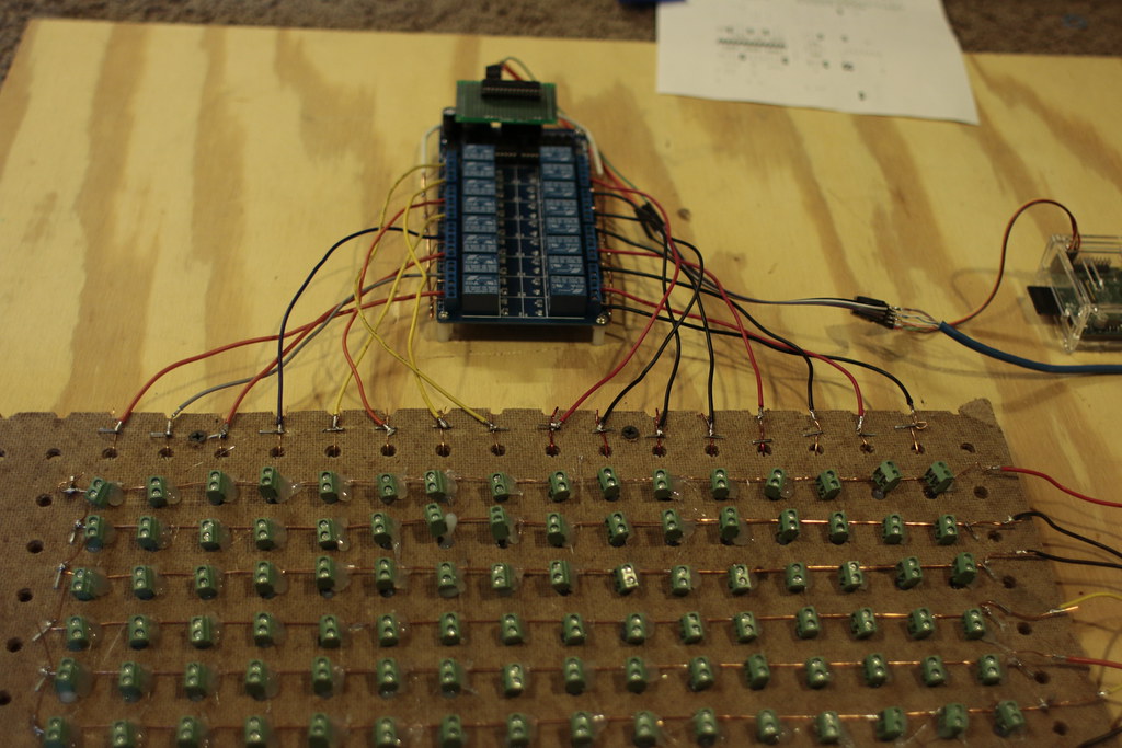 Here we can see the "bus" for one of the igniter power sides: just some thick solid core wire bent into a U-shape and partially stripped.