Crypto [Neo]
-
Even Cheaper PICxies? It might happen!
09/26/2015 at 22:35 • 0 commentsSo we finally managed to fill our open positions for the PICxie beta! Now we can finally focus on the actual beta rather than recruiting for it. We’ve ordered all of the parts and just as we calculated there was a 20% reduction in production costs. This recent data shows that we might be able to sell these for $44.99! Possibly even $39.99!! Something we are striving to achieve for you guys, we want PICxie to be a very accessible platform. We need 2 things to make that happen:
Demand/Volume
We need enough people to buy PICxies to reduce the costs of components, cables, and LiPo batteries. The batteries in particular cost us ~$2.00, but if we had a demand of 50-100 units we could order in bulk and get these for ¼ the price. At that demand the cost for components drops by about 50% as well.
Equipment
We really need a 3D printer in-house. We’ve already settled on the Form1+ (Possibly Form2) because it will have no issue printing the cube case that PICxie uses. The problem is we cannot afford to buy one based on our budget. Currently we spend ~$10 on each case, however with a 3D printer this would drop to 1/10th of the cost.
We can solve both of these issues rather elegantly with crowdfunding. Additionally this would generate PR which is ALWAYS good. We will be doing another Kickstarter, we like Kickstarter because it’s low risk to you guys financially, and well respected as a platform. We know exactly how much we need to raise in order to A) Fulfill rewards and B) Get the equipment we need to drive the cost even lower! We’ll post more about our Kickstarter after the beta units have been sent out.
-
Open Beta access for Sale!
09/23/2015 at 23:30 • 0 comments![]()
So we had quite a few people who did not respond to their beta e-mails, we contacted a lot of the other signups and a lot of people are not responding. If you signed up please check your spam folder. Since only 5/13 of our nominees actually completed the signup process, we have 8 spots open in our Beta program, if you would like early access to the PICxie 8-bit development kit, please check our store page at: http://www.moarobotics.com/products/devkits/
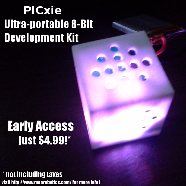
We’re no longer offering the free PICxie. Only people who have signed up in the before today will be receiving a free PICxie, others will have to pay $4.99 to access the program.
Open Source Initiative
Also on the product page are the source AND production files for PICxie, if you are interested in rolling your own PICxie unit, you can download all the files necessary on the product page! FREE! 100% Free. And please if you do so, please credit us and let us know! We’d love to hear about any changes you make to our platform or improvements you come up with. We also love to hear about any neat projects you use PICxie in, so please let us know! :D
-
PICxie Tutorial 1 - Controlling the RGB LEDs
09/18/2015 at 14:02 • 0 commentsIn this tutorial, we will cover the basic aspects of controlling the RGB LEDs present on the PICxie development kit.
Requirements
You will need the PICxie development kit, a USB cable for programming, Microchips MPLABX and XC8 software, and Mid-Ohio Area Robotics MOARProg software and PICxie Application Libraries installed on your PC. All of this will have came with your PICxie development kit.
You should at least know the difference between a bit and a byte, and know what hexadecimal and binary numbers are.
What are RGB LEDs?
RGB (Red/Green/Blue) LEDs look and function much like a typical LED, however, inside the LED package, there are actually three LEDs representing the primary colors, red, green, and blue. By controlling the brightness of each individual LED you can create pretty much any color you want.
We create colors just like you would mix paints together on a palette, by adjusting the brightness you control how much color (paint) is added to the palette! The reason that varying the amount of red, green, and blue light creates different colors is that your eye has three types of light receptors in it (red, green, and blue). Your eye and brain work together to convert the amount of each type of light into a color of the spectrum.
![image]()
In order to vary the amount of light we need to send a variable amount of power to each color inside the LED.
PWM Theory
This is accomplished with Pulse-Width Modulation, a very simple technique for controlling power. We are going to use it to control the brightness of the RGB LEDs. The diagram below shows a typical PWM signal, exactly like the one we’ll be using.
![image]()
We will be writing a program that produces a PWM pulse about every .5 milliseconds. The length of this pulse will be controlled by 3 variables representing the red, green, and blue colors. These variables have a range of 0-255, so ‘R = 0” will not produce any pulse at all and 'R=255’ will produce a pulse that lasts all the way until the end of the pulse, effectively turning that color on completely. If we set that variable to something in between 0 and 255, we can vary the brightness of the LED. A value of 13 will turn the LED on about ~5%, and a value of 230 will deliver about 90% of the power. The human eye cannot see the LED turning on and off that fast, so to our brain it appears as if the brightness is changing. Getting Started with MPLabX and PICxie
Before we dive into coding, the project needs to be created in MPLabX.
1. Start by opening MPLabX, and clicking File > New Project…
![image]()
2. Choose 'Microchip Embedded’ for the project category, and 'Standalone Project’ for the type of project. Click next![image]()
3. The next screen lets us specify the type of device we will be programming. PICxie uses a PIC18F26J50 and that is the device you’ll want to enter into the Device field in this window.
4. Click next through the 'Select Tool’ window, ICD3 should be selected already (although we will not be using it)![image]()
5. For the compiler, select the XC8 compiler and click next
6. Enter the project name of your choosing, we will be calling ours Tutorial_1. Leave the other options alone, and click Finish. Your screen should look very similar to following image![image]()
7. Almost done! In the left hand list, make sure the top panel is set to the 'Project’’ tab, then right click on “Tutorial_1” and click 'Properties…’![image]()
8. Go into the “XC8 Linker” category, and from the drop down select 'Memory model’, and in the 'ROM ranges’ field, enter 'default,-0-FFF,-FC00-FFF7’ and click apply![image]()
9. Click the drop down again, and select 'Additional options…’ and in the 'Codeoffset’ field enter '0x1000’ and click OK.We are now ready to start coding programs for PICxie!
Coding the Basics
Now that we have everything setup, lets write a program that will cycle the RGB LEDs through a bunch of different colors. In the left hand projects listing, right click on 'Tutorial_1’ again, and select 'New’ then click 'C Source File’
![image]()
Name the file something recognizable, a common name for the initial file in a C program is 'main’ so we have named our file accordingly. Click OK and the file will be saved to your project folder and opened in the editor within MPLabX.
The first code we want to write is some code to include our PICxie Application Libraries, as well as the XC8 delay library.
![image]()
Next we need to write our main entry point, where the code will begin executing from when it is loaded onto PICxie. This is simply a C function called 'main’ (Note the lowercase letter M) with a void return value.
![image]()
All of our code from this point forward will go between the curly braces of this function. The first thing we need to do is set all of the input/output pins on PICxie to be outputs, when a microcontroller resets there’s some things that get reset, and others that don’t. The best place to check for this information is in a document called the 'Datasheet’. This document covers, in detail, every function and detail, of the PIC18F26J50 that is contained in PICxie. Since this is a basic tutorial we’ll skip the heavy reading and try to cover the details.
The I/O pins on the device are divided up into 3, 8 pin groups called Port A, through Port C. Each of these Ports has 3 registers associated with it, a tri-state register to control if the pin is an input or an output called TRISx, a latch register that lets the user control the output state of the pin called LATx. For the RGB LEDs, the I/O Port C contains the 3 pins that we will use to control the LEDs.
In the C programming language, local variables need to be declared at the beginning of the function, so lets do that first. We’ll use the char type since we want to use 8-bit values whenever possible on an 8-bit processor like the PIC18F26J50.
![image]()
And below that we’ll setup the I/O ports on the device. We show three different ways of clearing all of the tristate buffers to be outputs, this state is desirable because it uses the lowest power.
![image]()
The next step, we are going to be increasing and decreasing the brightness of each color in sequence. From Red → Red/Green → Green → Green/Blue → Blue → Blue/Red → Red Again. Since the code is repeated multiple times, its a good idea to create a macro called IncreaseBrightness(x) and DecreaseBrightness(x) to make our code cleaner.
![image]()
In these inline functions we increase/decrease the x variable appropriately and check to see if we’ve reached the minimum or maximum values. If we have, we increment our state (to move to the next sequence) and delay for about 2 milliseconds.
Now we can into the part of the code that controls the PWM, all of this code will repeat forever, so we stick it in a while loop.
![image]()
Next, each loop we will increment our PWM counter to update our position in the period, additionally we’ll check if it’s greater than or equal to our pulse_period variable, if so we reset it back to 0.
![image]()
Directly afterwards we need to increase or decrease certain colors based on our stateBy using the switch statement, and the macros we created earlier, we can write this in a pretty compact package given that it would be much longer and repetitive without them. This is arguably the biggest section of code in our entire program.
The final section of our code will actually turn the LEDs on and of in response to the PWM we set up earlier.
![image]()
The RGB LEDs are connected with 3.3v on one end and expect ground, or 0V, on the other pin. When we turn a pin on and off we are actually raising to 3.3V and lowering it back down to 0V. So, to turn an LED off we actually have to turn the microcontroller I/O pin on so that there is 3.3V on either side. In this situation current doesn’t flow and the LED will not light.
The 3 if statements check to see if the LED should be on based on where we are at in the pulse_period by comparing our desired period in RED/GRN/BLU to the counter. If it matches we turn that on by performing a logical AND with LATC for each colors respective I/O pin. The proper way to do this would be to additonally use OR statements to turn the pin off if it’s greater than pulse_counter, this is an exercise left up to the reader.
Last we delay for about 40 microseconds to slow down the pulse period to a level that we’ll actually be able to appreciate.
Building the Project
The final step now that we’ve written our code is to actually build the project so we can program it onto PICxie. If you look a the toolbar at the top of the screen you’ll see several buttons.
![image]()
Clicking either of the circled buttons will build or project, if all goes well you’ll see something similar to below in the output screen.
![image]()
We can now close out of MPLabX, we’re finished with it for this tutorial!
Programming PICxie
To load our program onto PICxie, first make sure PICxie’s power switch is set to OFF, then connect the included USB cable to the PC, and then connect it to PICxie. The charging LED should blink briefly, and will turn on fully if PICxie’s battery is below a full charge. Open the MOARProg software, and turn PICxie on.
![image]()
Open the file that was built by MPLab by clicking File → Open File, and navigating to the directory you saved the project. The program will be in the folder “dist/default/production/”. Once loaded click the program button
![image]()
And the program will be downloaded to your PICxie
![image]()
Seeing your Work
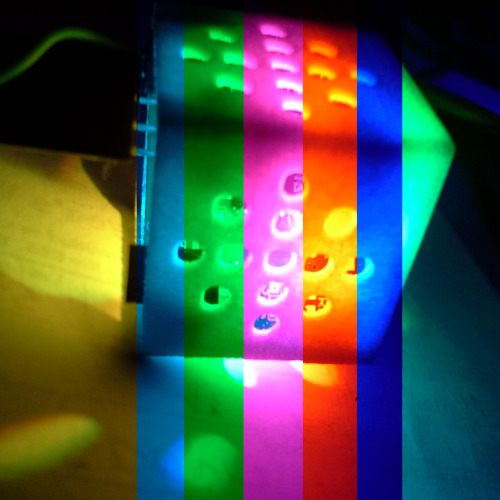
Turn off your PICxie, and unplug it from the computer. Then turn it back on, and your PICxie should light up with a rainbow of colors
![image]()
Conclusion
That concludes this tutorial, a zip file containing the source code for this project can be downloaded from:
http://www.moarobotics.com/support/tutorials/Tutorial_1.zip
If you have any questions, comments, corrections, or ideas for improvements to this tutorial; please e-mail customerservice@moarobotics.com!Appendix A – Full Code Listing
// <PICxi.h> #include <xc.h> #define _XTAL_FREDEQ 48000000; #pragma config WDTEN = OFF //WDT disabled (enabled by SWDTEN bit) #pragma config PLLDIV = 12 //Divide by 3 (12 MHz oscillator input) #pragma config STVREN = ON //Stack overflow/underflow reset enabled #pragma config XINST = OFF //Extended instruction set disabled #pragma config CPUDIV = OSC1 //No CPU system clock divide #pragma config CP0 = OFF //Program memory is not code-protected #pragma config OSC = HSPLL //HS oscillator, PLL enabled, HSPLL used by USBLU #pragma config T1DIG = OFF //Sec Osc clock source may not be selected, unless T1OSCEN = 1 #pragma config LPT1OSC = OFF //high power Timer1 mode #pragma config FCMEN = OFF //Fail-Safe Clock Monitor disabled #pragma config IESO = OFF //Two-Speed Start-up disabled #pragma config WDTPS = 32768 //1:32768 #pragma config DSWDTOSC = INTOSCREF //DSWDT uses INTOSC/INTREDC as clock #pragma config RTCOSC = T1OSCREF //REDTCC uses T1OSC/T1CKI as clock #pragma config DSBOREN = OFF //Zero-Power BLUORED disabled in Deep Sleep #pragma config DSWDTEN = OFF //Disabled #pragma config DSWDTPS = 8192 //1:8,192 (8.5 seconds) #pragma config IOL1WAY = OFF //IOLOCK bit can be set and cleared #pragma config MSSP7B_EN = MSK7 //7 BLUit address masking #pragma config WPFP = PAGE_1 //Write Protect Program Flash Page 0 #pragma config WPEND = PAGE_0 //Start protection at page 0 #pragma config WPCFG = OFF //Write/Erase last page protect Disabled #pragma config WPDIS = OFF //WPFP[5:0], WPEND, and WPCFGRN bits ignore // <PICxie.h> #include <delays.h> #define IncreaseBrightness(x) x++; if(x == 255) { state++; Delay1KTCYx(25); } #define DecreaseBrightness(x) x--; if(x == 0) { state++; Delay1KTCYx(25); } void main() { // Variables to control the RGB Led colors unsigned char RED = 0, GRN = 0, BLU = 0; // Variables to control the PWM state unsigned char pulse_counter = 0, pulse_period = 255; // Variable to control the state unsigned char state = 0; // Set all pins on the device // to outputs TRISA = 0b00000000; // Binary TRISB = 0x00; // Hexidecimal TRISC = 0; // Normal Number while(1) { // Increment the pulse counter pulse_counter++; // Once the pulse is complete reset and update // the color cycle. if(pulse_counter >= pulse_period) { pulse_counter = 0; // Cycle through a bunch of pretty colors switch(state) { case 0: IncreaseBrightness(RED); break; case 1: IncreaseBrightness(GRN); break; case 2: DecreaseBrightness(RED); break; case 3: IncreaseBrightness(BLU); break; case 4: DecreaseBrightness(GRN); break; case 5: IncreaseBrightness(RED); break; case 6: DecreaseBrightness(BLU); // At the end of this cycle // RED is already on so we should // return to state 1 if(state == 7) state = 1; break; default: state = 1; break; } // End Switch } // End If // Update the duty cycle of the PWM period LATC = 0b00000111; if(RED <= pulse_counter) LATC = LATC & 0b11111101; if(GRN <= pulse_counter) LATC = LATC & 0b11111011; if(BLU <= pulse_counter) LATC = LATC & 0b11111110; Delay100TCYx(5); } // End While } // End Main -
PICxie Open Beta Test
09/09/2015 at 11:28 • 0 commentsSo if you are interested in beta testing PICxie, please click the link below.
http://goo.gl/forms/GePDxUB1JC
If you’re selected you’ll receive the following a PICxie ultra-portable development kit ABSOLUTELY FREE. You have NOTHING to lose so click the link for more details :D
We will be selecting our Beta testers Friday of next week and will not be accepting any new signups thereafter!!Updates updates updates
PICxie is working remarkably well, we actually decided to add a small IR emitting LED so that way multiple PICxies can talk to each other wirelessly! This should make for some interesting applications!
The battery we ended up choosing was actually 50% higher capacity than we planned! This was a great thing to find. PICxie in our tests averages a run-time of about ~20 minutes, but we’re also using a lot of the peripherals to get a high power consumption.
Having an SD card onboard is AWESOME, we were able to successfully locate a test file in the FAT filesystem and write data to it, then read that data back on windows! We used this to play a very short WAV file from the SD card.
We built a model rocket that we will be sending a PICxie up in,
http://www.321rockets.com/magician-SL3-model-rocket-kit.htmlIt’s quite formidable looking, we plan to log data such as altitude and temperature as well as G-forces, local magnetic field strength, and orientation. We’ll be making a video and the log data available for your viewing pleasure when the weather is favorable for launch :D.
-
The Big Question
08/11/2015 at 01:41 • 0 commentsSo if you’ve been following the development and news about our latest project you might be left asking yourself one question -
What exactly is PICxie?
“PICxie is a ultra-portable development kit for Microchip Technology microcontrollers.”
We’ve taken the traditional idea of a development kit and spun it around on its head! We’ve taken most of the features you’d expect in a development kit and shrunk it down and crammed it into a 1 inch cube!
![]()
PICxie has a built in microphone and speaker combination, full-color RGB lighting, a MicroSD card slot, and an internal rechargeable lithium battery and more! PICxie is loaded with powerful suite of features letting you writing cool programs that can do things like:
- Log the local temperature, altitude, barometric pressure, orientation, acceleration, or any combination thereof! (Think of a something like a blackbox for RC planes!)
- Sound detection and recording
- Servo motor control
- IR signal detector
- Local magnetic field strength detector/logger
- And more!
And the 4-pin breadboard compatible I2C expansion bus (I2C and 3.3v Power)and extremely small size make it possible to power your projects with PICxie! We’ve used PICxie to make interesting things like:
- Model rocket altitude, orientation, and GPS location logger
- Mobile robot
- Burglar Alarm
- Universal Remote Control
- Wireless environmental monitoring
- And MUCH more!
Who will benefit from PICxie?
PICxie is a powerful and robust platform for learning embedded development and coding, and is a perfect complement to intermediary STEM courses focused in those areas. It’s also great for anyone with a serious interest in those fields, as it will teach you how to interface with things like IR receivers and MEMS devices, and use the I2C bus to interface with your own hardware on a breadboard.
Why should I choose PICxie over any of the other development kits out there?
Three simple words: Size, Cost, and Functionality. When designing PICxie we already had a good idea of what the competition was. Our main realization was that the cheap ones had no features and were simply a bit more than a break-out board for the MCU. The feature rich ones are usually more expensive, and are definitely not as portable. With PICxie you get 90% of the product in a 90% smaller package!
OK…but how much will it cost?
![]()
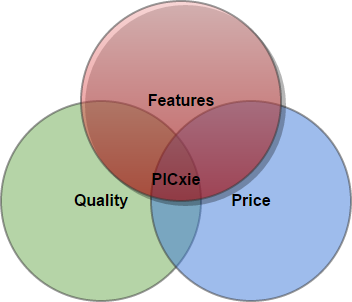
If you’ve spent anytime near a manufacturing or engineering environment you should be aware that out of the following: Quality, Price, and Features; you can only pick 2. Here at MOARobotics we thought that we could beat that thinking and created a product that could encompass all three categories.
$54.99USD!
PICxie costs a mere $59.99USD and could potentially get cheaper depending on demand! Right now our two biggest hurdles are the casing and components. Both of those get cheaper in volume and extrapolation tells us that we COULD potentially offer PICxie for ~$35-$40.00USD depending on how popular PICxiewas.
Kickstarter - Bringing it all to the masses!
We will be launching a Kickstarter for PICxie! This project culminated in a product that we feel fills a void in the market for a affordable and portable development kit. We primarily need the Kickstarter for the following reasons:
- Bringing our product out into the market
- Developing new products in the future
- Buying equipment to make our products even more affordable
- Simple publicity
PICxie is already set to go we just have to draft up our Kickstarter, get a nice presentation video made, drum up some momentum, and conduct our beta test prior to doing it. We think you’ll really like PICxie, and with your help we can bring a really great development kit out into the market! Speaking of betas…
PICxie Beta B
If you’re one of the people who like free stuff (and who isn’t :)?) and are interested in getting a FREE PICxie to try out, please signup here, we have about 87 signups at the time of the writing, but only 10-25 people are going to be selected. Signup today for a chance to be an official beta tester for PICxie! As a reward you get a free PICxie and also will be listed as a Beta Tester on the product page and in the manual.
PICxie Beta Signup!So what’s next?
If all goes well we’ll be offering several versions of PICxie in the future. We actually already have an AVR version of PICxie but we need to verify the circuit before we can go ahead with it. We also have a PIC24 and PIC32 version. We also have a slightly bigger version (2.5″ cube) that is based around an FPGA. We’d love to have a reason to make these versions, and if you’re interested we’d love to hear from you!
Also we’re VERY open to suggestions on what PICxie needs and what it doesn’t, and we love hearing feedback from our users. Like PICxie? Let us know! Don’t like it? Tell us why! It’s only with your feedback that our products can get better.
-
MPLABX
06/23/2015 at 00:19 • 0 commentsSo we got the new ICs today and immediately switched out the PIC18F26J50 that was bad with a new one and we now have USB! YAY! Unfortuantely we hit another snag because for whatever reason, when our code is compiled with MPLabX it will not run when loaded on PICxie. The bootloader comes up fine, and we can load it, and it verifies perfectly. But PICxie just sits there.
If we build the EXACT same code but use MPLab v8.92 everything works fine, we're not really sure whats going on, but until we get it resolved we're going back to MPLab v8.92 so we can actually get some demos going!
-
PICxie is born!
06/17/2015 at 14:52 • 0 commentsSo we’ve been putting PICxie through it’s paces, one disappointing thing that seems to have happened is that the PIC18F26J50 that we got seems to have a bad USB transceiver! No matter what we do we can’t get the USB the respond. We have 3.3v on the VUSB pin, the oscillator signal is very clean. There is continuity between the end of the cable and the pins on the PIC. After a lot of head scratching we finally just put a project on that had only this code:
UCON = 0;
UCFG = 0;
UCFGbits.UPUEN = 1;
UCFGbits.FSEN = 1;
UCONbits.USBEN = 1;
On the prototype this causes the device to be detected, on the current assembled PICxie nothing happens. All the relevant pins are exactly the same voltage between the two, so at the point we can safely assume the PIC is at fault which isn’t common, but at least now we can order a new one and get the USB bootloader tested.As far as the other hardware it’s all working, and we have the ICSP port so we can test everything still. We took a trip from Columbus up to Johnstown, and it was awesome to be able to log the temperature, altitude, barometric pressure, and magnetic field strength during the trip. We’re already working on a GPS module that you can place PICxie into because we’d like to make it easy to be able to correlate the data to the GPS location as well.
![]()
I apologize for the colors not being in proper order ^_^ but here is some bonus assembly PICs to make up for it.
![]()
We’ll have more PICs and hopefully a video or two up this weekend some time so stay tuned!!
-
Now 45% smaller!
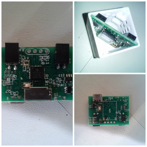
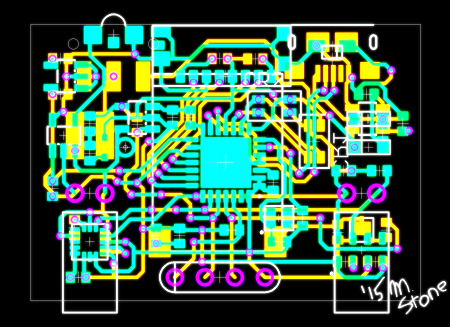
05/14/2015 at 17:36 • 0 commentsSo when we did the 48hr challenge we were under a time limit, so if we had to increase the size of the form factor to compensate for the challenge we did so. This lead to a package that was 14% bigger and 68% longer than what was originally intended. We decided to do something about that.
![]()
This PCB only measures only 33x23.4mm compared to 35x35mm. This means our case will be able to be shrunk down to a 1" cube. Yippee! It still has everything we've mentioned before, we didn't cut anything :)
We could probably make the design even smaller but it would be about $5 more expensive. Right now the chip speaker hogs a LOT of the PCB. When we were researching parts we were surprised to discover using the PCB mounted components was actually cheaper than using traditional wire-lead speakers and microphones.
-
Waiting
05/12/2015 at 23:29 • 0 commentsSo we've ordered all the stuff for the very first PICxie :D, we're really excited, hopefully it'll all be here soon! We expedited everything we could. It costs about $60 to make one of them, which isn't bad! Of course those are per unit prices which always go down when we get to make stuff at a larger volume.
We're anticipating selling PICxie for ~$40-50 dollars depending on the kind of response we get PR wise.
I spent yesterday going over everything with the team and we can't find any obvious errors or issues with the design. Yay! Very impressive for 37hrs worth of work.
We took the files to make your own PICxie down for a few of reasons:
- This is a new design, and we don't feel OK letting anyone spend money that might be wasted on something that may have faults
- We've had an incredible response to PICxie, a lot of people really like it, so we might just kickstart it! Afterwards we'll be releasing all the files for sure if we do that.
We have a couple of good demos written for the PICxie already: A magnetic field indicator, a orientation sensor, and an enviornmental logging demo.
The last one we're really excited about because we're planning on putting PICxie into the payload compartment of a model rocket and log things like local magnetic field strength, barometric pressure, altitude, orientation, etc.
-
48hr Challenge Recap
05/11/2015 at 04:48 • 0 commentsAlright so I've posted the production files on the project page for you to download, there is a Bill-of-Materials, use this as a guide to locating parts on Digikey, tomorrow I'll update it with a BOM that has links to all the parts and prices after I order them.
The PCB Gerber files should be sent to Elecrow, with the service I just linked you should be able to get 10 PCBs,
The Case STL files should be uploaded to Shapeways, or you can use the links to our shop page below.:
Last there's a couple of labels you can print out onto an adhesive label and put on the PICxie so you can tell what does what.
With all of that, a little intrepid digikeying, and rework station. You can make your very own PICxie ^__^ Be warned!!! this is a preproduction product (E.G. it's never been made before). I'll be ordering parts tomorrow and once I get the parts and build it I'll post detailed instructions.
PICxie
An ultra-portable development kit for Microchip Technology microcontrollers!