-
Blackbox is back on Hackaday!
07/31/2019 at 15:00 • 0 commentsI'm taking part in this year's hackaday prize with the blackbox project, so this project page will be discontinued!
You can find the new project page here: https://hackaday.io/project/166860-multitool-3d-printer-blackbox
I can use every support, it would be great if you like and share this project!
It's been a while since the last Log on Hackaday. The reason is that I had to abandon some cummincation channels in favor of some others. I used the time to build a compelling project page on my website, set up a community forum, and worked hard on getting the fusion files ready. That was a lot of work - and still is - but it's getting easier. Blackbox is now on a path to be a real community-driven open source project with many contributors.
I will post all significant updates on my Blog first and then spread it to different channels including Hackaday. Github won't be further used because it's just painful to use with 3D Files (File Size limit, upload and deleting procedure etc.). Primary source will be the Fusion 360 File where everyone is invited to participate. Fusion has a built-in version system, offers group projects and can directly export BOM files. All that makes it the perfect platform to collaborate.
Source files, BOM and latest Informations https://layershift.xyz/blackbox3dprinter/
Coordination for all builder and contributors is primarily on the Forum and discord.
-
Optical Tool Changer Calibration
01/30/2019 at 21:51 • 0 comments![]()
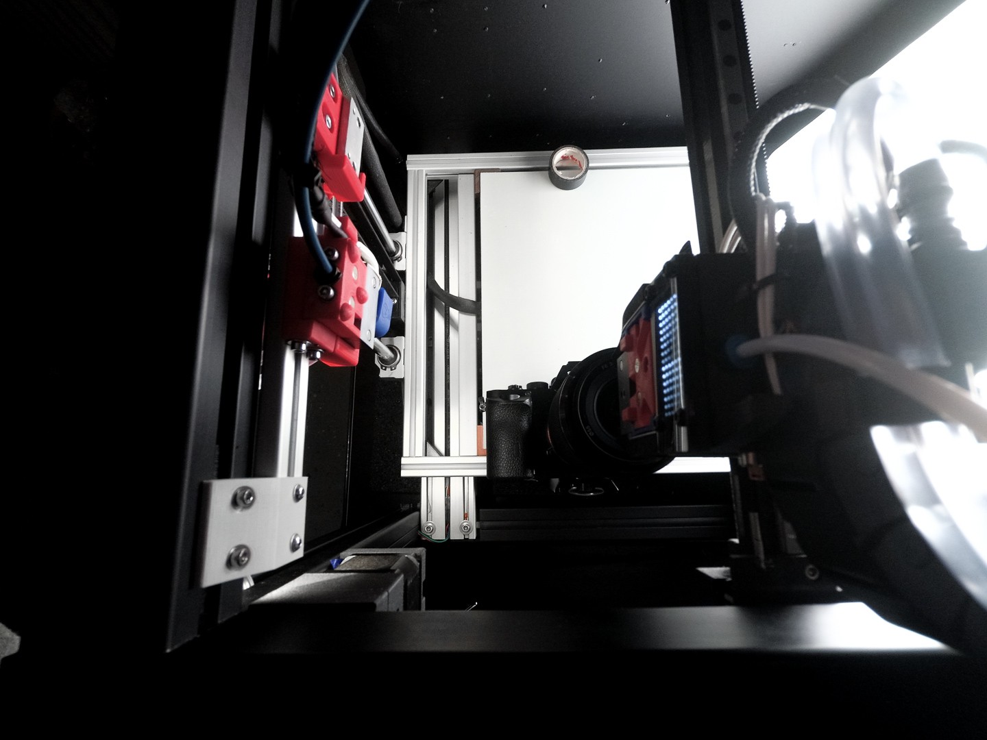
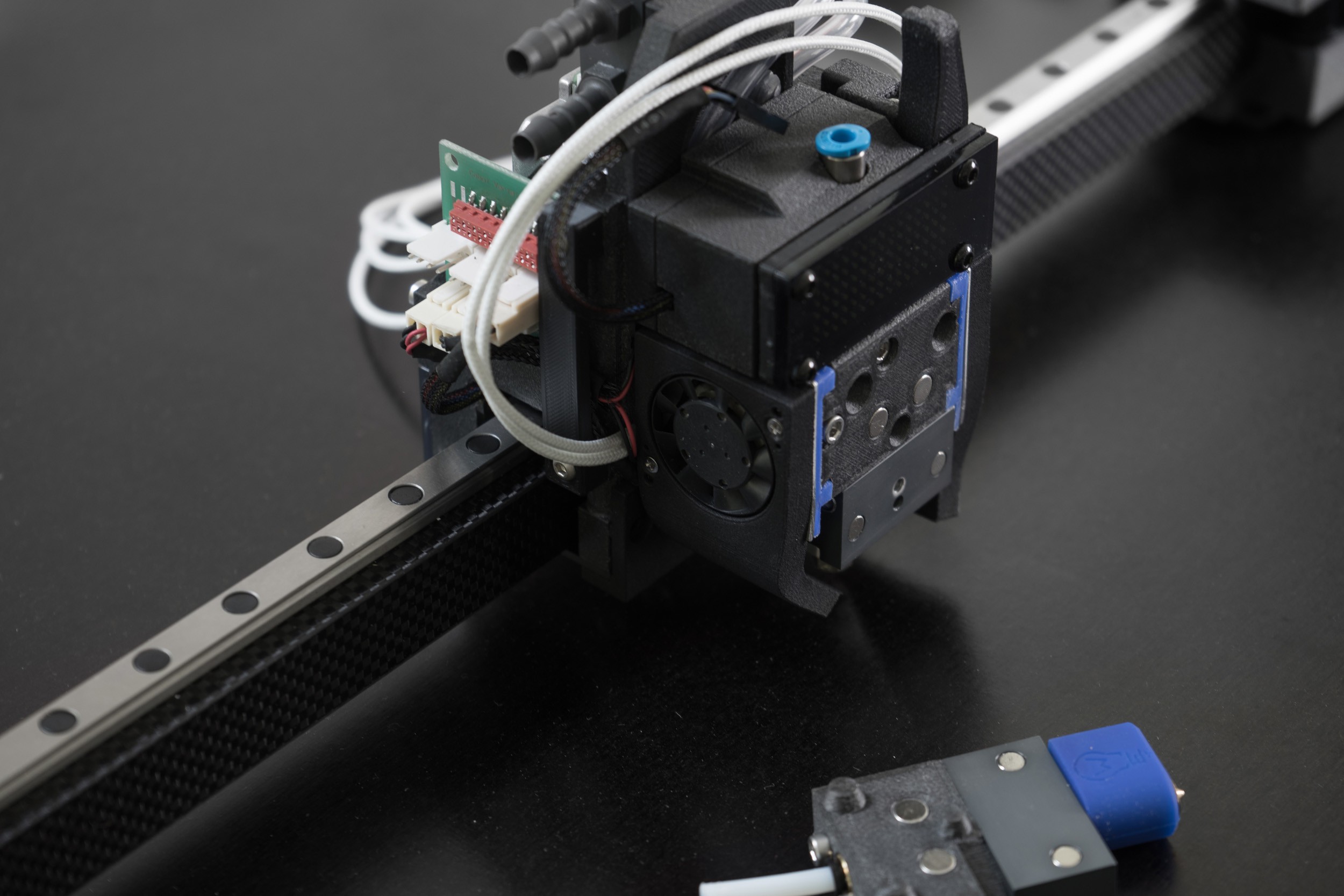
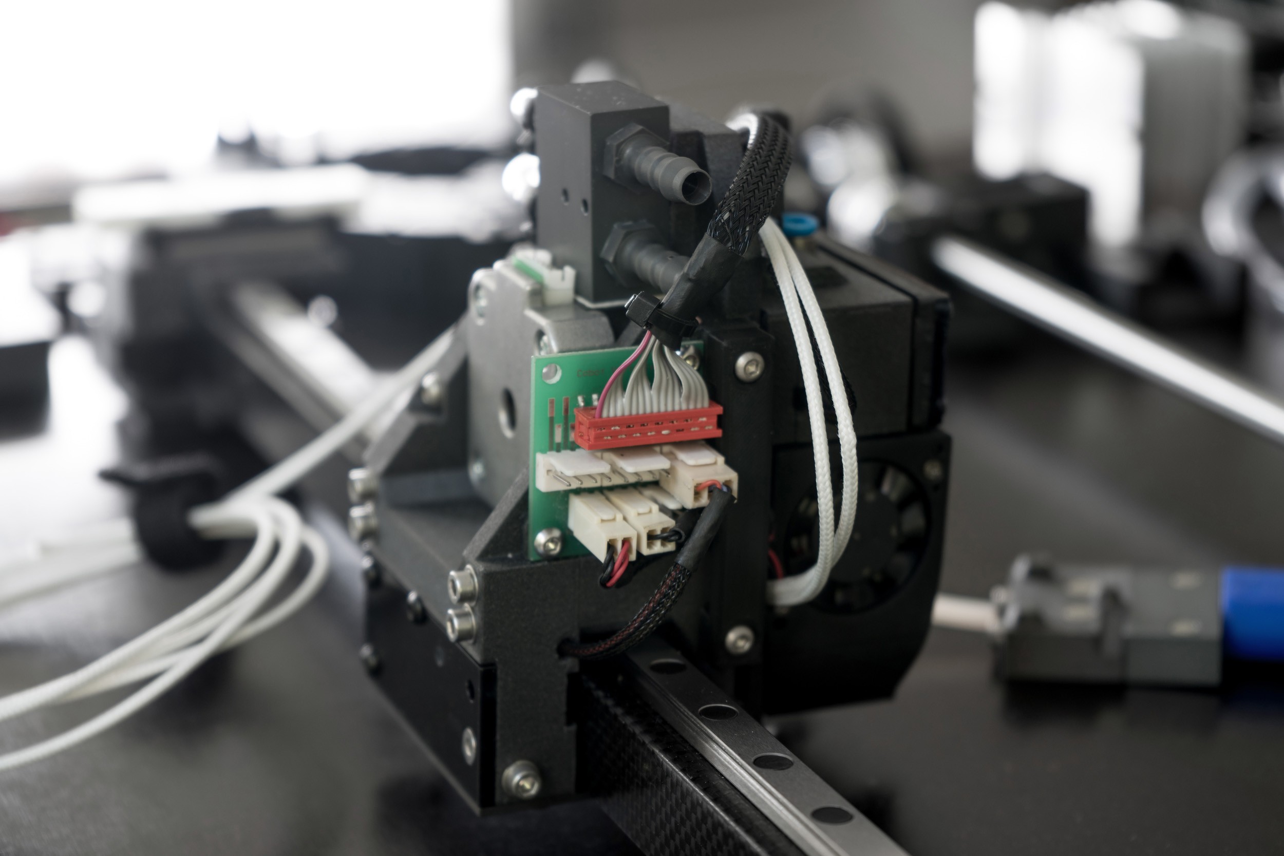
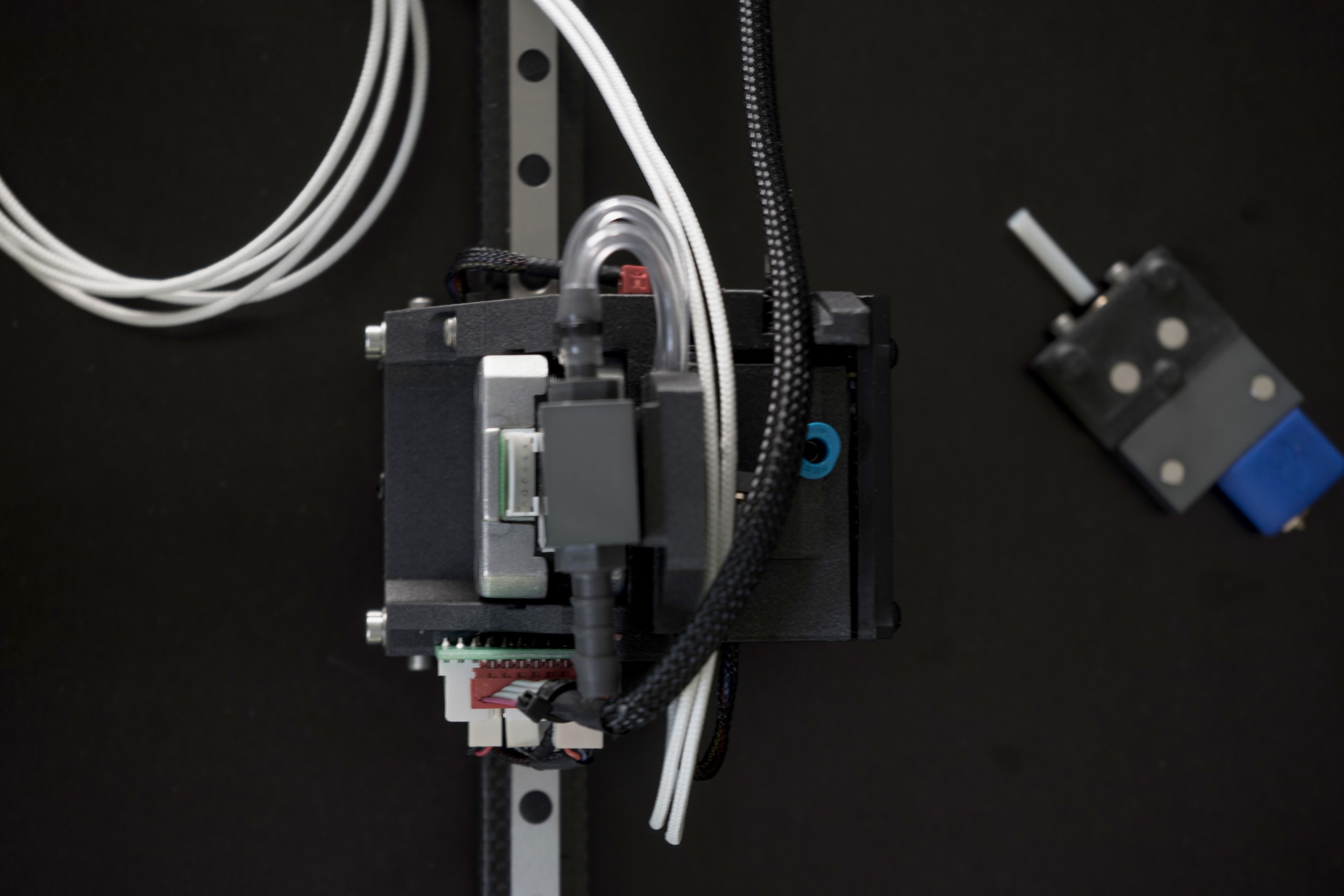
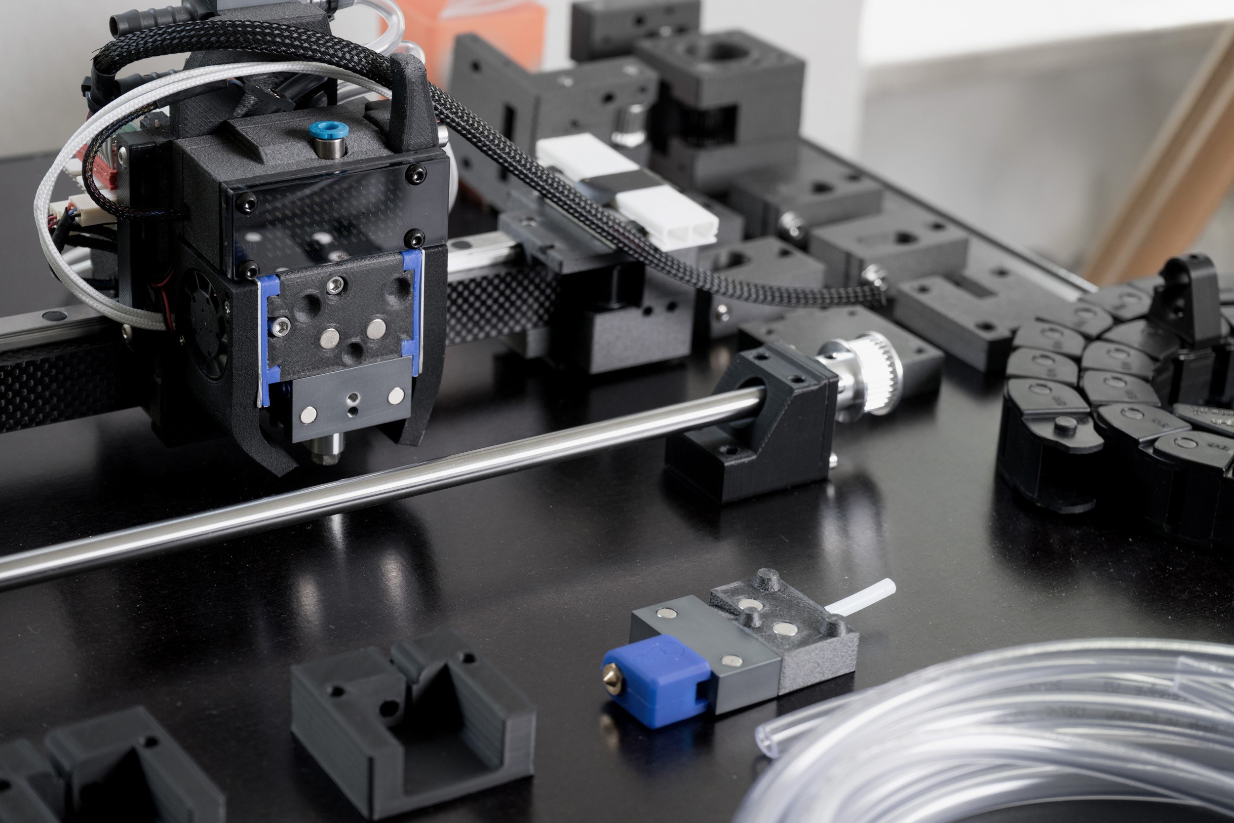
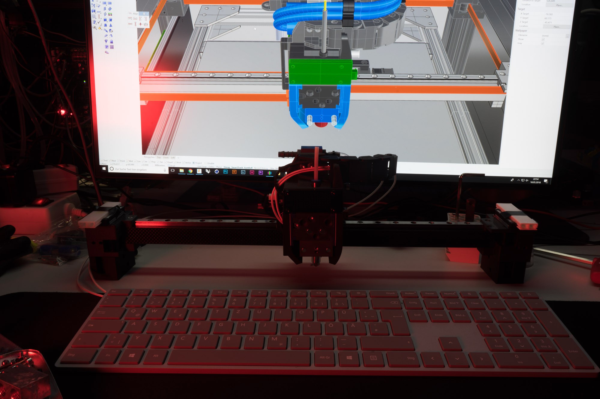
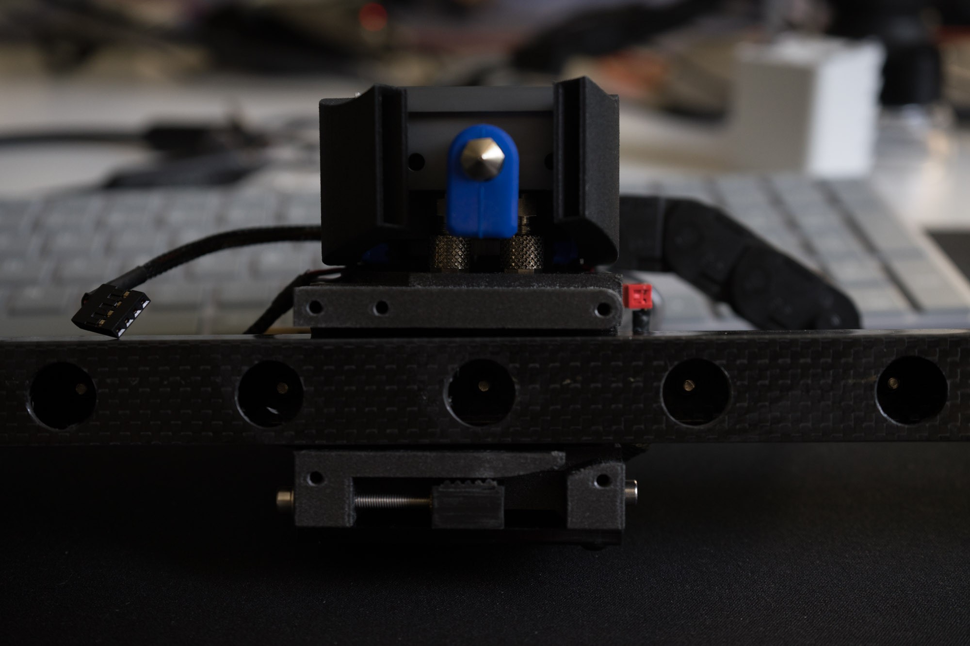
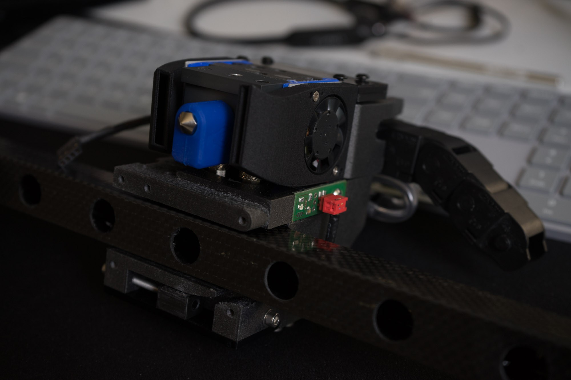
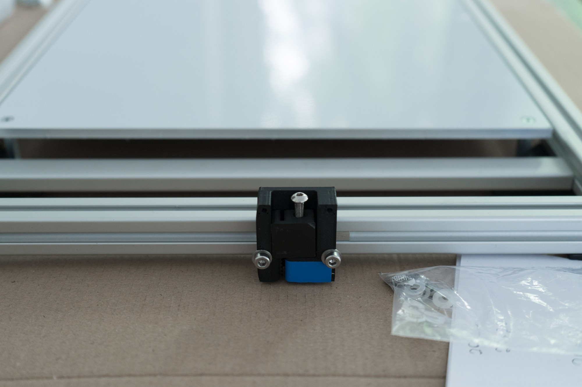
After upgrading the Blackbox with a tool changer, i had to find a way to calibrate the different hotends. The required precision cannot be achieved with mechanical measuring methods. I got inspired doing it optically by a forum post at 3d-druck-community.de Instead of taking a cheap USB microscope I used my mirrorless camera with the kit lens and macro rings. These rings are pretty bad for Makro photos because of the edge blur, but in this case, only the center has to be sharp. So macro rings will do fine for this job and the image quality is even superior to a cheap microscope.
The camera is mounted to the frame, that way you can use the Z-Axis to adjust the focus. I wrote a short script which changes the tool head and returns to a reference point in between.
Test routine G-Code
G21 ;metric values
G90 ;absolute positioning
G28 x; home X
G28 y; home Y
G28 Z; home Z
SET_PIN PIN=BEEPER_pin VALUE=120; short beep for start of the procedure
G4 P100
SET_PIN PIN=BEEPER_pin VALUE=0
G1 Y25 F5000; drive to save position
G1 X15.90 Y112.3 F5000; drive to calibration point
G1 Z224.50 F500; lift z-axis to desired height
T0; switch to tool 0
G1 Z224.50 F500
G1 X15.90 Y112.3 F5000; drive to calibration point
SET_PIN PIN=BEEPER_pin VALUE=80
G4 P2500
SET_PIN PIN=BEEPER_pin VALUE=0
G4 P500
T1; switch to tool 1
G1 Z224.50 F500
G1 X15.90 Y112.3 F5000; drive to calibration point
SET_PIN PIN=BEEPER_pin VALUE=80
G4 P2500
SET_PIN PIN=BEEPER_pin VALUE=0
G4 P500
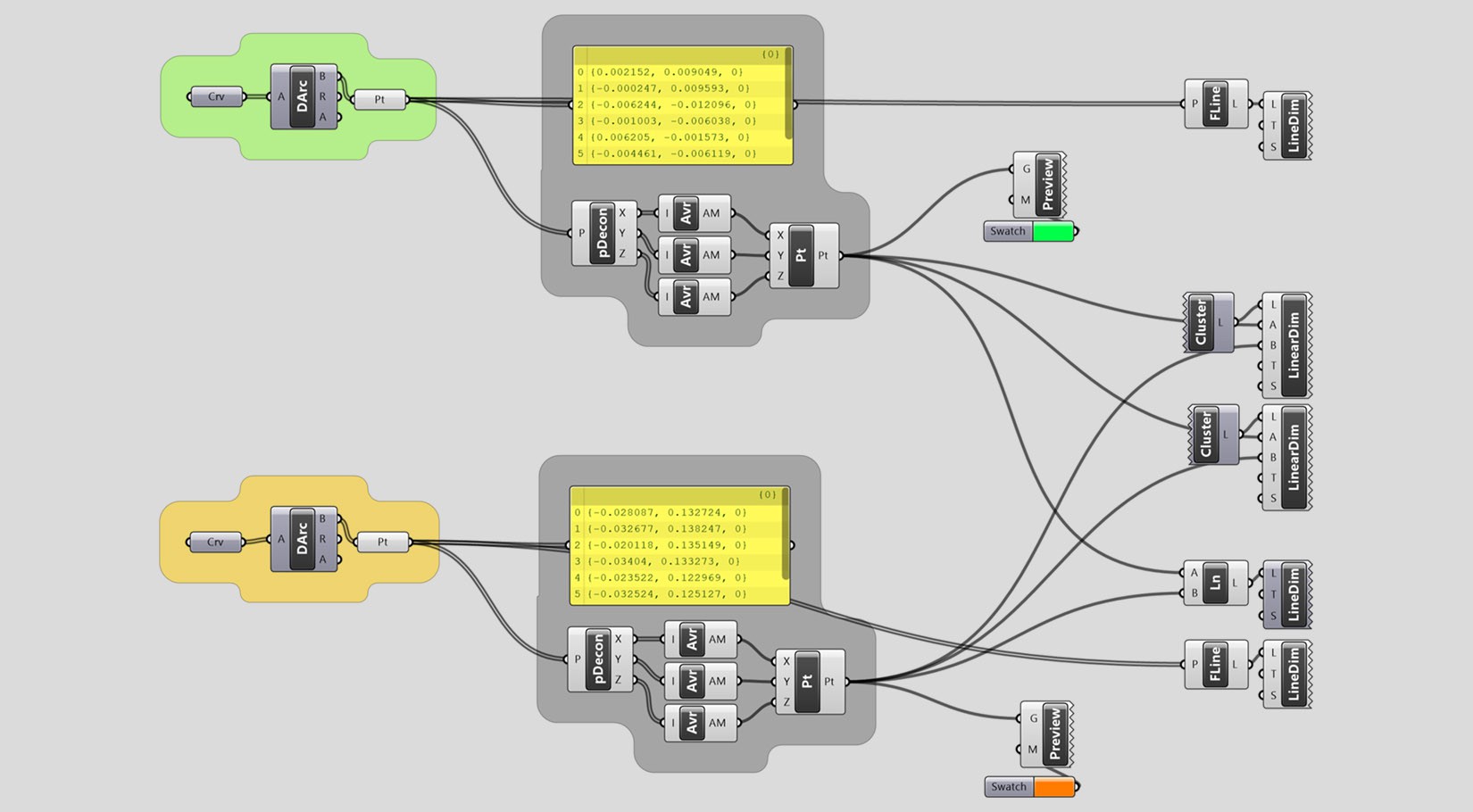
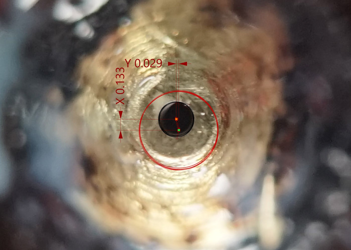
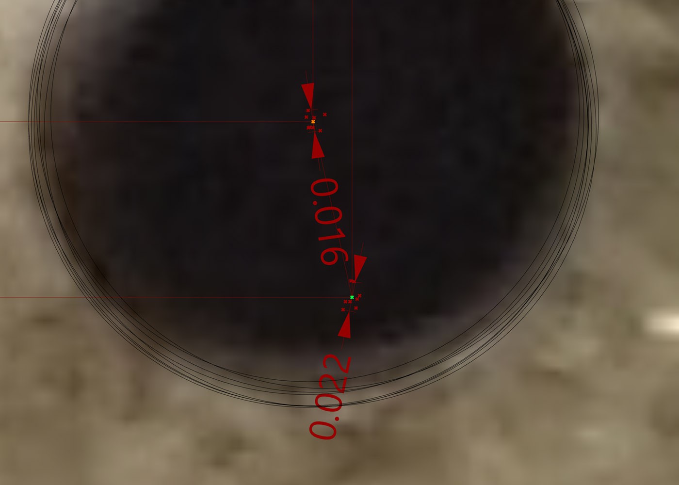
To simplify the analysis process, I wrote a simple grasshopper script. This script calculates the distance between the tools (toolhead offset). On the other hand, it calculates the deviation between extruder changes, which reveals how exact the tool change process actually is.
![]()
![]()
It calculates tool Offset
![]()
as well as deviation
Buttom Line
As the measurements show, the deviation during tool change is tiny at max. 22 microns. Especially concerning the 16 Mikron deviation of tool 01 (permanently mounted). The measurements from tool 0 to tool 1 differ by only 6 microns. I am very happy and confident about this result regarding further developments. The remaining variance is probably due to inadequate measuring methods and general printer tolerances. -
Big Github update!
06/11/2018 at 19:25 • 0 commentsI rolled out a big github Update today.
![]()
https://github.com/com9/blackbox
Changes where made on:
-Extruder (cleaned and simplified)
-Z Bearings Blocks -> changed to a 8mm rod
-Energy chain clips for the hoses and filament
-Lasercut boardplate (only suitable for Ultratronics, feel free to change it to your needs)
-Lasercut plate for Watercooling
-Fixture for PSU (Meanwell RSP-500-24)
-Fixture for C13 socket
-Awesome fan housing designed for SLS
-Z Belt fixture (still beta)
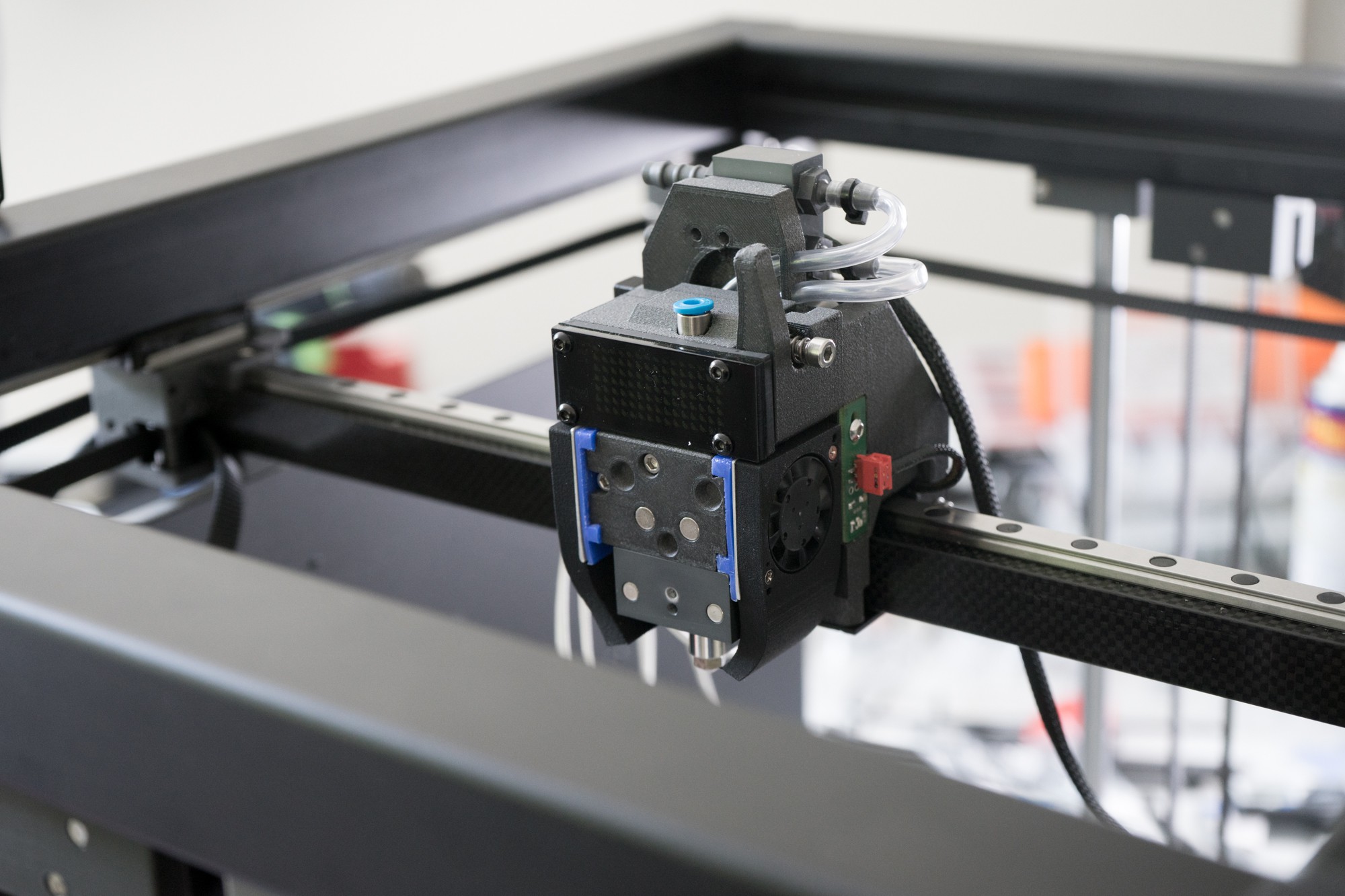
-Update on the toolhead and toolbank (still beta)
-changes on the z-guidance (still beta)
and much more!
I would change the Status of everything but the last three bits from "better wait a little before you buy something" to "if you know CAD and basic tooling, go ahead". The Z-Axis and toolchange are still a bit problematic and need some more working.
-
It´s Alive!
06/11/2018 at 11:50 • 0 commentsSorry for the sound fucked that up
-
Disassembly ☑ Assembly ☐
05/25/2018 at 13:41 • 0 commentsDisassembly was quick and easy, assembly turned out to be quite flawless also.
![]()
![]()
![]()
The XY Axis is in place but the belt i ordered is a few cm too short, dumb mistake, now im waiting for longer one.
![]()
![]()
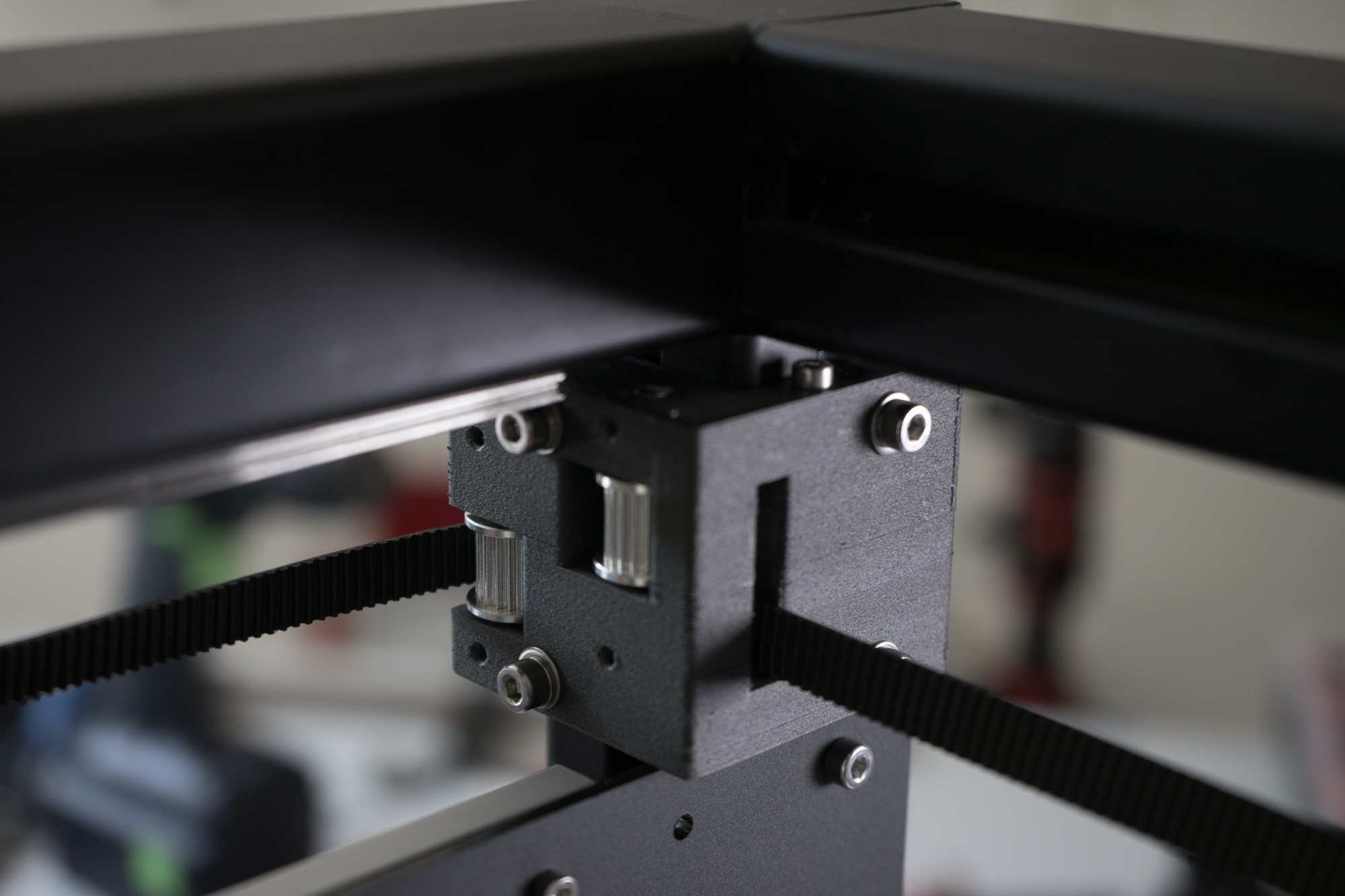
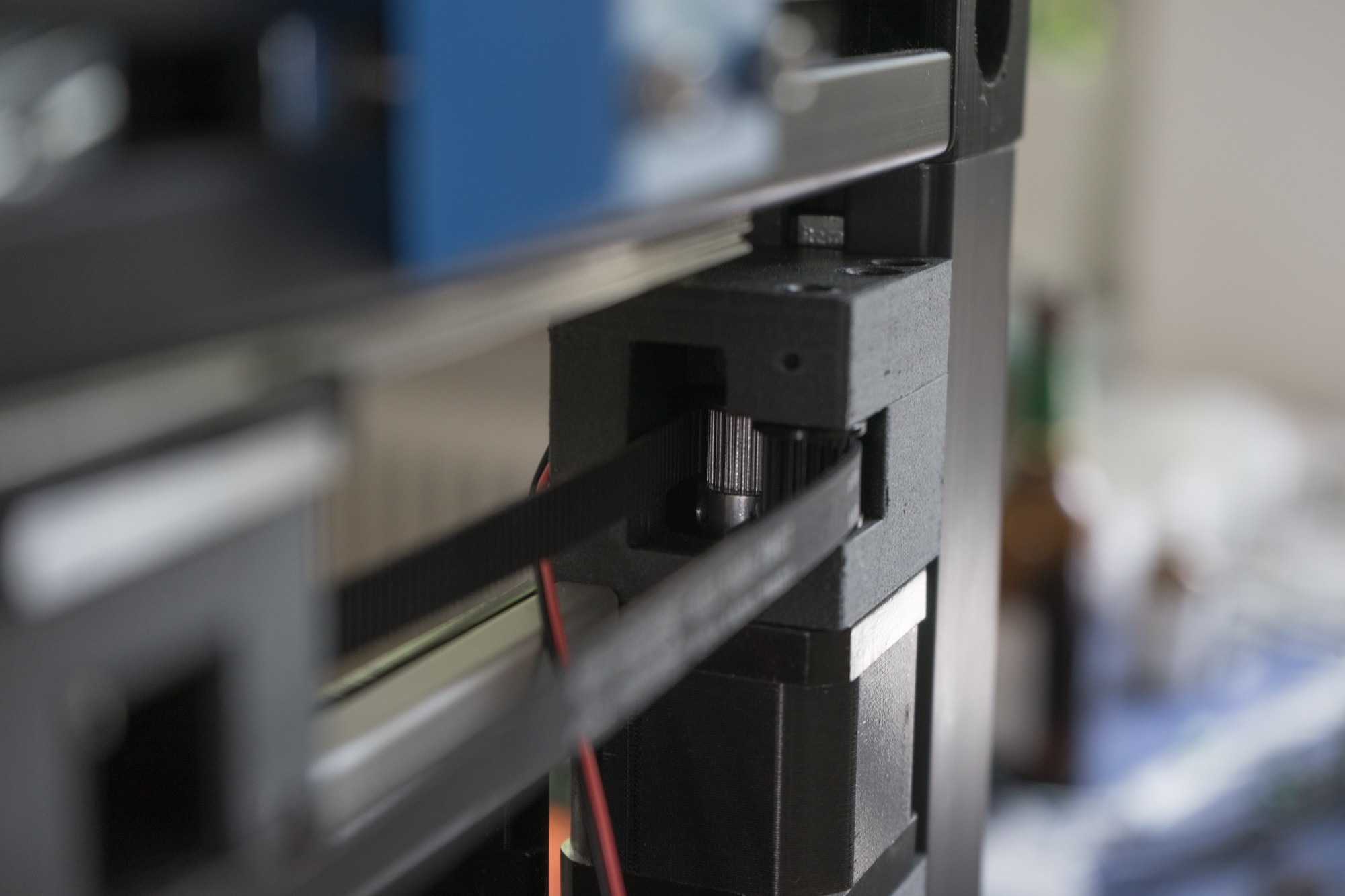
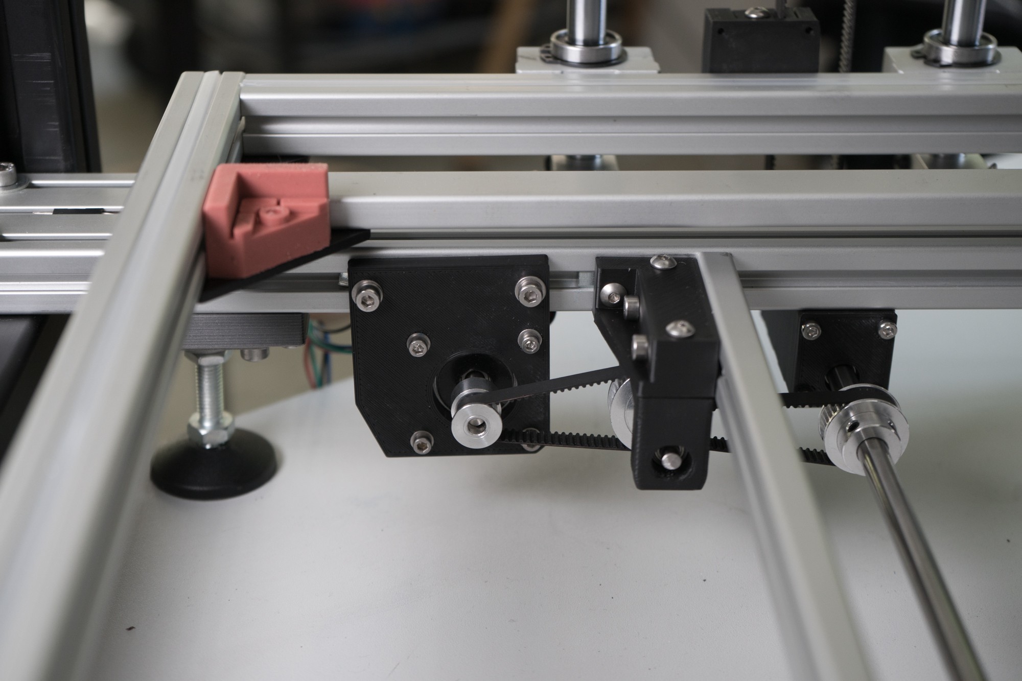
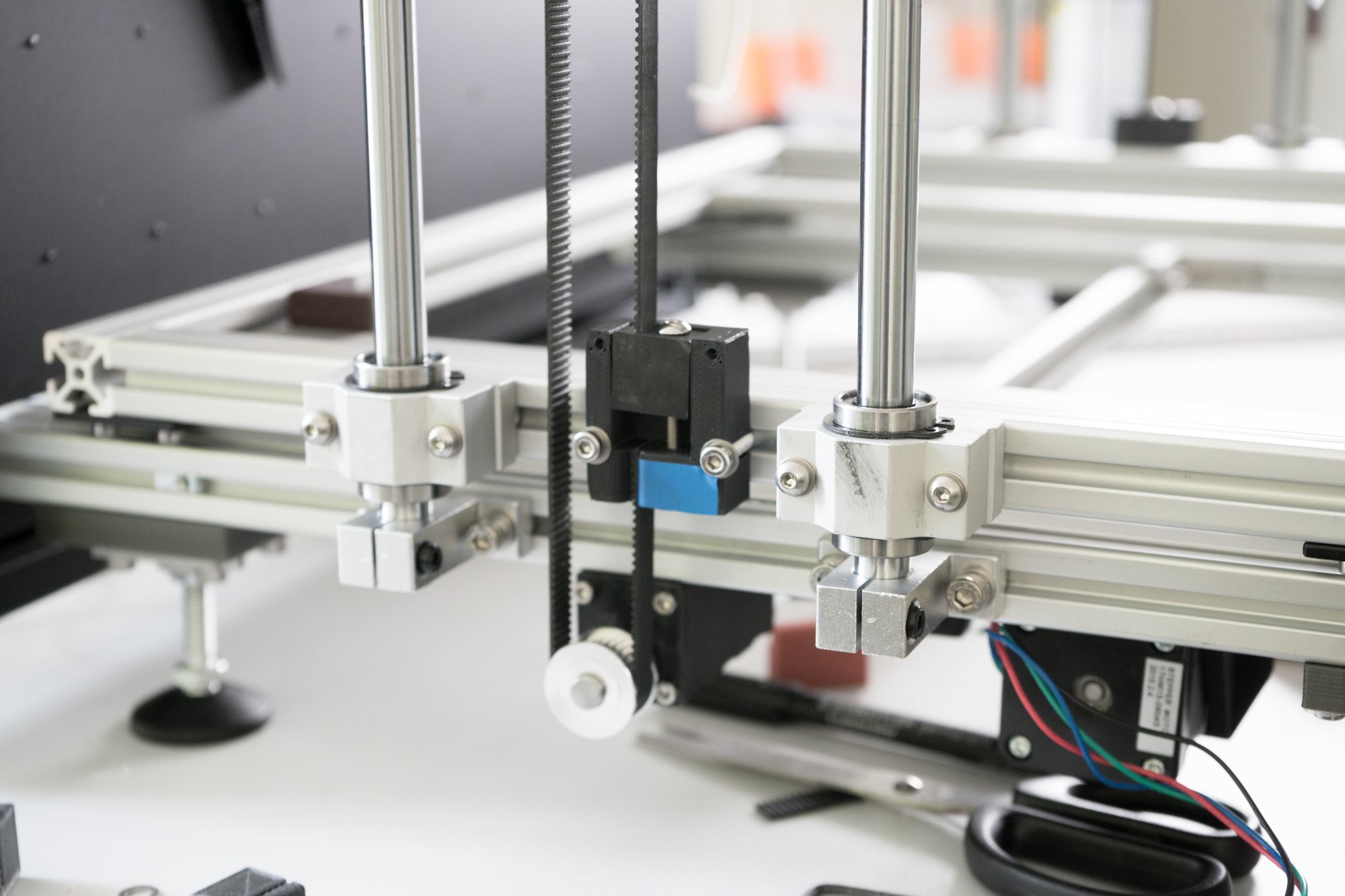
Belt reduction on the Z-Axis works really well. But it´s currently just a 1:5 reduction. Im waiting for a 64t pulley to achive 1:10 but i might need to add a tackle mechanism to achive a 1:20 reduction in order to hold the bed. Currently the bed is falling down pretty fast, i hope a 1:20 reduction will do the trick.
-
Everything set!
05/21/2018 at 16:06 • 0 comments![]()
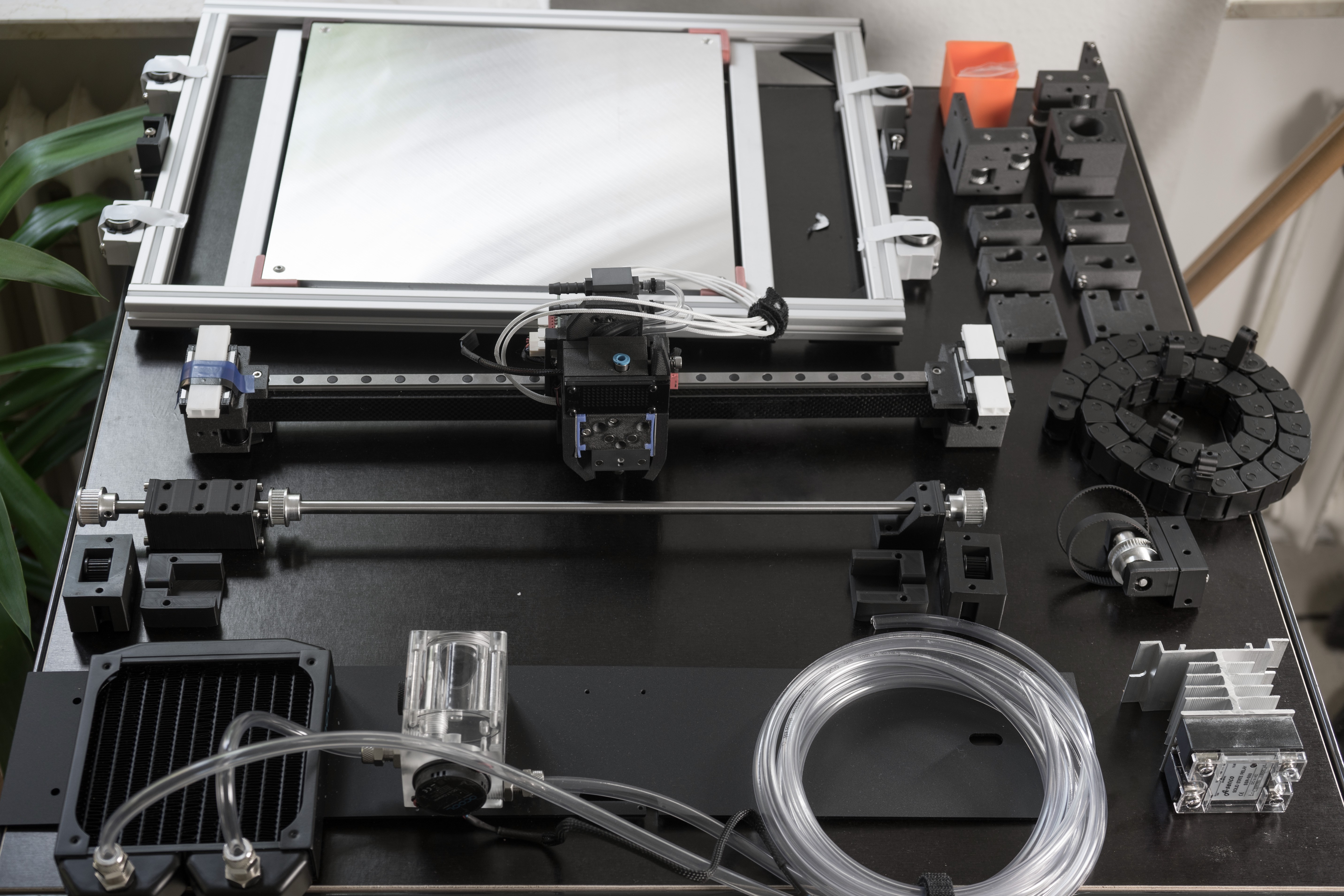
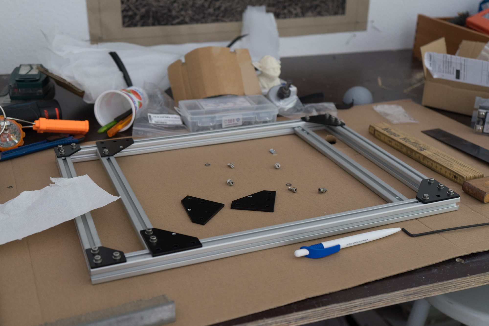
So i collected all parts and assembled the modules as far as possible. I began to disassemble the old Iteration today and if everything runs smoothly i should at least be able to assemble the XY-Axis today.
![]()
The XY-Axis is complete, you can see the new fancy SLS printed fanducts here, the just slide in. Cabling was a mess, i need to enlarge the cable channels big time.
![]()
![]()
![]()
![]()
-
Wiring done!
05/19/2018 at 00:23 • 0 comments![]()
![]()
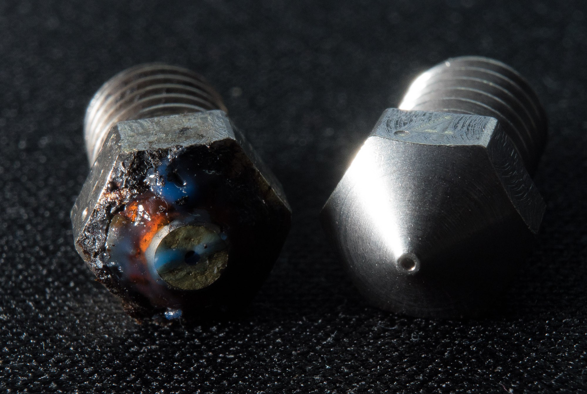
I got the XY-Axis assembly done after some seriously annoying problems. One major problem were tolerance issues which I have already mentioned. I found the cause by accident, i was switching to a .25 nozzle for some really problematic parts (flexible fan encoupling) and noticed the extreme wear of the nozzle. I was printing around three roles of carbon ABS until then. Although i was aware of the abrassive characteristics of carbon filament, i didn´t expected it to be THAT abrassive. I think we need to be careful to use claims like "wear resistance" like micro swiss does when you see something like this after just 3 roles.
![]()
But if you see these tolerances you may understand why i used carbon ABS. The tolerances i build with are very tight and the slightest warping would turn out to be a big problem. The X-Axis/Extruder assembly is the only part where this is REALLY crucial, the rest is fairly easy to Print.
![]()
The fans were surprisingly troubling too, in order to get them as compact as possible i decided to ditch the original aluminium housing for a custom sls printed housing/fanduct combination. The backside of the fan is held by flexible printed coupling. This results in a really slim and lighweight partcooling solution.
![]()
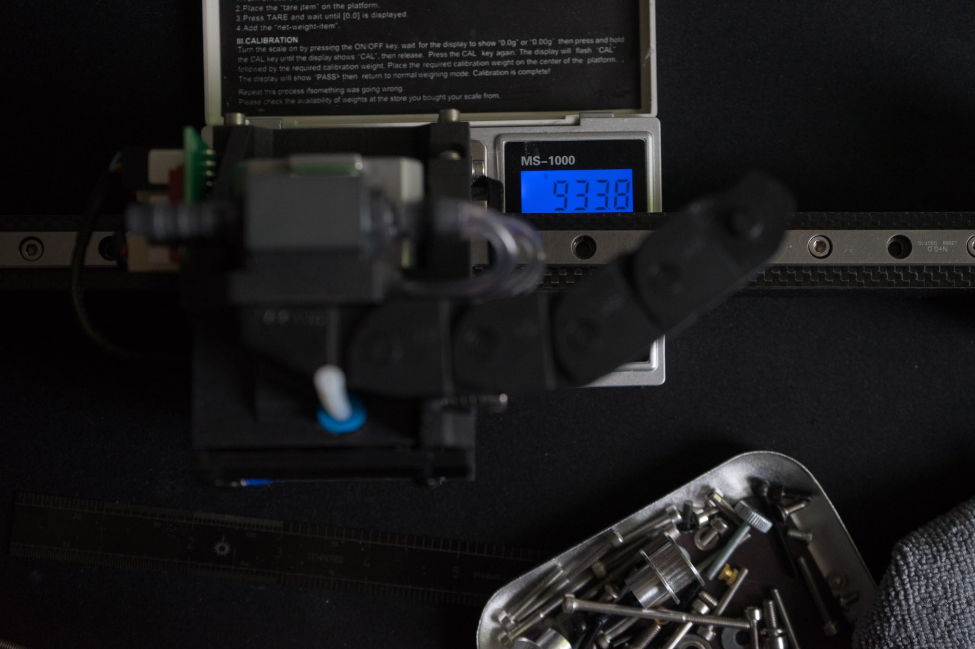
Total weight is around 930-950g, my goal was to stay below 1kg for the complete XY assembly and it looks like I'm gonna achieve that goal.
-
So close!
05/08/2018 at 19:06 • 0 commentsAfter several tolerance issues with my printer i was finally able to print the last iteration before the rebuild. The toolsystem looks good at first glance and i think i picked appropriate sized magnets. The new 8mm Z-Axis including heatbed is also ready for the big rebuild at the weekend. There is still an issue with the printed pulley, I still haven't managed to print a pulley that doesn't wobble.
Here is a small demo of the extruder toolchange mechanism
![]()
I used regular 2k epoxy glue for the Magnets. I had to buy way more magnets than necessary because they got big variance in tolerance.
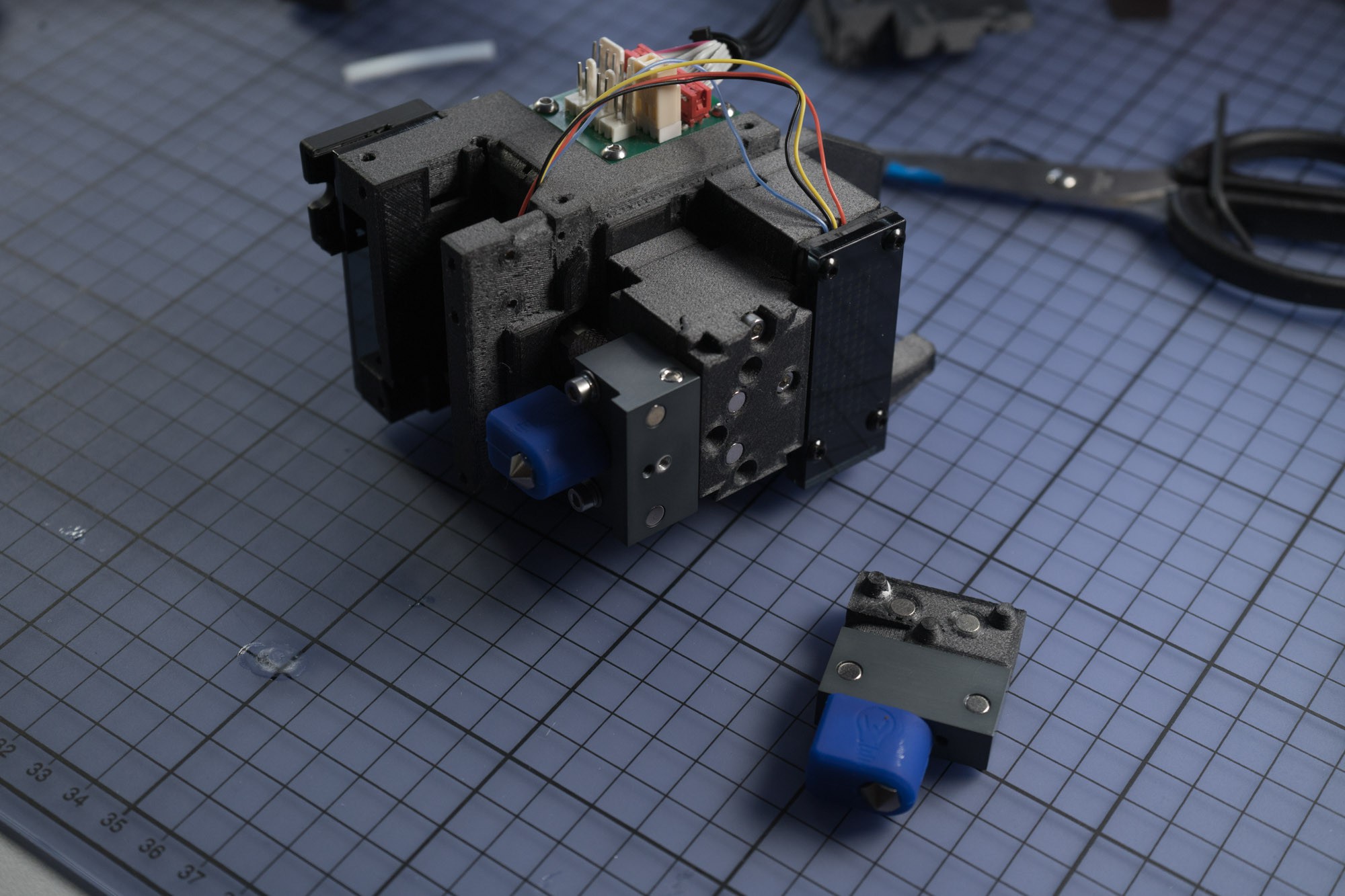
X-Axis weight: ca. 400g
Tool weight: ca. 36g
![]()
![]()
![]()
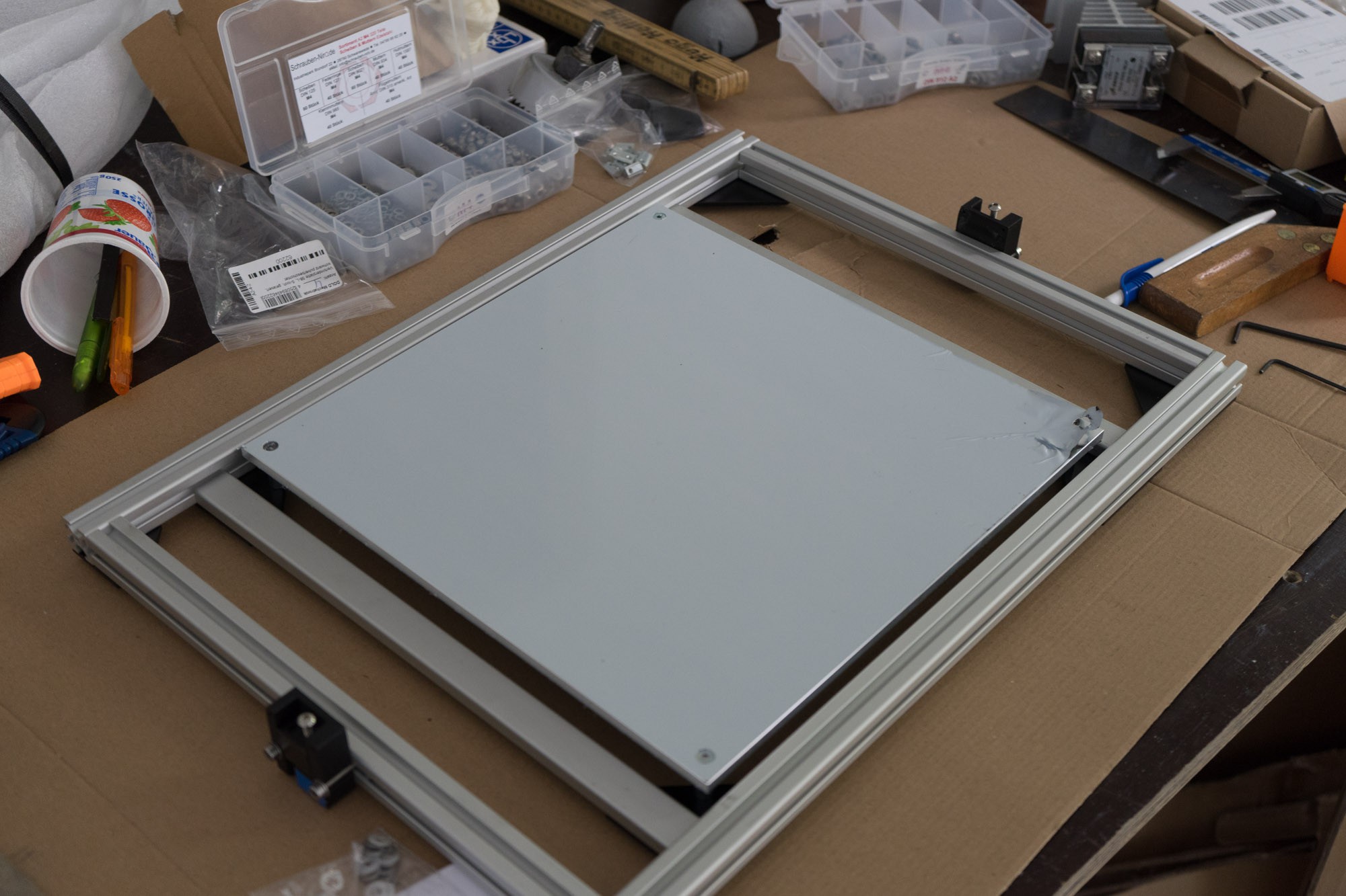
Belt tensioner on the Z-Axis, hopefully strong enough to hold this massive aluminium bed.
-
Team expansion
04/29/2018 at 13:35 • 0 commentsIm proud to announce that the Blackbox team has a new and ambitious supporter!
Let's welcome Prashanth Ray, experienced in 3D printing and currently researching on the topic of 3D Bioplotting at the Johns Hopkins University, USA.
Rays goals will be as follows:
"My goals in contributing to the project are
• Design and fabrication of a Multi-channel 3D bioprinting system containing
• Pneumatic extruder (Pneumatic control)
• Piston extruder (Mechanical Extrusion i.e Motor driving),
• Microneedle jet (Microdot i.e Pulse generation control)
• The 3D bioprinting system should be able to accept a variety of bio-materials to build composite hybrid scaffolds.
• Create an environment to maintain biocompatibility, mechanical properties etc.
I have few more ideas to work/modify and yes, keeping everything open-sourced."
Im thrilled to see Rays vision cumming true in the future!
-
collecting the last bits
04/28/2018 at 14:27 • 0 commentsZ-Axis:
I have finished the Z-axis and tested its functionality. The reduction works great but the 5mm rod seems to be undersized. On top of that i bought the wrong pulleys (6mm instead of 9mm) so i guess it´s a good excuse to size this axis up. While i think that 6.35mm is plenty the rods in this size are really hard to source so i guess i will use 8mm rod instead. That might be oversized but weight isn´t that important here.
![]()
![]()
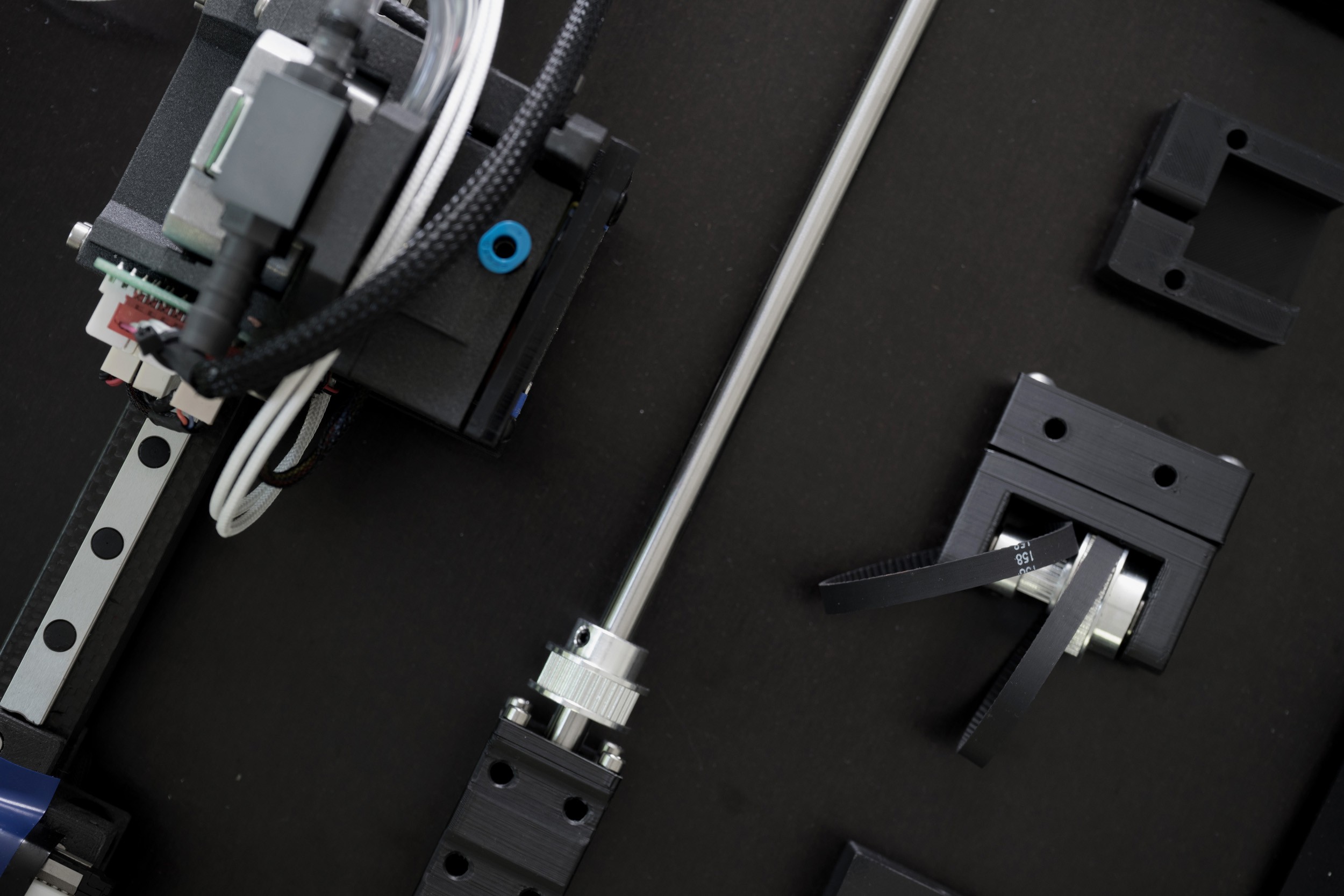
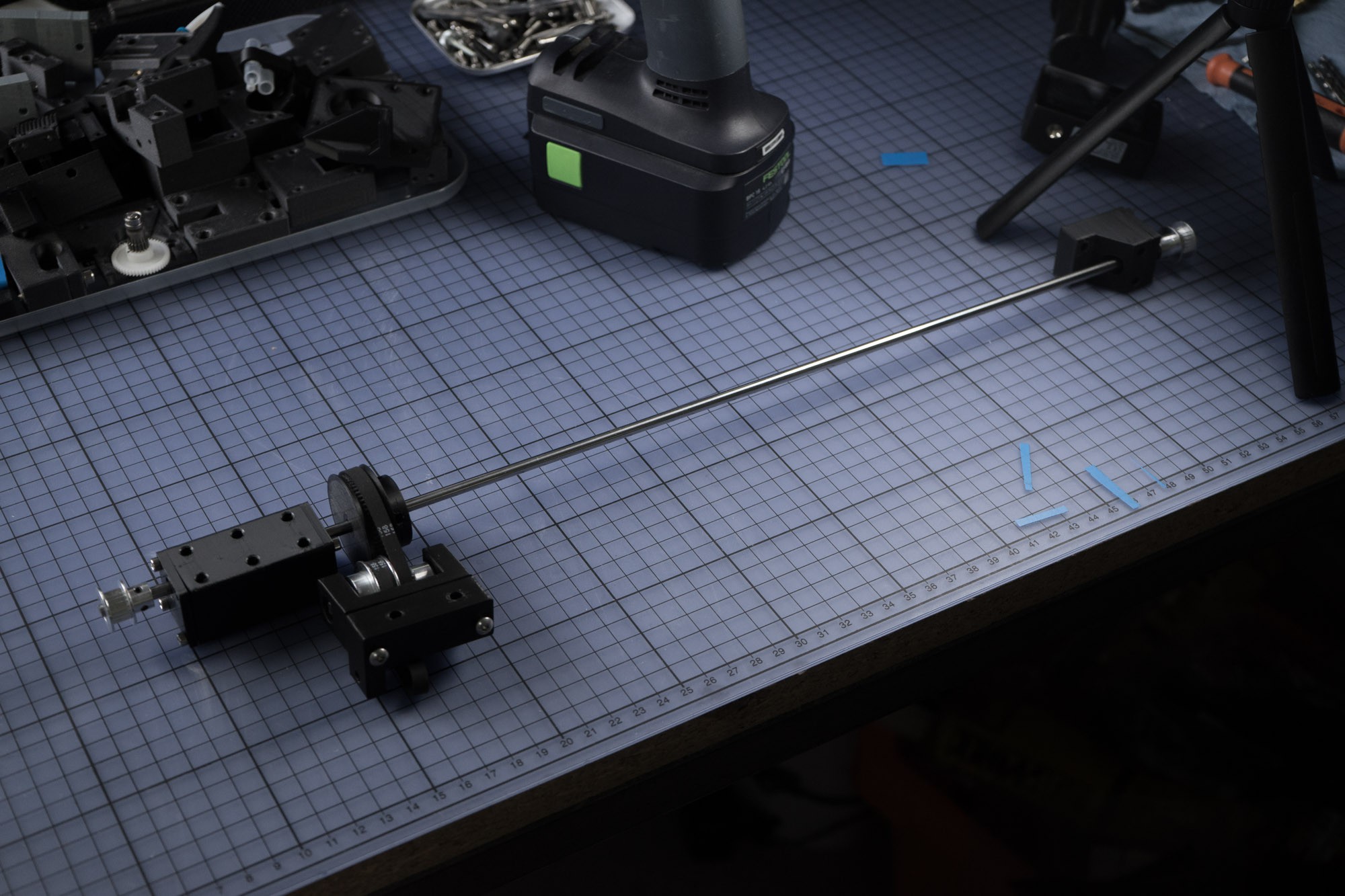
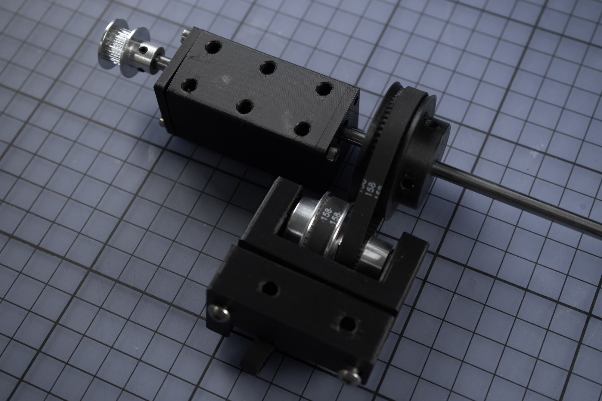
Above you can see the bearing pedestal, next to it the printed 64t pulley (unfortunately difficult to get in the EU) and below the pulley gearbox with belt tensioner.
![]()
Apart from that I am collecting all necessary parts together, as I only have one 3D Printer, all parts have to be together before the conversion can start.
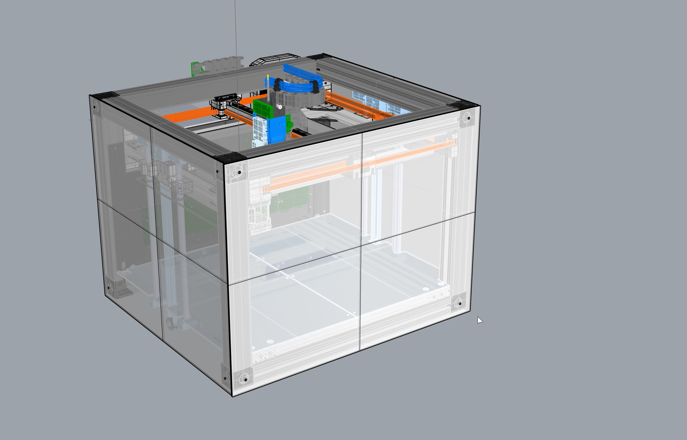
Blackbox - Tool Changing 3D Printer
high-end open-source printer with a water-cooled tool changer.
 Marc Schömann