Jean-François Duval
-
Managing timing: how to sequence tasks
09/04/2015 at 14:38 • 0 commentsIn many embedded applications timing is critical. Control loops have to be called at fixed intervals to guarantee stability and some data conversion have timings dependant on other software functions. One example, on the FlexSEA-Execute board, is the Delta Sigma ADC used for the Strain Gauge Amplifier: its conversion needs to be done when the I²C bus is in idle, otherwise the digital potentiometer are coupling noise in the sensitive analog circuit. We all know that a timer with interrupt can be used to generate precise timing, but we are also told that we should keep the interrupt service routine (ISR) code as short as possible. How can we get the best of all worlds?
Let’s say that we have a timer that calls an ISR every ms. The simplest ISR pseudo-code would look like:
timer_ISR()
{
    your_function_that_needs_to_be_called_at_1kHz();

    clear_ISR_flags();
}
You need to make sure that your_function_that_needs_to_be_called_at_1kHz() doesn’t take more than 1ms, and keep in mind that it will impact other timings in your code (if you have cycle-based delays like wait_ms(1) they will take longer to execute).
We can improve on that code by using a flag:
timer_ISR()
{
    timer_isr_flag = 1;	//Make sure to define that variable in your code
    clear_ISR_flags();
}
In your main while() loop:
while(1)
{
    if(timer_isr_flag == 1)
    {
        timer_isr_flag = 0;

        your_function_that_needs_to_be_called_at_1kHz();
    }

    //[…] other code […]
}
The timing will not be as precise depending on the other code running in the loop, but if you minimize this “other code” it can be more than good enough (as always, test this with an oscilloscope or a logic analyzer!)
Now, your program will probably require more than one function call. You can add calls, as long as their total execution time is less than the timer period:
while(1)
{
    if(timer_isr_flag == 1)
    {
        timer_isr_flag = 0;

        your_function_that_needs_to_be_called_at_1kHz();    //Function #1
        some_other_task();	                            //Function #2
        oh_and_I_also_need_to_do_this();                     //Function #3
    }

    //[…] other code […]
}
One thing that I do not like about this code is that if Function #1 takes longer, Functions #2 and #3 will be delayed. Also, how do you make it so #3 is called x µs after #1 without resorting to hard-coded delays? One option is to use more timers, and have one if(flag) call per timer. Another one, a better one in my book, is to divide that 1ms slot.
I’m using a 10kHz timer. Here’s the PSoC ISR code:
CY_ISR(isr_t1_Interrupt)
{
    /*  Place your Interrupt code here. */
    /* `#START isr_t1_Interrupt` */

	//Timer 1: 100us

	//Clear interrupt
	Timer_1_ReadStatusRegister();
	isr_t1_ClearPending();

	//All the timings are based on 100us slots
	//10 slots form the original 1ms timebase
	//'t1_time_share' is from 0 to 9, it controls the main FSM

	//Increment value, limits to 0-9
	t1_time_share++;
	t1_time_share %= 10;
	t1_new_value = 1;

	//Flag for the main code
	t1_100us_flag = 1;


    /* `#END` */
}
And here’s a simplified version of the main while(1) loop://Main loop while(1) { if(t1_new_value == 1) { //If the time share slot changed we run the timing FSM. Refer to //timing.xlsx for more details. 't1_new_value' updates at 10kHz, //each slot at 1kHz. t1_new_value = 0; //Timing FSM: switch(t1_time_share) { //Case 0: I2C case 0: i2c_time_share++; i2c_time_share %= 4; #ifdef USE_I2C_INT //Subdivided in 4 slots. switch(i2c_time_share) { //Case 0.0: Accelerometer case 0: #ifdef USE_IMU get_accel_xyz(); i2c_last_request = I2C_RQ_ACCEL; #endif //USE_IMU break; //Case 0.1: Gyroscope case 1: #ifdef USE_IMU get_gyro_xyz(); i2c_last_request = I2C_RQ_GYRO; #endif //USE_IMU break; //Case 0.2: Safety-Cop case 2: safety_cop_get_status(); i2c_last_request = I2C_RQ_SAFETY; break; //Case 0.3: Free case 3: //I2C RGB LED //minm_test_code(); update_minm_rgb(); break; default: break; } #endif //USE_I2C_INT break; //Case 1: case 1: break; //Case 2: case 2: break; //Case 3: Strain Gauge DelSig ADC, SAR ADC case 3: //Start a new conversion ADC_DelSig_1_StartConvert(); //Filter the previous results strain_filter_dma(); break; //[…] default: break; } //The code below is executed every 100us, after the previous slot. //Keep it short! //BEGIN - 10kHz Refresh //RS-485 Byte Input #ifdef USE_RS485 //get_uart_data(); //Now done via DMA if(data_ready_485_1) { data_ready_485_1 = 0; //Got new data in, try to decode cmd_ready_485_1 = unpack_payload_485_1(); } #endif //USE_RS485 //[…] } else { //Asynchronous code goes here. //WatchDog Clock (Safety-CoP) toggle_wdclk ^= 1; WDCLK_Write(toggle_wdclk); } }While the code above can look complex, it’s a big time saver. Once you implement that time share strategy you can freely edit your code without messing up with timings. It makes software updates and maintenance much easier! Please read the comments to understand the code, I believe they are explicit enough and more words wouldn’t make it clearer. If I’m wrong, ask any question in the comments. And, as always, look at the source code for the complete solution. -
Using DMA on a PSoC
08/26/2015 at 22:55 • 2 commentsIn this Project Log I’ll show you how I’m using DMA on a PSoC. My example will be based on the ADC, but it’s basically the same thing for all the peripherals. What’s DMA? From Wikipedia: “Direct memory access (DMA) is a feature of computer systems that allows certain hardware subsystems to access main system (RAM) memory independently of the central processing unit (CPU).”
The same page explains why this is useful: “Without DMA, when the CPU is using programmed input/output, it is typically fully occupied for the entire duration of the read or write operation, and is thus unavailable to perform other work. With DMA, the CPU first initiates the transfer, then it does other operations while the transfer is in progress, and it finally receives an interrupt from the DMA controller when the operation is done. This feature is useful at any time that the CPU cannot keep up with the rate of data transfer, or when the CPU needs to perform useful work while waiting for a relatively slow I/O data transfer.”
In Current controller: hardware I explained that I want my current sensor readings (done with the ADC) to be synchronized with the PWM. I wrote “Every 5th ADC sample a DMA interrupt is triggered”. Without DMA I would have had an interrupt every cycle (100kHz => 10µs). Let’s say that I need 25 instructions to enter the interrupt service routine (ISR), get the ADC reading, store it in an array, and return to the main program. One instruction on the 80MHz CPU takes 12.5ns; reading one value will take 312.5ns. 312.5ns every 10µs is 3.25% of my computing budget, and all I did was grab one reading!
To minimize the influence of noise I want to average multiple samples. In this case, a moving average of 5 samples will give me a refresh rate of 20kHz, perfect for this application. With the DMA controller taking care of getting the samples and placing them in an array I only need one ISR, thus requiring only 0.65% of my computing budget for this task.
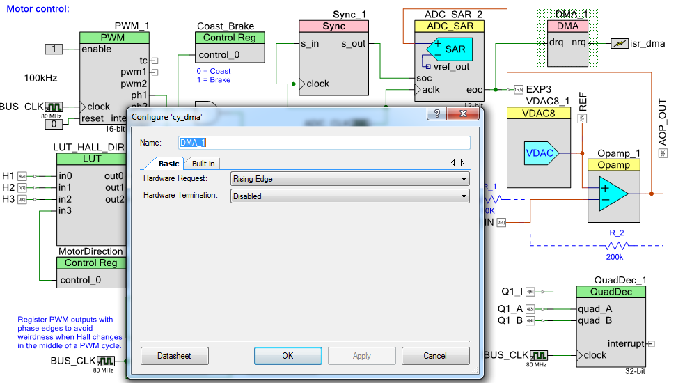
To get started I followed one video and one application note: PSoC Creator Tutorial: Working with DMA & AN52705 Getting Started with DMA.
![]()
I dragged a DMA component (DMA_1) and I linked it to the End of Conversion (eoc) output of my ADC. I selected Hardware Request = Rising Edge. The isr_dma component is used to call an interrupt when a DMA transfer is complete (in that case, after 5 samples have been acquired).
Use Tool => DMA Wizard to generate code. You can adjust your settings via the GUI, or you can keep the defaults and edit the code manually. Copy and paste the code in your project (I placed it in analog.c, the file that holds all the ADC conversion software). Here’s what I have:
//DMA for ADC SAR 2 transfers
//Triggers an ISR after 5 transfers
void adc_dma_config(void)
{
	/* Variable declarations for DMA_1 */
	/* Move these variable declarations to the top of the function */
	uint8 DMA_1_Chan;
	uint8 DMA_1_TD[1];

	/* DMA Configuration for DMA_1 */
	#define DMA_1_BYTES_PER_BURST 2
	#define DMA_1_REQUEST_PER_BURST 1
	#define DMA_1_SRC_BASE (CYDEV_PERIPH_BASE)
	#define DMA_1_DST_BASE (CYDEV_SRAM_BASE)
	DMA_1_Chan = DMA_1_DmaInitialize(DMA_1_BYTES_PER_BURST, DMA_1_REQUEST_PER_BURST,
	    HI16(DMA_1_SRC_BASE), HI16(DMA_1_DST_BASE));
	DMA_1_TD[0] = CyDmaTdAllocate();
	CyDmaTdSetConfiguration(DMA_1_TD[0], 10, DMA_1_TD[0], DMA_1__TD_TERMOUT_EN | TD_INC_DST_ADR);
	CyDmaTdSetAddress(DMA_1_TD[0], LO16((uint32)ADC_SAR_2_SAR_WRK0_PTR), LO16((uint32)adc_dma_array));
	CyDmaChSetInitialTd(DMA_1_Chan, DMA_1_TD[0]);
	CyDmaChEnable(DMA_1_Chan, 1);
}
adc_dma_config is called once, when I initialize all the peripherals. I’m using 2 bytes per burst because the 12bits ADC result is stored in 2 bytes. DMA_1_REQUEST_PER_BURST is 1: I want one transfer every time the drq line sees a rising edge. adc_dma_array is a buffer defined in the same file (int16 adc_dma_array[ADC1_BUF_LEN];); this is where your ADC values will be stored. Everything else is left at the default settings.
Adding the isr_dma component generated a file named isr_dma.c. The function called when a DMA transfer is complete is CY_ISR(isr_dma_Interrupt):
CY_ISR(isr_dma_Interrupt)
{
    /*  Place your Interrupt code here. */
    /* `#START isr_dma_Interrupt` */

	volatile int32 adc_sum = 0;
	volatile int32 adc_avg = 0;

	//Read last ADC value
	adc_sum = (int32)(adc_dma_array[0] + adc_dma_array[1] + adc_dma_array[2] + \
				adc_dma_array[3] + adc_dma_array[4]);
	adc_avg = (adc_sum / 5);

	ctrl.current.actual_val = (int32)(adc_avg - CURRENT_ZERO);
	//Used by the current controller, 0 centered.

	if((ctrl.active_ctrl == CTRL_CURRENT) || (ctrl.active_ctrl == CTRL_IMPEDANCE))
	{
		//Current controller
		motor_current_pid_2(ctrl.current.setpoint_val, ctrl.current.actual_val);
	}

    /* `#END` */
}
The comments should make it clear that all it does is average 5 values and call the motor current PID loop. (Calling a function in an interrupt is never recommended, but in that case I optimized motor_current_pid_2() to be as short as possible and I confirmed on the oscilloscope and signal analyser that everything was fine.)
Finally, here’s a scope capture. 1 is the 100kHz PWM (~30% duty cycle), 2 and 9 show the sampling of the ADC (it’s sampling when 9 is high), starting in the middle of the PWM and 8 is the DMA ISR. As you can see, the code is called once every 5 cycles.
![]()
-
What's new? Code, files & videos!
08/12/2015 at 21:57 • 0 commentsHello Makers!
With the Quarter Finals deadline coming it's time for a project update. I published most of the available information last May and June, just before graduating. I then left for a long bicycle camping trip; that's why nothing changed. Now that I'm back, I'm working full time as a Research Scientist in Biomechatronics and pushing FlexSEA further is one on my main projects. In the coming months I'll publish way more information about the system, including exoskeleton videos. Stay tuned! In the mean time, here's some new info:
- Introduction video
- You can now get a copy of the software projects and the hardware design files.
- In terms of system design document, please refer to my thesis. It contains extensive details about the hardware and the software. It's a great snapshot of the design as of May 2015.
- As far as licensing goes, the thesis is licensed under Creative Common Attribution-NonCommercial-ShareAlike (CC BY-NC-SA 2015) and the hardware files are Open Source Hardware.
- During my absence my colleague Luke Mooney used FlexSEA-Execute for his exoskeleton. Here's a short video of when he tested his force controller, using a strain gauge and the built-in amplifier of Execute 0.1.
- Do not hesitate to ask me questions about the system in the comments below!
- I'm looking for contributors for the project. Drop me a line if you are interested.
![]()
-
Design solutions – short answers
06/02/2015 at 11:33 • 0 commentsWhile all the details are available in the thesis, this section offers quick answers and solutions to all the issues identified in the introduction.
Lack of reliability: The issue of reliability is addressed at the board level with good design practice, documented unit tests and the use of safety mechanisms (such as ESD protected inputs). At the system level, the number of connections is reduced by embedding more features in the boards, and robust yet miniature connectors are used.
Lack of processing power, overloaded microcontroller: A dedicated microcontroller with a wide array of sensor inputs on the motor controller (FlexSEA-Execute) offloads the other computing units (FlexSEA-Mange and FlexSEA-Plan) from the intensive motor control functions. The microcontrollers used are also high performance. The optional embedded computer can be used for processor intensive applications.
"The original designer left" & "No electrical engineer in the team": Documentation must be exhaustive and accurate in order to fully enable the user. One of the graduation criteria is a user test. The system is designed in a modular way; the least intrusive way of using FlexSEA is to use a simple Linux terminal.
Slow communication peripherals: Closing control loops requires deterministic timings and fast refresh rates; it places a lot of stress on the board-to-board communication interfaces. By closing the critical control loops on FlexSEA-Execute we offload the communication interfaces. The FlexSEA-Manage board is also used as a bridge, communicating with FlexSEA-Plan via a high-speed SPI interface and communicating with other boards and peripherals via a variety of other communication protocols.
Can only support brushed motors: The Execute board is designed for brushless motors; it can inherently support brushed motors.
Can only support one motor: FlexSEA has been designed with scalability in mind. With its two serial interfaces, FlexSEA-Manage can support two FlexSEA-Execute without any bandwidth restrictions. More than one FlexSEA-Execute can be on each bus, the total bandwidth being divided between the boards.
Commercial motor driver has to be tricked into running a special control loop, no built in functionality: The user has full control over the hardware and the software of the motor driver. Any type of controller can be programmed in C and can run at high speed on the Execute board. The Expansion connector supports a wide variety of external sensors; they can all be used in control loops.
Power consumption: The power consumption of the embedded system can be high when an embedded computer is used. Better energy efficiency can be obtained by using a simpler computer; HD video peripherals, audio amplifiers and wired Ethernet connections are not required in wearable robotics applications. By maximizing the use of FlexSEA-Execute and FlexSEA-Manage, the FlexSEA-Plan computing requirements are lowered. A slower device can be used, or it can be placed in sleep mode between actions. Eliminating FlexSEA-Plan and programming the high-level algorithms on FlexSEA-Manage or FlexSEA-Execute can be extremely energy efficient.
Size, mechanical integration: The Execute and Manage boards were designed to be as small and light as possible. They have an integration level comparable to commercial products while having accessible connectors for inputs and outputs.
-
Introduction (why do we care?)
06/02/2015 at 11:31 • 0 commentsNote: this is copied from my thesis, please refer to the full document for references and additional graphics.
"Reinventing the wheel" is an idiom often associated with engineering and design. While innovators use the expression to describe a ground breaking solution or design, it mostly has a negative connotation. Engineers will be told not to reinvent the wheel when they are struggling with details or technicalities rather than focusing on the big picture, the problem worth solving. But what if that metaphorical wheel was indeed broken? Looking back at previous work in the field of exoskeletons and powered prostheses can be depressing for an embedded system designer. The wheel, in the form of the embedded electronics, is redesigned year after year, project after project, with no clear progression and many system redesigns. The 'big picture' problem is to give mobility to people that lost it, to augment able-bodied people, not to design electronics, but it is a critical component that can, in the worst case situation, invalidate a revolutionary artificial limb concept.
This thesis is not about the design of a novel wearable robotic device that contains an embedded system; it's purely about the design of the embedded system itself. The objective of the thesis is to advance an accessible and capable embedded system architecture that is useable across all wearable robotic research initiatives, eliminating the need to design a new embedded system for each and every research project. Ironically enough, once more, the goal is to redesign the wheel, but hopefully for the last time. Through a careful analysis of wearable robotic requirements across sensor, actuator and computational modalities, I will demonstrate in this thesis that an embedded system design can be achieved that is scalable across a plethora of wearable robotic research programs, and therefore will be used henceforth for more than one year in one project.
There are two main ways of designing electronic architectures for active wearable robotics: 1) microcontroller-based and 2) embedded computer-based. Figure 1 shows a typical microcontroller-based architecture with a single 80MHz processor [1]. Figure 2 shows an architecture based on an embedded computer, a Raspberry Pi running at 800MHz [2]. Commercial products are mostly microcontroller-based while research prototypes tend to favor systems with embedded computers [2][11][17].
Microcontroller
Embedded Computer
Pros
- Small form factor that can easily be adapted to different mechanical designs
- Low power
- Unit cost is low
- Low level software (C and/or ASM): processor efficient
- Quick design phase
- High-level software (C++, Python, Java, Matlab): ease of development
- Minimize the number of specialized skills required to modify the system
Cons
- Development (prototyping) cost can be higher
- Longer design phase
- Requires Electrical Engineering skills for the design, maintenance and modification
- Low level software (C and/or ASM): less portable, requires specialized skills
- High-level software (C++, Python, Java, Matlab): not processor efficient
- Higher power (less energy efficient)
- Relies on commercial parts (no control over the production and life cycle)
- Harder to modify
- Integration issues between different subsystems
- Sub optimal wiring
The two approaches have been used in a multitude of published wearable robotic systems, with various degrees of success. A few examples are described here [1][2][13][17]. Since the embedded system aspect of a design is considered a means to an end, documentation is considered unimportant and is usually scarce. Following the evolution of a wearable robotic design, one will read sentences such as "Developed a new embedded electronic system" without a clear justification as to why the previous design had to be abandoned rather than improved.
In all of the designs made in the MIT Biomechatronics Group over the last 11 years, only one project (AAKP, Agonist-Antagonist Active Knee Prosthesis [18]) used two actuators in one joint. Due to issues with the control electronics of previous prototypes, brushed DC motors (in lieu of brushless DC motors) were used, thus impacting the efficiency and mass of the prosthesis. When experiments were conducted with trans-femoral amputees wearing an active ankle-foot and an active knee the two joints were controlled independently, without an overarching high-level controller. Consequently, the lack of availability of an appropriate embedded system solution had a direct impact on the system design and performance [2][11].
After reading papers, grant reports and interviewing wearable robotic designers, the following list of general system problems and reasons justifying new designs was compiled:
- Lack of reliability
- Lack of processing power, overloaded microcontroller
- The original designer left the laboratory
- No electrical engineer on the team
- Slow communication peripherals
- Can only support brushed motors
- Can only support one motor
- Commercial motor driver has to be tricked into running a special control loop, no built in functionality
- Power consumption
- Size, mechanical integration issues
These problems are shared by many researchers in related fields such as humanoid robotics and wearable computers, therefore many designers and companies have attempted to design a unified embedded system that could be used in a broad range of projects. Commercially available modular hardware platforms include the Microsoft .NET Gadgeteer system, "an open-source toolkit for building small electronic devices using the .NET Micro Framework"[1] [3], the popular Arduino and its Shields ("Shields are boards that can be plugged on top of the Arduino PCB extending its capabilities."[2]), the BeagleBone Black embedded computer with the Capes and the Intel Edison with the Blocks[3]. SparkFun popularized the use of "breakout boards", minimalist circuit boards that simply prototyping. These products are now commonly integrated in academic research projects [2][3][9][11]. Custom embedded system designs have been published for wireless sensing [5], miniature mobile robots [6], and mechatronics education and teaching [7][8]. The common goals are to minimize the number of circuit redesigns and simplify prototyping [5].
The price to pay for modularity is often the increase of the number of circuit boards required for an application, and the increase of inter-board connections. Wearable robotics projects have different requirements than most pure robotics and wearable sensing projects. Safety and reliability are major issues, especially in powered prosthetic devices. Simplifying the devices by using a minimal number of circuit boards and by minimizing the number of interconnections helps with safety and reliability. The number of degrees of freedom is relatively small (compared to humanoid robotics), but the instantaneous power requirements are high [2][19]; a greater emphasis has to be placed on power electronics than on digital communication between the modules. The volume and the weight of the embedded system must be minimized because of their direct impact on the efficiency of devices attached to body extremities [19].
This thesis presents the design of a modular embedded system optimized for wearable robotic applications. A flexible architecture allows FlexSEA to be used in a wide variety of projects, with or without an embedded computer. All the safety features of commercial devices are included onboard, as well as all the typical sensors and output device interfaces required for wearable robotic applications. The highly integrated circuit board designs presented in the thesis minimize the weight of the embedded system, require a minimal amount of wired connections, and are proven to be easy to use by students. The design was evaluated by a user test and by multiple quantifiable metrics related to the electrical performance of the different circuit board, and of the system as a whole.
-
Current controller: software
06/01/2015 at 16:36 • 2 commentsMotor current sensing is an important feature for motor drivers. It is used as a safety feature to turn-off the PWM when excessive current is flowing through the driver, and to control the motor torque (torque is proportional to current). In this Project Log I'll detail how I implemented a high performance current controller on FlexSEA-Execute.
In Current controller: hardware I covered the hardware. Now that we can accurately measure current we can control it.
Every 5th ADC sample a DMA interrupt occurs. This code is called:
CY_ISR(isr_dma_Interrupt)
{
    /*  Place your Interrupt code here. */
    /* `#START isr_dma_Interrupt` */

	volatile int32 adc_sum = 0;
	volatile int32 adc_avg = 0;

	//Read last ADC value
	adc_sum = (int32)(adc_dma_array[0] + adc_dma_array[1] + adc_dma_array[2] + \
				adc_dma_array[3] + adc_dma_array[4]);
	adc_avg = (adc_sum / 5);

	ctrl.current.actual_val = (int32)(adc_avg - CURRENT_ZERO);
	//Used by the current controller, 0 centered.

	if((ctrl.active_ctrl == CTRL_CURRENT) || (ctrl.active_ctrl == CTRL_IMPEDANCE))
	{
		//Current controller
		motor_current_pid_2(ctrl.current.setpoint_val, ctrl.current.actual_val);
	}

    /* `#END` */
}
The last 5 values are averaged, and the current control function is called.
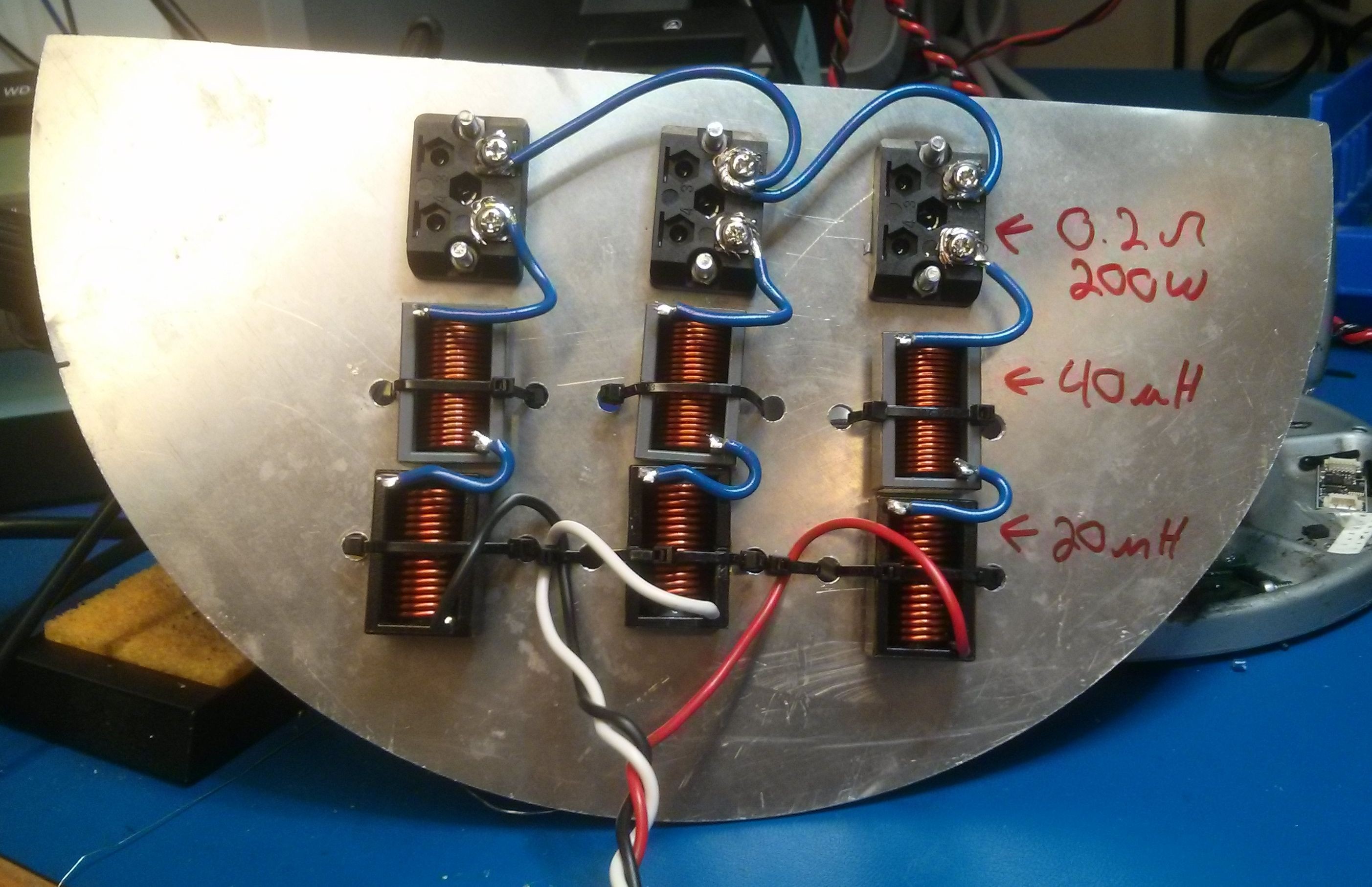
//PI Current controller #2: speed optimized
//'wanted_curr' & 'measured_curr' are centered at zero and are in the ±CURRENT_SPAN range
//The sign of 'wanted_curr' will change the rotation direction, not the polarity of the current (I have no control on this)
inline int32 motor_current_pid_2(int32 wanted_curr, int32 measured_curr)
{
	volatile int32 curr_p = 0, curr_i = 0;
	volatile int32 curr_pwm = 0;
	int32 sign = 0;
	int32 uint_wanted_curr = 0;
	int32 motor_current = 0;
	int32 shifted_measured_curr = 0;

	//Clip out of range values
	if(wanted_curr >= CURRENT_POS_LIMIT)
		wanted_curr = CURRENT_POS_LIMIT;
	if(wanted_curr <= CURRENT_NEG_LIMIT)
		wanted_curr = CURRENT_NEG_LIMIT;
	ctrl.current.setpoint_val = wanted_curr;

	//Sign extracted from wanted_curr:
	if(wanted_curr < 0)
	{
		sign = -1;
		MotorDirection_Control = 0;		//MotorDirection_Write(0);
		uint_wanted_curr = -wanted_curr;
	}
	else
	{
		sign = 1;
		MotorDirection_Control = 1;		//MotorDirection_Write(1);
		uint_wanted_curr = wanted_curr;
	}

	//At this point 'uint_wanted_curr' is always a positive value.
	//This is our setpoint.

	//From ADC value to motor current:
	shifted_measured_curr = measured_curr + CURRENT_ZERO;
	if(shifted_measured_curr <= CURRENT_ZERO)
	{
		//We are driving the motor (Q1 or Q3)
		motor_current = CURRENT_ZERO - shifted_measured_curr;
	}
	else
	{
		motor_current =  shifted_measured_curr - CURRENT_ZERO;
	}
	//ToDo above code seems complex for no valid reason

	//At this point 'motor_current' is always a positive value.
	//This is our measured value.

	//Error and integral of errors:
	ctrl.current.error = uint_wanted_curr - motor_current;					//Actual error
	ctrl.current.error_sum = ctrl.current.error_sum + ctrl.current.error;	//Cumulative error

	//Saturate cumulative error
	if(ctrl.current.error_sum >= MAX_CUMULATIVE_ERROR)
		ctrl.current.error_sum = MAX_CUMULATIVE_ERROR;
	if(ctrl.current.error_sum <= -MAX_CUMULATIVE_ERROR)
		ctrl.current.error_sum = -MAX_CUMULATIVE_ERROR;

	//Proportional term
	curr_p = (int) (ctrl.current.gain.I_KP * ctrl.current.error) / 100;
	//Integral term
	curr_i = (int)(ctrl.current.gain.I_KI * ctrl.current.error_sum) / 100;
	//Add differential term here if needed
	//In both cases we divide by 100 to get a finer gain adjustement w/ integer values.

	//Output
	curr_pwm = curr_p + curr_i;

	//Saturates PWM
	if(curr_pwm >= POS_PWM_LIMIT)
		curr_pwm = POS_PWM_LIMIT;
	if(curr_pwm <= 0)	//Should not happen
		curr_pwm = 0;

	//Apply PWM
	//motor_open_speed_2(curr_pwm, sign);
	//Integrated to avoid a function call and a double saturation:

	//Write duty cycle to PWM module (avoiding double function calls)
	curr_pwm = PWM1DC(curr_pwm);
	CY_SET_REG16(PWM_1_COMPARE1_LSB_PTR, (uint16)curr_pwm);					//PWM_1_WriteCompare1((uint16)curr_pwm);
	CY_SET_REG16(PWM_1_COMPARE2_LSB_PTR, (uint16)(PWM2DC(curr_pwm)));	//PWM_1_WriteCompare2((uint16)((curr_pwm >> 1) + 1));
	//Compare 2 can't be 0 or the ADC won't trigger => that's why I'm adding 1

	return ctrl.current.error;
}
To avoid destroying expensive Maxon motors during the calibration phase a test bench was designed and assembled. In the present configuration the phase to phase specs are 120µH and 0.4Ω. The power resistors are rated for 200W. The larger inductance makes it safer for the power electronics under test. The current ripple will be half of the Maxon's.
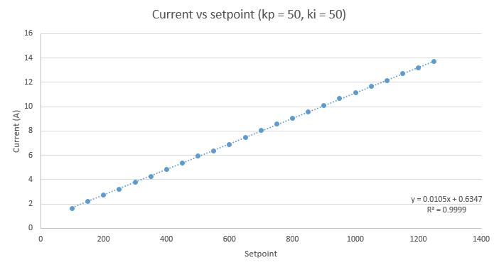
The first test I did was static: set a current setpoint, measure the real current, plot.![]()
![]()
The sense resistor is 5mΩ, the analog gain is 20 and the ADC is 12bits over 5V. The theoretical current resolution is 12.2mA/bit. With a setpoint of 500, the expected current is 6.1A and the measured value is 5.94A. The absolute error is only 2.6% and the transfer function is extremely linear, great!
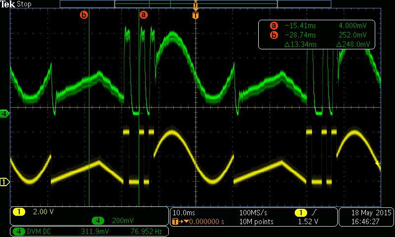
I had to make sure that the dynamics of my controller were fast enough to be used on robotic devices. To test that, I created an arbitrary waveform (a mix of triangles, sinusoids and square waves with abrupt transitions). I outputted the current controller setpoint on a DAC (yellow) and I measured the current flowing in one phase with a current probe (green). As you can see on the picture below, my current controller has no problem tracking the waveform.
![]()
-
Current controller: hardware
06/01/2015 at 15:33 • 0 commentsMotor current sensing is an important feature for motor drivers. It is used as a safety feature to turn-off the PWM when excessive current is flowing through the driver, and to control the motor torque (torque is proportional to current). In this Project Log I'll detail how I implemented a high performance current controller on FlexSEA-Execute.
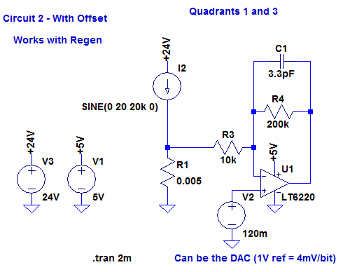
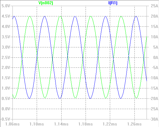
The programmable analog blocks of the PSoC can be used to design a small, low-cost motor current sensor. I started by doing an LTSpice simulation of the complete analog circuit:
![]()
![]()
0A will give me an output of 2.5V (half my ADC voltage supply), 20A = 0.5V and -20A = 4.5V. I kept a safety margin of 0.5V near each rail to account for component tolerances and to make sure that a small overcurrent wouldn't saturate the sensor.
In the PSoC we use one operational amplifier, one DAC and one analog multiplexer. In "real hardware", we only need one shunt resistor per bridge (), two resistors and one capacitor.
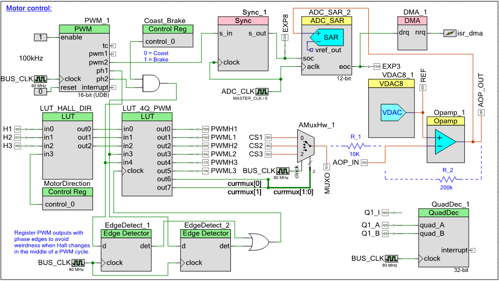
In PSoC hardware, the current sensing is strongly linked to all the motor control circuits: the following schematic has a lot of components!
![]()
TLDR: with hardware, we amplify the current measurement, sample it at the PWM mid-point, convert it and trigger an interrupt every 5 samples.
I'll explain how the BLDC driver works in a different log; for now, let's focus on the current controller portion. PWM_1 is the 100kHz PWM signal used to control the motor speed. The pwm2 output will always go high at the mid-point of the active ON time (ie if my period is 10us and my duty-cycle is 50%, pwm will be initially off, then it will turn on at the 5us mark. pwm2 will become active at the 7.5us mark.) We use this rising edge to trigger ADC_SAR_2 (Sync_1 makes sure that the clocks are synchonized, otherwise we could miss pulses). The signal that is measured comes from Opamp_1; that's the opamp you saw on the LTSpice simulation. As you can see, an analog multiplexer (AmuxHw_1) is used to select one of the 3 sense resistors as the input of the amplifier. That selection is done in the LUT_4Q_PWM look-up table. We only read the leg that has its low-side switch turned on. Every 5th ADC sample a DMA interrupt is triggered. It calls the software current PI controller, for an effective refresh rate of 20kHz.
In Current controller: software I cover the software aspect, and show you scope screen captures.
-
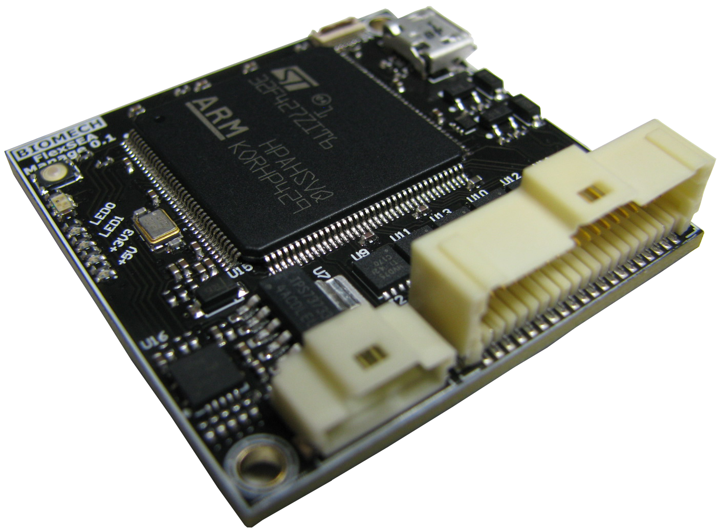
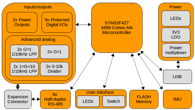
FlexSEA-Manage
05/12/2015 at 17:45 • 0 commentsFlexSEA-Manage is a polyvalent circuit that can have a wide range of usages depending on the system architecture. In the simplest system designs, it will act as a communication protocol translator, allowing Plan and Execute to communicate. When multiple FlexSEA-Execute are used, it routes packets, and can manage communication timings. It can be used to add extra sensors and output devices to the system. In systems that do not require the computing power of an embedded computer, Manage can host the high-level state machines.
![]()
The following figure presents the hardware diagram of FlexSEA-Manage 0.1. In orange are the schematic sheets and in grey are the sub-circuits present on certain sheets.
![]()
Electrical specifications
Supply voltage (V)
5V in (from Plan or USB), on-board 3V3 regulator
Current (mA)
90mA
Microcontroller
Reference
STM32F427ZIT6
Special features
Floating-point co-processor can be software enabled.
CPU/RAM/IOs/Package
180MHz ARM Cortex-M4, 2MB FLASH, USB
Software / IDE
Eclipse C/C++, GNU Tools for ARM Embedded Processors (arm-none-eabi-gcc), OpenOCD GDB.
Serial interfaces
Type
2x [half-duplex, asynchronous full-duplex or synchronous full-duplex RS-485]
Bandwidth
2-10Mbps
Type
Full-duplex SPI
Bandwidth
20+ Mbps
Onboard USB
Full-Speed (FS) / High-Speed (HS)
Peripherals / features
FLASH memory
128Mbits
IMU
6-axis (3x accelerometer, 3x gyroscope)
Power output
2x 24V 1A high-side switches
LEDs
2x green, 1x RGB
Switches
1x user input switch
IO connector
Molex PicoClasp 40 positions, SMD 1mm pitch
External peripherals
IOs available
17, shared with functions below
Digital IOs
Up to 9, protected
Analog inputs
8x 12-bit SAR with special functions (filters, amplifiers, dividers, …)
Serial
I²C, SPI, USART
Dimensions (mm)
X (mm)
40
Y (mm)
40
Z (mm)
11.5
PCB technology
Layers
4
Copper
1Oz
Trace/space/via
5/5 mils trace/space, 8/20 mils vias
Technology
Standard
Assembly
Double-sided
-
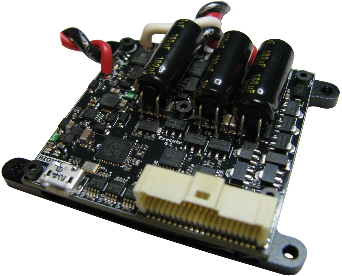
FlexSEA-Execute 0.1: Advanced motion controller
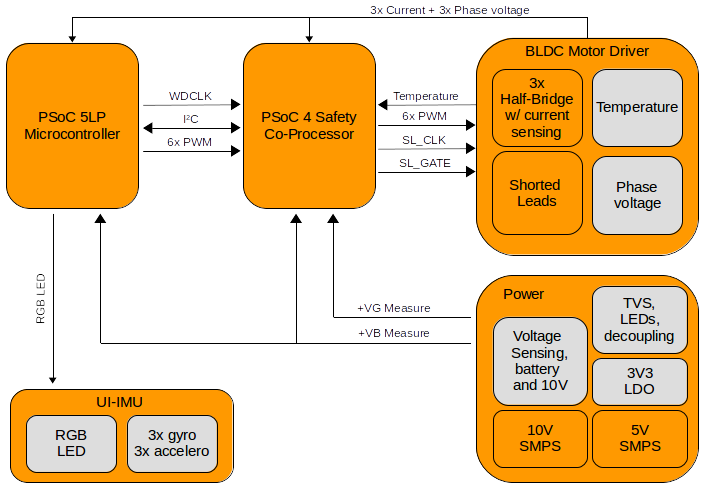
05/12/2015 at 17:43 • 0 commentsAt its core, the FlexSEA-Execute board is a BLDC motor driver. It is specialized for robotic and prosthetic applications. The high level design goals were to maximize the system integration (small physical dimensions, large number of integrated peripherals and interfaces, support for external input and output devices), allow fast communication and networkability via the use of a fast multi-drop communication interface, and have built-in safety features. The design went through three major revisions; this document focuses on the last generation (FlexSEA-Execute 0.1) (for more details (and pictures) about the previous designs, refer to The evolution of FlexSEA prototypes.)
![]()
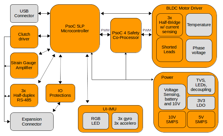
The next figure presents the logical organization of the FlexSEA-Execute 0.1 board. In orange are the schematic sheets and in grey are the sub-circuits present on certain sheets.
![]()
The safety system is extremely important. The next diagram highlights the safety related features:![]()
Electrical specifications
Supply voltage (V)
15-24V
Motor current (A)
20A Continuous
Intermediate supply
10V 500mA SMPS
Logic supply
5V 500mA SMPS
Motor
Type
3-phase brushless (BLDC)
Sensor(s)
Hall effect, optical encoder
Commutation
Block, Sinusoidal, FOC
PWM
12 bits 20kHz, 10 bits 78kHz or 9.65 bits 100kHz
Microcontroller
Reference
PSoC 5LP - CY8C5888AXI-LP096
Special features
Programmable analog and digital blocks
CPU/RAM/IOs/Package
80MHz ARM Cortex-M3, 256KB RAM, 62 IOs, TQFP
Software / IDE
PSoC Creator 3.1, mix of C (ARM GCC 4.7.3) and graphical programming.
Co-processor(s)
PSoC 4 - CY8C4245LQI-483
Serial interface
Type
3x Half-Duplex RS-485 (can be full-duplex synchronous)
Bandwidth
2-10Mbps
Onboard USB
Full-Speed (FS) 12 Mbps
Current sensing
Hardware
0.005Ω resistor
Software / control
20kHz Proportional-Integral controller
Safety features
Overvoltage
TVS will clamp at 36V
Overcurrent
Software protection
Locked rotor
Hardware - lead shorting circuit
Motor temperature
Hardware measurement
Board temperature
CPU + bridge temperature reading
Clutch
Variable voltage, 8-bits PWM, 400mA
Strain gauge amplifier
Dual stage, 500 < G < 10000, high CMRR
IO connector
Molex PicoClasp 40 positions, SMD 1mm pitch
External peripherals
IOs available
12
Digital IOs
Up to 12
Analog inputs
Up to 8 (12-bit SAR, 8-20-bits Sigma Delta)
Serial
I²C, SPI, UART
Other
1 optical encoder (A/B/I), 1 Hall effect encoder (3 pins)
Dimensions (mm)
X (mm)
49
Y (mm)
49
Z (mm)
From 12 to 15mm depending on capacitors
PCB technology
Layers
6
Copper
1 Oz
Trace/space/via
5/5 mils trace/space, 8/20 mils blind vias
Assembly
Double-sided
Other
6-axis IMU, RGB LED
-
FlexSEA Overview
05/12/2015 at 17:37 • 0 commentsThere are two main ways of designing electronic architectures for active wearable robotics: 1) microcontroller-based and 2) embedded computer-based. Commercial products are mostly microcontroller-based while research prototypes tend to favor systems with embedded computers.
Microcontroller
Embedded Computer
Pros
- Small form factor that can easily be adapted to different mechanical designs
- Low power
- Unit cost is low
- Low level software (C and/or ASM): processor efficient
- Quick design phase
- High-level software (C++, Python, Java, Matlab): ease of development
- Minimize the number of specialized skills required to modify the system
Cons
- Development (prototyping) cost can be higher
- Longer design phase
- Requires Electrical Engineering skills for the design, maintenance and modification
- Low level software (C and/or ASM): less portable, requires specialized skills
- High-level software (C++, Python, Java, Matlab): not processor efficient
- Higher power (less energy efficient)
- Relies on commercial parts (no control over the production and life cycle)
- Harder to modify
- Integration issues between different subsystems
- Sub optimal wiring
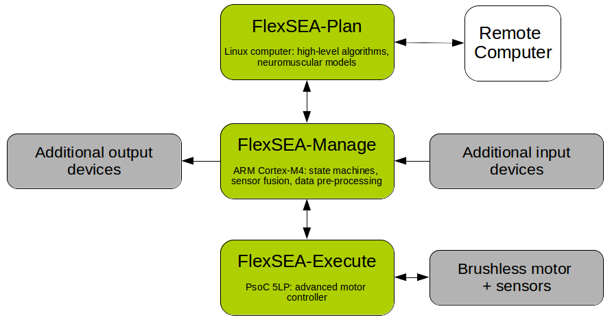
FlexSEA combines the two major embedded system design approaches. Commercial products are usually microcontroller-based. They can have small form factors, low power requirements and a low unit cost but programming them, adding sensors and motors or networking multiple circuits together requires specialized skills or extensive circuit and system redesign. On the other end, research prototypes often use embedded computers as the main computing element. The design phase is short and high-level software can be used but the mechanical integration is problematic, the power consumption is high, interconnections lack reliability and there is no clear path towards commercialization. FlexSEA combines the two approaches, keeping only the best features.
FlexSEA-Plan![]()
FlexSEA-Plan is an embedded computer used for high-level computing. It boasts a powerful processor and can run an operating system such as Linux. Developing code on this platform is similar to the regular (i.e. non-embedded) software development process. High-level languages such as Python can be used, saving experimental data is as simple as writing to a text file and interacting with the system can be done via USB or WiFi. FlexSEA-Plan should be used when ease of development is important, and when complex algorithms and control schemes require significant computing power.
FlexSEA-ManageFlexSEA-Manage is used for mid-level computing tasks. It serves as an interface between FlexSEA-Plan and FlexSEA-Execute: communication protocols translation, data routing, time-sharing. It has an Expansion connector that can interface with a wide variety of input and output devices. Data acquisition, processing, and aggregation can be done on this board, thus unloading FlexSEA-Plan from these simple tasks. For applications that do not require intensive computing, FlexSEA-Plan can be taken out of the system and FlexSEA-Manage can host the high-level state machines.
FlexSEA-ExecuteFlexSEA-Execute is an advanced brushless motor driver. Wearable robotics applications require different control loops than the typical position and current controllers found on commercial drives. FlexSEA-Execute has onboard sensors (6-axis IMU, temperature, voltage, current), interfaces (strain gauge amplifier), processing power and connectivity to make it possible to close most control loops onboard. It is well suited for the series elastic actuators (SEA) commonly used in prostheses.
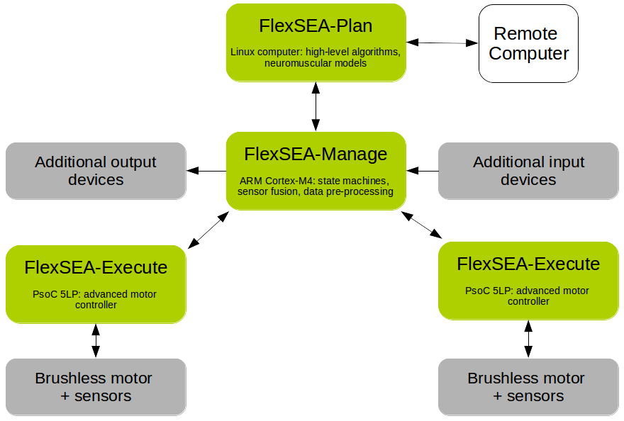
Two degree of freedom projects can be made with 1 Plan, 1 Manage and 2 Execute:
![]()
FlexSEA: Wearable robotics toolkit
OSHW+OSS to enable the next generation of powered prosthetic limbs and exoskeletons. Let’s make humans faster/better/stronger!