I'm still waiting for my 12E to arrive but in the meantime I'm using the 01 and from playing around with it I have a few suggestions:
- I think you mentioned this already but another pin for 3.3V input as part of JP2 would be great. Using the Vcc pin of the FTDI header might not always be convenient and using the rails seems a bit strange ;)
- I use CP2102 USB/serial converters whose signal level is 3.3V but their onboard 3.3V regulator can't handle the required current. Therefore, a solder jumper to to run the input voltage from the FTDI header either directly to Vcc or to the regulator on this PCB would allow for 5V input through that header.
- The pull-up and LED+resistor on GPIO0 always connect Vcc and ground. The leakage in my case wasn't really a problem but due to the LED I used I had to chose a lower value for the resistor (otherwise it was barely visible) which lead to GPIO0 only being biased to 1.7V. I'm curious, what's the bias voltage on your boards? Everything seemed to work but I think it'd be better to tie the LED to Vcc just to make sure the bias doesn't depend on the choice of LED.
I got away with my FTDI programmer that has a jumper to switch the VCC between 3.3V and 5V, that I simply took of and powered the board with USB instead. But yes, I have to add those jumpers :)
Whenever the ESP board resets, I've noticed that the LED is shining dim. That makes a lot of sense, I didn't see that before because of my "exploded" design in EAGLE. So when GPIO0 is HIGH or LOW my blue LED works fine, but when it is an input, it gets weird. I have no idea about the bias voltage.
How about... a quadruped robot? :P I think you can control 8 servos with the esp8266 directly, so you could make something like #Katka, a mammalian robot easily.
I've been meaning to ask if you'd like to trade one of your boards for a panel of #Breadboard Widgets but obviously I had to wait for the micro USB version ;)
 davedarko
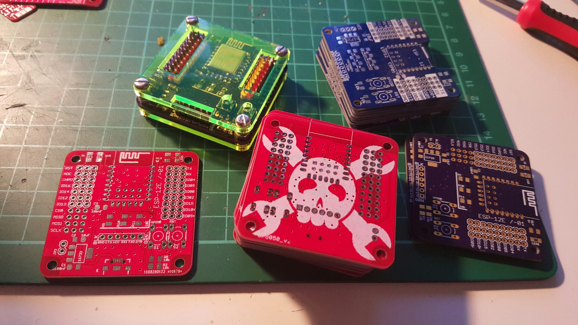
Discussions
Become a Hackaday.io Member
Create an account to leave a comment. Already have an account? Log In.
Thanks Dave!
I'm still waiting for my 12E to arrive but in the meantime I'm using the 01 and from playing around with it I have a few suggestions:
- I think you mentioned this already but another pin for 3.3V input as part of JP2 would be great. Using the Vcc pin of the FTDI header might not always be convenient and using the rails seems a bit strange ;)
- I use CP2102 USB/serial converters whose signal level is 3.3V but their onboard 3.3V regulator can't handle the required current. Therefore, a solder jumper to to run the input voltage from the FTDI header either directly to Vcc or to the regulator on this PCB would allow for 5V input through that header.
- The pull-up and LED+resistor on GPIO0 always connect Vcc and ground. The leakage in my case wasn't really a problem but due to the LED I used I had to chose a lower value for the resistor (otherwise it was barely visible) which lead to GPIO0 only being biased to 1.7V. I'm curious, what's the bias voltage on your boards? Everything seemed to work but I think it'd be better to tie the LED to Vcc just to make sure the bias doesn't depend on the choice of LED.
Are you sure? yes | no
Uhh nice!
I got away with my FTDI programmer that has a jumper to switch the VCC between 3.3V and 5V, that I simply took of and powered the board with USB instead. But yes, I have to add those jumpers :)
Whenever the ESP board resets, I've noticed that the LED is shining dim. That makes a lot of sense, I didn't see that before because of my "exploded" design in EAGLE. So when GPIO0 is HIGH or LOW my blue LED works fine, but when it is an input, it gets weird. I have no idea about the bias voltage.
Are you sure? yes | no
I feel kind of silly that I only thought of doing this after I read your comment
... seems like the simplest thing now ;)
Are you sure? yes | no
How about... a quadruped robot? :P I think you can control 8 servos with the esp8266 directly, so you could make something like #Katka, a mammalian robot easily.
Are you sure? yes | no
too bad the rails are 3.3V :( I should add ground and another voltage rail on the other side. But yes, your robots are on my todo list :)
Are you sure? yes | no
Katka runs on 3.7V just fine...
Are you sure? yes | no
I should have left the 3rd pin on the voltage regulator IOs, would have been easier to attach a lipo this way.
Are you sure? yes | no
I've been meaning to ask if you'd like to trade one of your boards for a panel of #Breadboard Widgets but obviously I had to wait for the micro USB version ;)
Are you sure? yes | no
that is the micro version ;)
Are you sure? yes | no
I meant I've been waiting until now. So are you interested in trading?
Are you sure? yes | no
sure :)
Are you sure? yes | no