-
Let There Be Source
05/29/2015 at 11:01 • 8 commentsOkay, I've created some github projects and pushed my source so far. This is only what I have now, but I intend to make it usable.
First up: https://github.com/henryk/milight-reverse-engineering simply contains all the little tools and some of the notes I developed while doing the actual reverse engineering. I don't believe that it's useful to anyone, but you never know. This is totally undocumented and unsupported, and in some cases has commented-out functionality from different phases of the process. YMMV.
Then there's my currently most stable code in https://github.com/henryk/openbeacon-ng/tree/openmili (in firmware/nRF51/pca10031-openmili). This is actually the openbeacon-ng project by my friend Milosch Meriac, but it does have a build system for the nRF51 that is not as full-on retarded as the official Nordic SDK, and also allows for easier code sharing. At some point this should somehow move into the actual project described next.
Finally, there's the OpenMili project: https://github.com/henryk/openmili. This is supposed to be the actual project that people want to use. I have a grand mental plan, but there's only the Arduino proof-of-concept code in there as of now.
The idea is to have proper layers of abstraction and build upon them, allowing mix-and-match as needed. Some of the comments on this http://hackaday.io project indicated that they were/are working along similiar lines, but do have a real PL1167 (or compatible). So the middle layer will be a virtual PL1167 abstraction, that can either shell out to a real PL1167 (I may need help here, since I don't have one to test on) or an emulation on a Nordic chip. As I've said before I want support for both the nRF51[48]22 and nRF24L01(+) chips on the layer below that. Above that would be a thin shell for Mi-Light 2.4GHz frames so that a simple serial protocol will allow to make useful use of the hardware from a host application. Then the first primary goal is to have a host application that fully replaces a Mi-Light Wi-Fi gateway, possibly with slightly better timing, and, most importantly, configurable IDs. (First idea: open multiple UDP ports, each port will send with a different ID; Second idea: also open TCP ports for reliable communication.)
Then, far off in the future I see the possibility of a more advanced firmware implementation with vastly improved timing and features: interleaving multiple commands to different bulbs when sending, maybe performing color animations autonomously, receiving and reporting commands sent by other remotes when idle.
-
Command And Control
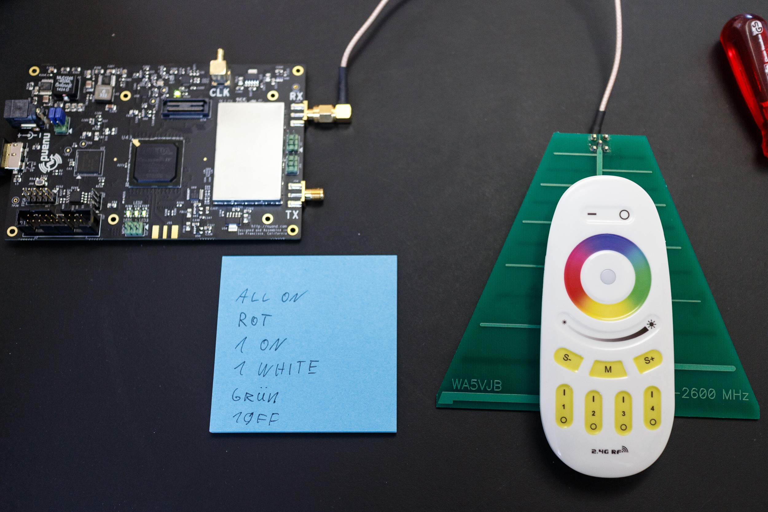
05/27/2015 at 11:04 • 7 commentsWhen entering a short test sequence on my remote this is what my receiver displays (a dot means an exact repetition of the previous packet):
All on:
07 B0 F2 EA 35 90 01 B9 AC F9 ..........................
07 B0 F2 EA 35 90 00 B9 74 E0 ..

Color red:
07 B0 F2 EA 04 90 0F BA 6E 01
07 B0 F2 EA 04 90 0F BB E7 10
07 B0 F2 EA 04 90 0F BC 58 64
07 B0 F2 EA 04 90 0F BD D1 75
07 B0 F2 EA 04 90 0F BE 4A 47
07 B0 F2 EA 04 90 0F BF C3 56
07 B0 F2 EA 04 90 0F C0 B3 DD
07 B0 F2 EA 04 90 0F C1 3A CC
07 B0 F2 EA 04 90 0F C2 A1 FE
07 B0 F2 EA 04 90 0F C3 28 EF
07 B0 F2 EA 04 90 0F C4 97 9B
07 B0 F2 EA 04 90 0F C5 1E 8A
07 B0 F2 EA 04 90 0F C6 85 B8
07 B0 F2 EA 04 90 0F C7 0C A9
07 B0 F2 EA 04 90 0F C8 FB 51
07 B0 F2 EA 04 90 0F C9 72 40
07 B0 F2 EA 04 90 0F CA E9 72
07 B0 F2 EA 04 90 0F CB 60 63
07 B0 F2 EA 04 90 0F CC DF 17
07 B0 F2 EA 04 90 0F CD 56 06
07 B0 F2 EA 04 90 0F CE CD 34
07 B0 F2 EA 04 90 0F CF 44 25
07 B0 F2 EA 04 90 00 CF 8C A6 ............................

Group 1 on:
07 B0 F2 EA 04 91 03 D0 4E 3E .............................
07 B0 F2 EA 04 91 03 D1 C7 2F .............................

Group 1 white:
07 B0 F2 EA 04 91 13 D2 CD 88 .............................
07 B0 F2 EA 04 91 13 D3 44 99 .............................

Color green:
07 B0 F2 EA 7D 91 0F D4 EC 72
07 B0 F2 EA 7D 91 0F D5 65 63
07 B0 F2 EA 7D 91 0F D6 FE 51
07 B0 F2 EA 7D 91 0F D7 77 40
07 B0 F2 EA 7D 91 0F D8 80 B8
07 B0 F2 EA 7D 91 0F D9 09 A9
07 B0 F2 EA 7D 91 0F DA 92 9B
07 B0 F2 EA 7D 91 0F DB 1B 8A
07 B0 F2 EA 7D 91 0F DC A4 FE
07 B0 F2 EA 7D 91 0F DD 2D EF
07 B0 F2 EA 7D 91 0F DE B6 DD
07 B0 F2 EA 7D 91 0F DF 3F CC
07 B0 F2 EA 7D 91 0F E0 4B 05
07 B0 F2 EA 7D 91 0F E1 C2 14
07 B0 F2 EA 7D 91 0F E2 59 26
07 B0 F2 EA 7D 91 0F E3 D0 37
07 B0 F2 EA 7D 91 0F E4 6F 43
07 B0 F2 EA 7D 91 0F E5 E6 52
07 B0 F2 EA 7D 91 0F E6 7D 60
07 B0 F2 EA 7D 91 0F E7 F4 71
07 B0 F2 EA 7D 91 0F E8 03 89
07 B0 F2 EA 7D 91 0F E9 8A 98
07 B0 F2 EA 7D 91 00 E9 42 1B ............................

Group 1 off:
07 B0 F2 EA 7D 91 04 EA B9 4E .............................
I already know that the first byte is length, the last two bytes are CRC and the one before that is a packet ID that is incremented for each distinct packet (but kept the same for resends). That leaves 6 bytes in the middle: In my first preliminary assessment they seem to be:
- 3 bytes remote/gateway ID (that turns out to be not entirely accurate, see below)
- 1 byte value of the color slider (I designate it VAL1)
- 1 byte value of the brightness slider (I designate it VAL2)
- 1 byte button status (I designate it CMD)
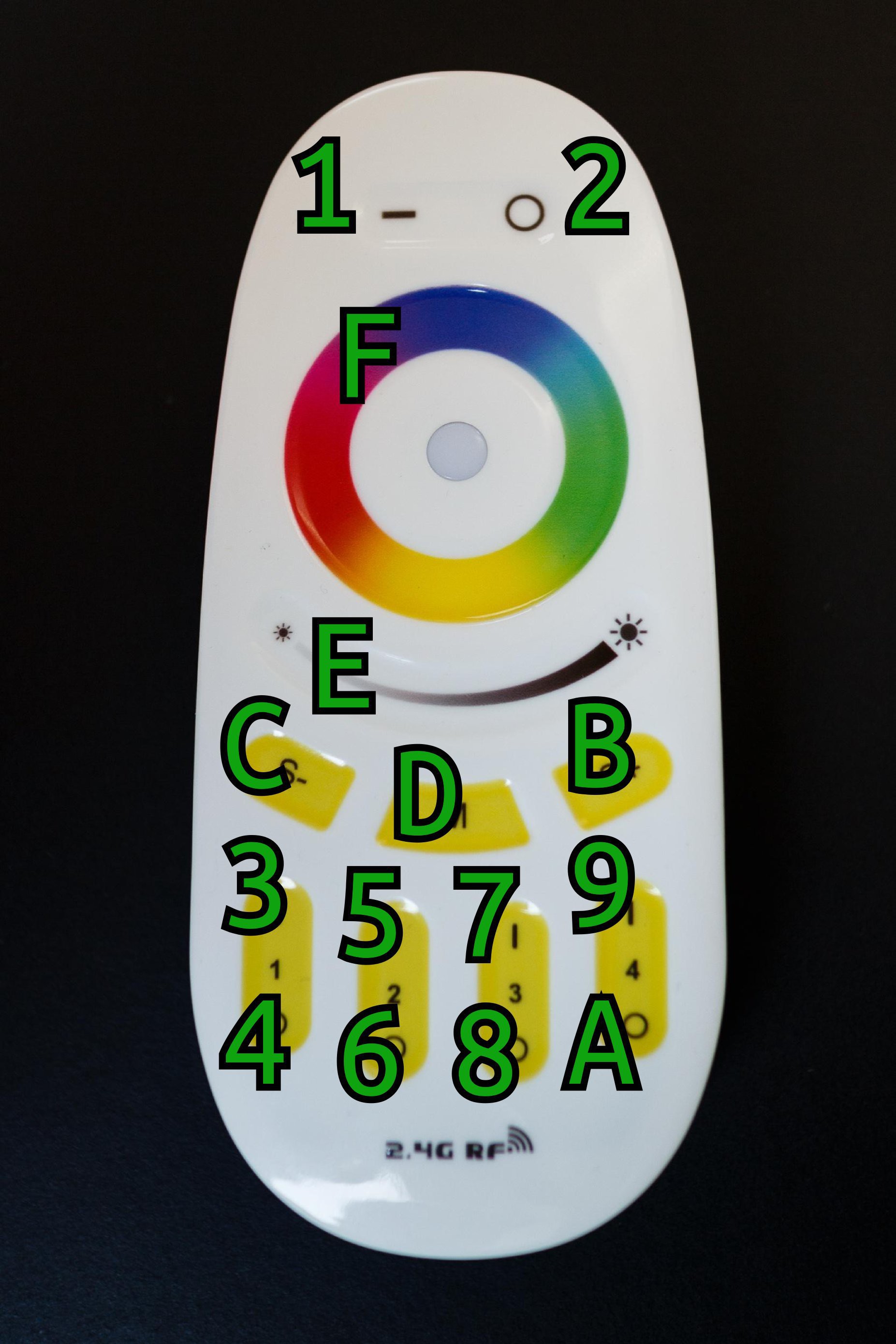
This is not a proper "command" set. This is just the current state of the remote control, transmitted in the most unimaginative way possible. By looking at the lower nibble of the CMD byte I can map it to the buttons on the remote as follows:
Now you know why they can't have more channels or additional features: There simply aren't any button codes left. Two more rules seem to apply:![]()
- 00 means that no button is touched, which only happens if you use one of the touch sliders and then let go: The remote streams every intermediate value immediately with no resends, but then adds the customary amount of resends –with different CMD but identical counter!– after you let go.
- The least significant bit of the upper nibble in the CMD byte indicates a long press on the corresponding button: 0x11 is "all: white", 0x12 is "all: night mode", 0x13 is "group 1: white", and so on. This applies even to the disco mode buttons (but doesn't seem to trigger any functionality in the bulb), but obviously not the sliders.
The value of the sliders are as follows:
- VAL1 is color. Goes from 0x00 all the way round to 0xFF. 0x00 is 9 o'clock on the slider (a purple), approx. 0x1B is half past 7 (pure red), 0x80 is 3 o'clock (a cyan), approx 0xBA is 12 o'clock (pure blue).
- VAL2 is brightness: Goes from 0x90 at the leftmost end, down(!) to 0x00 in the middle, to 0xA8 on the rightmost end, in increments of 0x08.
There's one additional peculiarity: The very first byte immediately after the length seems to also encode information. For my remote it is 0xB0 most of the time, except when repeatedly pressing disco mode: Then it increments up to 0xB8 and overflows back to 0xB0. This value is kept when pressing other buttons, but reset on touching the color wheel. The value seems to directly select a disco mode. I was wondering before how that worked: switching disco mode on independent bulbs, then doing an "all on", and pressing disco mode again would select the same disco mode on all bulbs. That wouldn't be possible if the only information the remote transmitted was "next disco mode", because then the bulbs would easily desynchronize with respect to what the current mode was. The modes are:
Mode Description 0 Smooth color fading 1 Fade white on and off 2 Fade red, green, blue, white on an off 3 Jump between red, green, blue, yellow, purple, cyan, white 4 Random colors and brightnesses 5 Fade red on and off, blink red 6 Fade green on and off, blink green 7 Fade blue on and off, blink blue 8 All of the above, in order I'm not entirely sure yet if the 0xB0 is part of the remote/gateway ID (meaning the ID would have 20 bits) or something else entirely (making for an ID of 16 bits).
-
Packet Surgery
05/26/2015 at 13:43 • 0 commentsBased on what I knew so far I could a) describe the Mi-Light frame format (if not the contents) and b) try to map this to the nRF51 or nRF24 frame format. Way back in 2011 the neighbourly Travis Goodspeed described how to achieve promiscuous sniffing with the nRF24L01+. Even though I didn't use this technique here (having done both SDR and logic analyzer sniffing instead), you should read his post, since it contains some basic knowledge that also applies to the PL1167 format.
Below is the framing I deduced for both nRF51422 (in little endian mode) and nRF24L01+ (which seems to operate in big endian), illustrated using an example from my received data:
![]()
The graphic shows the bits I sniffed from the air (preamble bits that my decoder didn't output but which must have been there are shown in grey at the beginning; conversely: bits that weren't sent but just represent the idle radio are shown in grey at the end), and their value in units of 4 bits (little endian, hex). Below that is the PL1167 framing as it would have been at the sender, deduced from the PL1167 data sheet/user manual and logic analyzer traces. Note that there is a very inconvenient 4-bit "trailer" after the sync field.
I then, using the nRF51 Series Reference Manual section 17.1.2, mapped this to nRF51 RADIO peripheral frames, when using the radio in little endian mode, data whitening disabled, CRC disabled, lengths of S0, LENGTH and S1 set to zero. Both this and the nRF24L01+ layout are tested, that is, when configuring the radio with the addresses described I get a payload as displayed.
It's slightly unfortunate: Because the PL1167 preamble is so long, bleeding into the nRF sync field, and also due to that strange 4-bit trailer, the nRF "payload" contains part of the PL1167 sync field, the trailer and length field, and is shifted by a nibble. I have to demangle that in my firmware after receiving it from the radio (and "re-mangle" before sending). I investigated using the nRF51 advanced fields: S0 (0 or 1 byte), LENGTH (0 through 15 bits), and S1 (0 through 15 bits), but didn't get immediate success. If I could subsume the extra data into these fields and align the PL1167 and nRF51 payloads, I could use the nRF51 CRC mechanism and generally clean up my usage of the radio. Maybe I'll re-try the advanced approach later, the simple one is working for now.
Finally I've been using an nRF24L01+ module on an Arduino with the RF24 library. Getting this to work took several attempts: the nRF24L01+ seems to receive data in big endian byte and bit order, so I had to use a different address, and need to mirror each byte of the payload before interpreting.
For a proper framing implementation there's still the question of the CRC. The PL1167 documentation doesn't describe it, only saying that it's 16 bits. Luckily, I have a little tool, that I built for similar problems years ago. It allows me to brute force CRC parameters, even allowing for uncertainties regarding which data is included in the CRC. Running on the payload, optionally prepended with the length, the result is: CRC polynomial 0x8408, initial value 0, final XOR 0, calculated over the length byte and the payload, output LSByte first.
Implementing a full receiver with CRC check and dupe detection gave me a good look at the packet contents for the first time.
-
In The Digital Domain
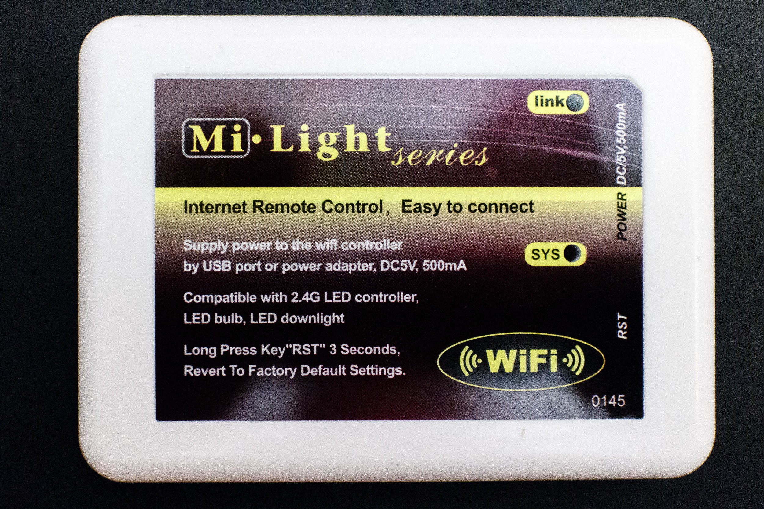
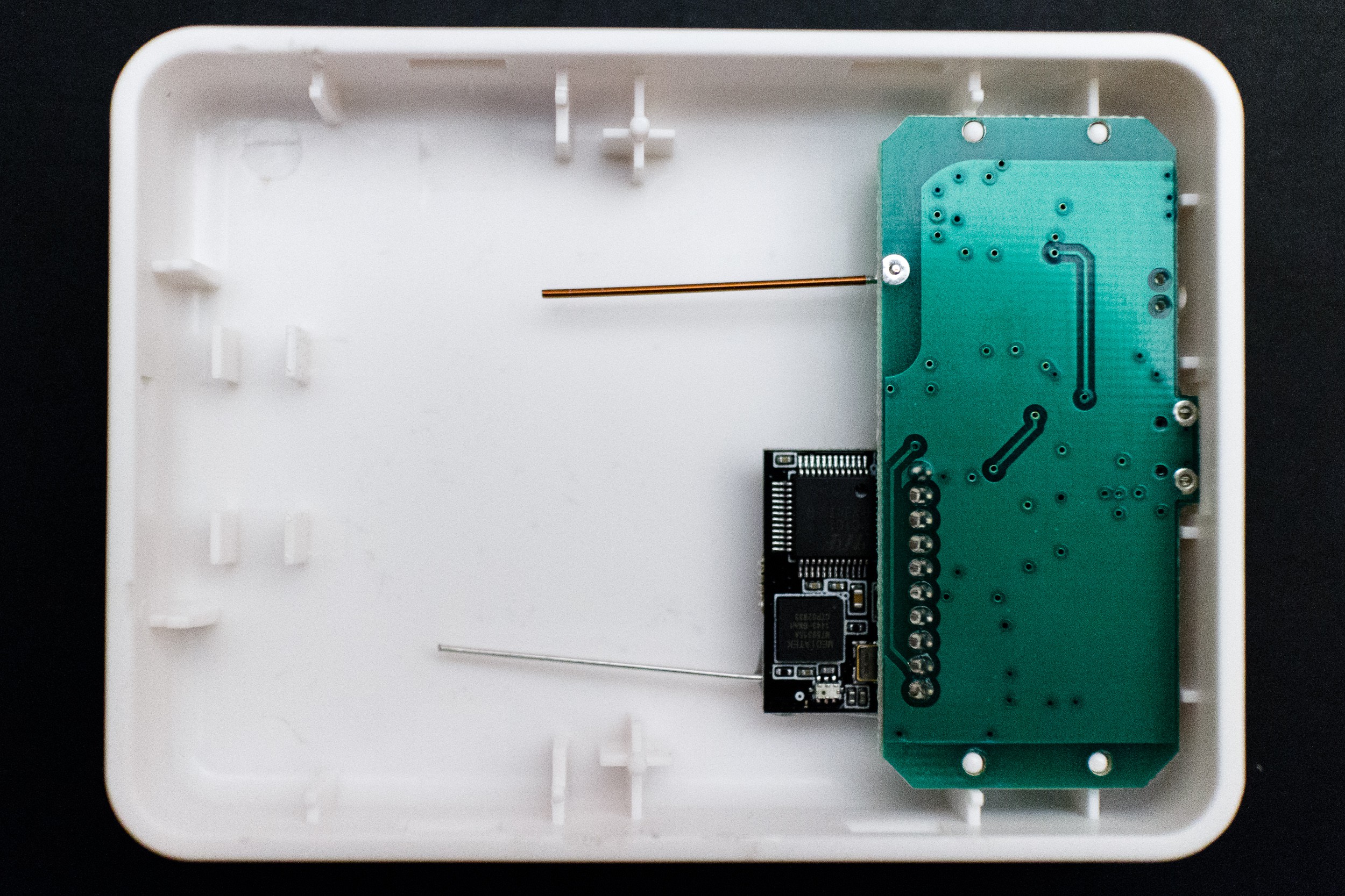
05/25/2015 at 15:23 • 1 commentI also wanted to sniff the communication between the micro controller and radio IC, but couldn't get the case of the remote control open. At the next opportunity I brought the Mi-Light Wi-Fi controller with me and got that open more or less easily:
![]()
![]()
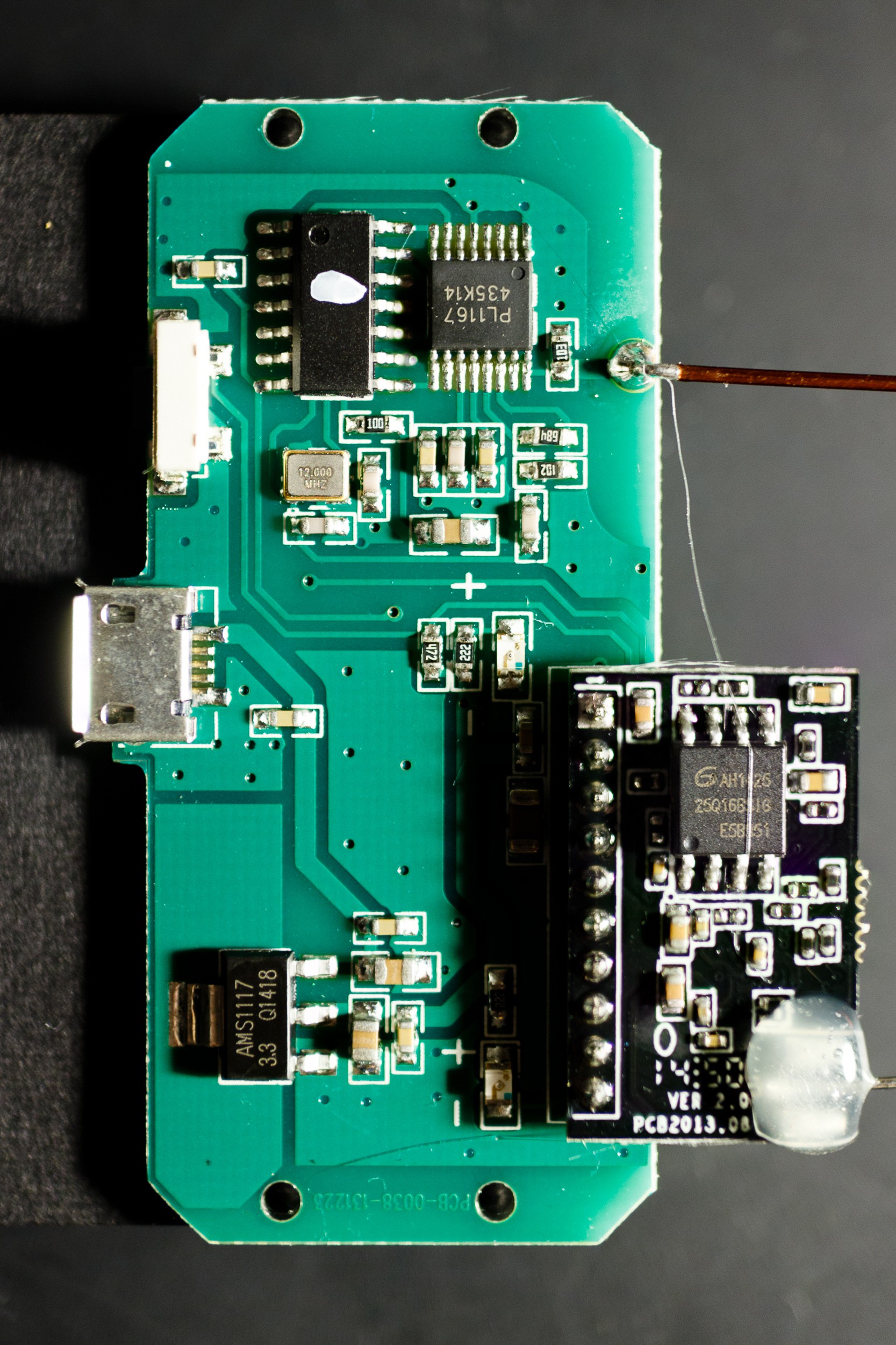
Inside wasn't much: a main board and, as I'd read before in the openhab group, a Wi-Fi daughter board connected to that, both with simple wire antennas.
![]()
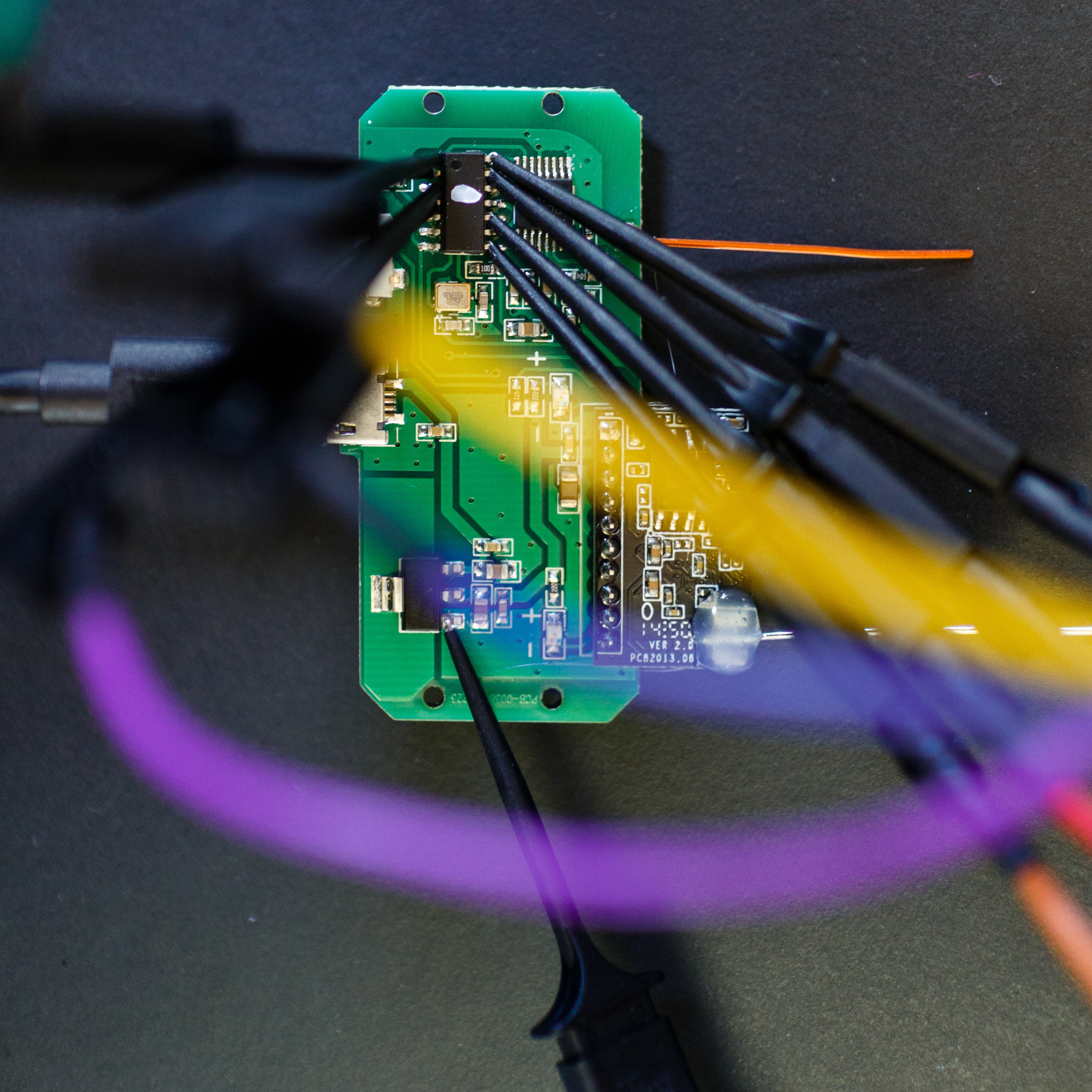
I knew that the connection between the boards wasn't interesting, since it only contains an UART with the command set I already know. I also know that that command set isn't related (in any obvious way) to the on-air protocol. That leaves me with a conclusion: The unmarked chip in the top left must be a microcontroller that implements the actual protocol and transmits commands to the PL1167 chip to the right of it. The PL1167 chip's leads seemed a little small to try to connect a logic analyzer, so instead I connected it to the microcontroller. I didn't know the pinout (except that center right is ground), so I just connected probes at random, hoping to catch something interesting (the probe at the bottom of the image is connected to ground).
![]()
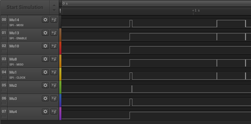
Counting counter clockwise from the marking on the microcontroller I got probes onto 1, 2, 3, 4, 8, 10, 13, and 14. I was using a Saleae Logic with their beta software for Linux (for some reason the 'stable' version would crash rather reliably). I also had the RF receiving set up, though it turned out that I didn't really need it:
![]()
And yep, sure enough, I got all four wires required for SPI among my sniffed traces, and can see some action when the device boots:
![]()
I had to play with the SPI settings to get this right (CPOL=0, CPHA=1), but it matches up with what the data sheet told me. Here you can see it writing the "Register Optimum Values" from the user manuals right after boot:
![]()
I exported the data from the Logic software as a CSV file and wrote a small python tool to decode and interpret the data, this is what happens on boot:
  1.17814875: Write reg  0 -> 6F E0
  1.17824850: Write reg  1 -> 56 81
  1.17834825: Write reg  2 -> 66 17
  1.17844775: Write reg  4 -> 9C C9
  1.17854750: Write reg  5 -> 66 37
  1.17864725: Write reg  7 -> 00 4C channel 76 (2478)MHz
  1.17874700: Write reg  8 -> 6C 90
  1.17884675: Write reg  9 -> 48 00
  1.17894650: Write reg  A -> 7F FD
  1.17904625: Write reg  B -> 00 08
  1.17914575: Write reg  C -> 00 00
  1.17924550: Write reg  D -> 48 BD
  1.17934525: Write reg 16 -> 00 FF
  1.17944500: Write reg 17 -> 80 05
  1.17954475: Write reg 18 -> 00 67
  1.17964450: Write reg 19 -> 16 59
  1.17974425: Write reg 1A -> 19 E0
  1.17984375: Write reg 1B -> 13 00
  1.17994350: Write reg 1C -> 18 00
  1.18004325: Write reg 20 -> 48 00 preamble length: 3 bytes, syncword length: 32 bits, trailer length: 4 bits, data type: NRZ, FEC: None
  1.18014300: Write reg 21 -> 3F C7
  1.18024275: Write reg 22 -> 20 00
  1.18034250: Write reg 23 -> 03 00
  1.18044225: Write reg 28 -> 44 02
  1.18054175: Write reg 29 -> B0 00 CRC on, first byte is length, FW_TERM_TX, initial CRC data: 00
  1.18064150: Write reg 2A -> FD B0
  1.18074125: Write reg 2B -> 00 0F
  1.39462075:  Read reg  0 -> 6F E0
  1.39473375:  Read reg  1 -> 56 81
  1.39484675:  Read reg  2 -> 66 17
  1.39495975:  Read reg  4 -> 9C C9
  1.39507300:  Read reg  5 -> 66 37
  1.39518600:  Read reg  7 -> 00 4C channel 76 (2478)MHz
  1.39529900:  Read reg  8 -> 6C 90
  1.39541200:  Read reg  9 -> 48 00
  1.39552525:  Read reg  A -> 7F FD
  1.39563825:  Read reg  B -> 00 08
  1.39575125:  Read reg  C -> 00 00
  1.39586425:  Read reg  D -> 48 BD
  1.39597725:  Read reg 16 -> 00 FF
  1.39609050:  Read reg 17 -> 80 05
  1.39620350:  Read reg 18 -> 00 67
  1.39631650:  Read reg 19 -> 16 59
  1.39642950:  Read reg 1A -> 19 E0
  1.39654250:  Read reg 1B -> 13 00
  1.39665575:  Read reg 1C -> 18 00
  1.39676875:  Read reg 20 -> 48 00 preamble length: 3 bytes, syncword length: 32 bits, trailer length: 4 bits, data type: NRZ, FEC: None
  1.39688175:  Read reg 21 -> 3F C7
  1.39699475:  Read reg 22 -> 20 00
  1.39710800:  Read reg 23 -> 03 00
  1.39722100:  Read reg 28 -> 44 02
  1.39733400:  Read reg 29 -> B0 00 CRC on, first byte is length, FW_TERM_TX, initial CRC data: 00
  1.39744700:  Read reg 2A -> FD B0
  1.39756000:  Read reg 2B -> 00 0F
  1.39767075: Write reg  7 -> 00 00 channel 0 (2402)MHz
  1.39776325: Write reg  7 -> 00 00 channel 0 (2402)MHz
  1.39785550: Write reg 34 -> 80 80 clear FIFO TX, FIFO write pointer: 0, clear FIFO RX, FIFO read pointer: 0
  1.39794525: Write FIFO: 06 00 00 00 00 00 00
  1.39819100: Write reg  7 -> 01 00 start TX, channel 0 (2402)MHz
And this is what happens when I send the "ALL ON" command every second:
  0.65326000: Write reg  7 -> 00 00 channel 0 (2402)MHz
  0.65336250: Write reg 24 -> 14 7A syncword 0: 147A
  0.65346500: Write reg 27 -> 25 8B syncword 3: 258B
  0.65357250: Write reg  7 -> 00 00 channel 0 (2402)MHz
  0.65367625: Write reg 34 -> 80 80 clear FIFO TX, FIFO write pointer: 0, clear FIFO RX, FIFO read pointer: 0
  0.65377725: Write FIFO: 07 B8 FD 4D 00 00 01 06
  0.65408750: Write reg  7 -> 01 09 start TX, channel 9 (2411)MHz
  0.65455775: Write reg  7 -> 00 00 channel 0 (2402)MHz
  0.65465950: Write reg 34 -> 80 80 clear FIFO TX, FIFO write pointer: 0, clear FIFO RX, FIFO read pointer: 0
  0.65475850: Write FIFO: 07 B8 FD 4D 00 00 01 06
  0.65506275: Write reg  7 -> 01 28 start TX, channel 40 (2442)MHz
  0.65549875: Write reg  7 -> 00 00 channel 0 (2402)MHz
  0.65560050: Write reg 34 -> 80 80 clear FIFO TX, FIFO write pointer: 0, clear FIFO RX, FIFO read pointer: 0
  0.65569975: Write FIFO: 07 B8 FD 4D 00 00 01 06
  0.65600375: Write reg  7 -> 01 47 start TX, channel 71 (2473)MHz
  0.65645225: Write reg  7 -> 00 00 channel 0 (2402)MHz
  0.65655400: Write reg 34 -> 80 80 clear FIFO TX, FIFO write pointer: 0, clear FIFO RX, FIFO read pointer: 0
  0.65665300: Write FIFO: 07 B8 FD 4D 00 00 01 06
  0.65695725: Write reg  7 -> 01 09 start TX, channel 9 (2411)MHz
  0.65741375: Write reg  7 -> 00 00 channel 0 (2402)MHz
  0.65751550: Write reg 34 -> 80 80 clear FIFO TX, FIFO write pointer: 0, clear FIFO RX, FIFO read pointer: 0
  0.65761450: Write FIFO: 07 B8 FD 4D 00 00 01 06
  0.65791875: Write reg  7 -> 01 28 start TX, channel 40 (2442)MHz

[… etc …]

  1.66702425: Write reg  7 -> 00 00 channel 0 (2402)MHz
  1.66712650: Write reg 24 -> 14 7A syncword 0: 147A
  1.66722900: Write reg 27 -> 25 8B syncword 3: 258B
  1.66733675: Write reg  7 -> 00 00 channel 0 (2402)MHz
  1.66744050: Write reg 34 -> 80 80 clear FIFO TX, FIFO write pointer: 0, clear FIFO RX, FIFO read pointer: 0
  1.66754150: Write FIFO: 07 B8 FD 4D 00 00 01 07
  1.66785150: Write reg  7 -> 01 09 start TX, channel 9 (2411)MHz
  1.66832175: Write reg  7 -> 00 00 channel 0 (2402)MHz
  1.66842350: Write reg 34 -> 80 80 clear FIFO TX, FIFO write pointer: 0, clear FIFO RX, FIFO read pointer: 0
  1.66852250: Write FIFO: 07 B8 FD 4D 00 00 01 07
  1.66882675: Write reg  7 -> 01 28 start TX, channel 40 (2442)MHz
  1.66926300: Write reg  7 -> 00 00 channel 0 (2402)MHz
  1.66936475: Write reg 34 -> 80 80 clear FIFO TX, FIFO write pointer: 0, clear FIFO RX, FIFO read pointer: 0
  1.66946375: Write FIFO: 07 B8 FD 4D 00 00 01 07
  1.66976775: Write reg  7 -> 01 47 start TX, channel 71 (2473)MHz
  1.67021650: Write reg  7 -> 00 00 channel 0 (2402)MHz
  1.67031800: Write reg 34 -> 80 80 clear FIFO TX, FIFO write pointer: 0, clear FIFO RX, FIFO read pointer: 0
  1.67041725: Write FIFO: 07 B8 FD 4D 00 00 01 07
  1.67072125: Write reg  7 -> 01 09 start TX, channel 9 (2411)MHz
So, that tells me mostly what I knew already, but more precise on some points. One new information is that they don't just transmit on 2.411GHz, but also on 2.442 and 2.473, and has 40 repetitions per transmission. Well, I guess it's one way to make the communication seem reliable. This likely means that the bulbs constantly hop between receiving on these three frequencies.I also now know in detail how the on-air packet is constructed and can apply this knowledge towards an independent implementation.
-
In The Radio Domain
05/25/2015 at 12:19 • 0 commentsThe first step in reverse-engineering any radio protocol is to listen to it on the air. The advent of software-defined radio makes this much, much, easier than before. For this project I've used a nuand bladeRF board and the GNURadio software stack, specifically gnuradio-companion.
![]()
The first task I set out to achieve was finding the frequency the devices communicate on. From the data sheet I knew that there are 128 channels in 1MHz spacing starting at 2.402GHz. In GRC I connected the bladeRF source to a FFT display with peak hold mode and then pressed buttons on the Mi-Light remote, positioned directly next to the antenna, while switching through receiving frequencies. I found that something would happen on 2.411GHz every time I touched the remote.
Next I wanted to look at the recorded signal more closely in the swiss army knife of signal analyzing: baudline, but for reasons that are not entirely clear to me I couldn't get the raw recording to load in baudline (or it would always crash immediately). Well, OK then, on to some speculative signal processing in GRC: I assumed amplitude modulation, because that's what all my previous RFID projects used, and so I connected a Frequency Xlating band pass filter and a simple complex-to-mag block in between the signal source and a scope. If I made the band pass narrow enough, I would get something akin to a data signal in the scope, but it didn't look pretty.
I re-checked the PL1167 data sheet, which I should have done before, and there it was spelled out rather clearly: The chip uses GFSK, a type of frequency modulation. Yes, if you put a narrow band pass on one of the frequency bands used by FSK you will get something similar to the original signal. But that's not the proper way to decode FSK. Truth be told, I don't know the proper way to decode GFSK, but I've seen someone on the internets use a quadrature demod block for the purpose, and sure enough, it seemed to work.
![]()
Now that I had a demodulated signal, I simply saved that as a .wav file and could look at it in baudline at my leisure. I identified a 10101010… preamble used to prep the receiver and could deduce the bit timing (4 samples per bit, or, at my sample rate of 4MHz, 1 Mbit/s – I could have gotten that from the data sheet).
I wrote Python code that consumes the recorded samples, looks for a strong signal and the preamble and then decodes the signal into bits that are written to stdout:
![]()
So that looks quite good already: Aligning on the first 111 tells me that most of the received data is identical, except for some changing bits at the end. Visually I identified a counter at the end, followed by 16 bytes that seemed to change at random (most likely a CRC). Aligning it so that the counter wasn't split between bytes, decoding as little endian (I got that from the counter), gave me a list of bytes transmitted:
47 B1 58 52 07 B0 F2 EA 76 10 01 8A 22 C5 FF 03 00 00 00 00
47 B1 58 52 07 B0 F2 EA 76 10 01 8A 22 C5 FF 03 00 00 00
47 B1 58 52 07 B0 F2 EA 76 10 01 8A 22 C5 FF 03 00 00 00 00
47 B1 58 52 07 B0 F2 EA 03 10 0F 8B A9 7A FF 03 00 00 00
47 B1 58 52 07 B0 F2 EA 03 10 0F 8C 16 0E FF 03 00 00 00 00
47 B1 58 52 07 B0 F2 EA 03 10 0F 8D 9F 1F FF 07 00 00 00
47 B1 58 52 07 B0 F2 EA 03 10 0F 8E 04 2D FF 03 00 00 00
I already could tell: Most commands are sent as ~30 copies (with same counter value). Except for color/brightness changing, that seems to be streamed (with a new counter value per transmission) as long as the finger is on the wheel, and then when taking the finger off the wheel the end is repeated (with same counter value) again ~30 times. -
Preliminaries
05/24/2015 at 18:15 • 0 commentsHardware
I have bought a set from Amazon: 4 Mi-Light bulbs (E27, 6W), remote control, and Wi-Fi gateway. The components perform as advertised: using the remote control is reliable and immediate, lamp brightness is ok, colors are great. There's a big disappointment though: These aren't RGBW lamps! These are, to coin a phrase, HV⊕V lamps: You can have them either in color or in warm white mode, and in color mode you can only set hue and value (brightness), while in warm white mode you can only set the brightness. You cannot change the saturation and you cannot combine white and colored LEDs.
Software
As documented elsewhere, the Wi-Fi gateway creates its own password-less Wi-Fi network to which you can connect and has a web interface with username/password admin/admin through which you can join it to your home Wi-Fi network. (Actually, my access point lets me create multiple virtual SSIDs that can be mapped to VLANs and I did so here: The Mi-Light Wi-Fi gateway is connected to a special separated network and does not have internet connectivity.) I've never used the accompanying phone app.
Instead I'm using the Wi-Fi gateway with the WifiLight module for FHEM (a home automation framework I use). This works mostly reliably, but the delay/refresh rate is awful. I'm using the same module with an LD382 Wi-Fi LED strip controller which can easily sustain one command every 150ms. With the Mi-Light gateway it's more like one command per second.
Existing Documentation
LimitlessLED (one of the names under which Mi-Light bulbs are sold) publishes a lengthy and not well organized developer page with lots of information and something they call OpenSource API. What it is though is a listing of all the commands that you can send to the Wi-Fi gateway, and that's already a big help. Besides the FHEM module mentioned above, there already is a lot of code in all the programming languages of the world (including PHP und bash) to send commands to the gateway.
In the openhab (which is another home automation framework) Google Group there is a thread from someone who has opened their bridge, discovered that it consists essentially of two boards (a Wi-Fi to UART side, and an UART to proprietary 2.4GHz side) and replaced the Wi-Fi connection with a wired LAN connection for better reliability. This thread contains a lot of information: It lists the 2.4GHz chip for the proprietary RF system as a PL1167 and even has data sheets for the PL1167. The protocol on the UART connection is simply the same protocol as on the Wi-Fi: the Wi-Fi→UART converter is a dumb standard component that is not Mi-Light specific.
Some of this information was previously collected and linked to from https://wikidevi.com/wiki/MiLight, there's also a link to a Mi-Fi bulb teardown.
Reverse-Engineering the milight on-air protocol
Mi-Light/Limitless LED are a type of RGB(W) LED lamps with standard light bulb sockets and a proprietary 2.4GHz radio control protocol
 Henryk Plötz