DIY Augmented Reality Device
... with video pass-through ...
... with video pass-through ...
To make the experience fit your profile, pick a username and tell us what interests you.
We found and based on your interests.
Ok, it's been some time since last log, and I changed a lot of things. Until then, I worked a lot on the hardware, and just coded a basic pygame script to experiment my changes. So, this code was very unoptimized, with one single big loop. It was time to work on this part.
 |  |
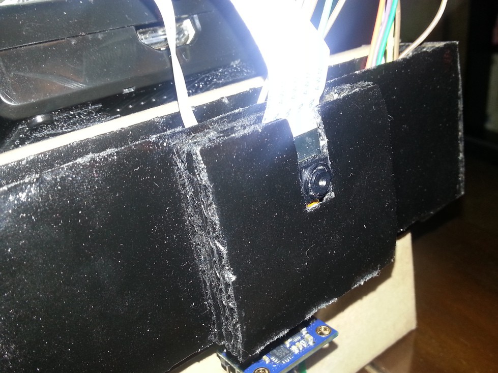
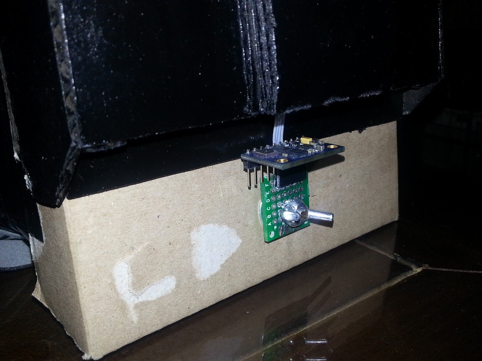
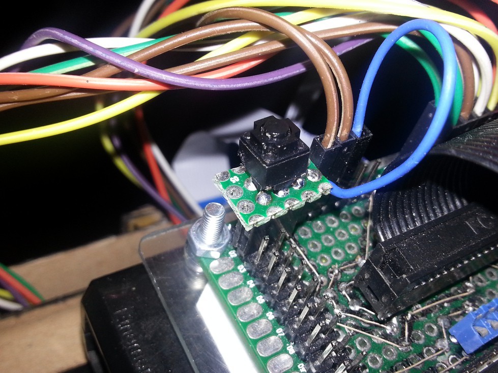
So, so far, the device is running well. The biggest problem is about the displays. Once I will have upgraded to a HDMI display, I won't be limited by framerate. I also plan to upgrade to a Raspberry Pi 2, to give some room for OpenCV video processing. I have so many ideas at this point...
But even at 10fps and with 240*320 resolution per eye, it's a great device and I don't feel any VR sickness with it.
I will release the full code on my GitHub once the cleanup is finished.
A last detail : I tried to use a BeagleBone at a point, because I have a very nice 7" 1024*600 display for it. But I quickly found the USB bandwith is also limited, and I could not capture at more than 10fps with a USB webcam. There's nothing I could do to it, so I abandonned the idea. I don't want to kill my only beagleboard doing a similar hack I did on the Pi. 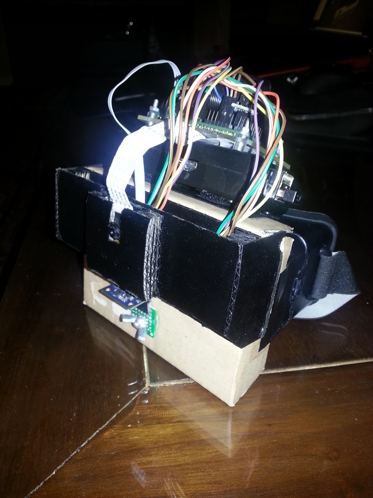
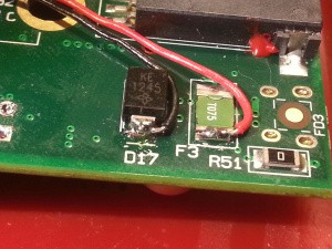
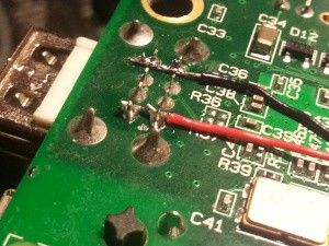
The first version of the HMD had a few little problems :
So I decided to make some modifications :
All these modifications allow me to put the raspberry on the top of the HMD. It's far less bulky, more robust and I can put it on a table...
With these modifications, I can say the issues I was facing are totally gone : image quality is far better, no more light is entering the device, and flickering has stopped.
Here are a few pictures, see more on this page.
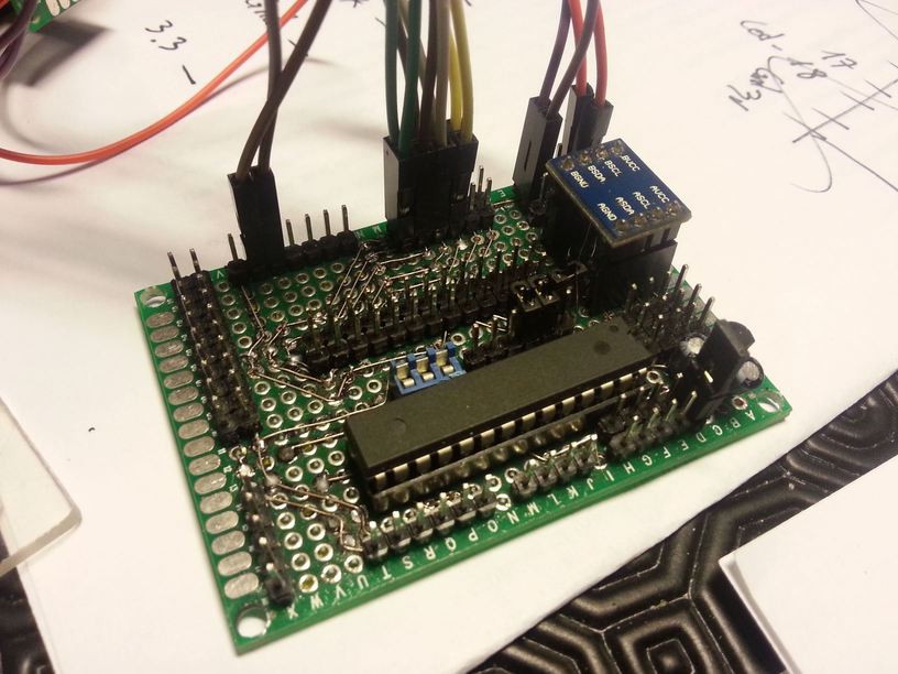
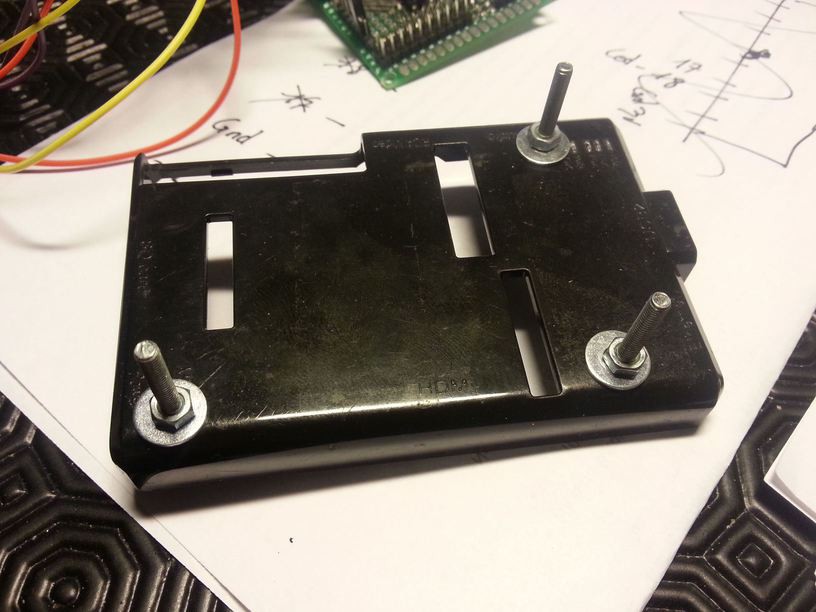
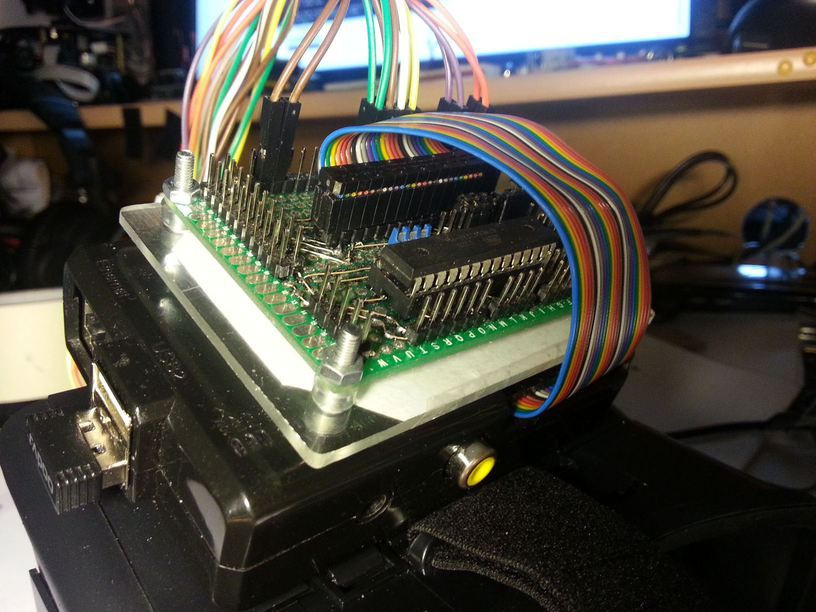
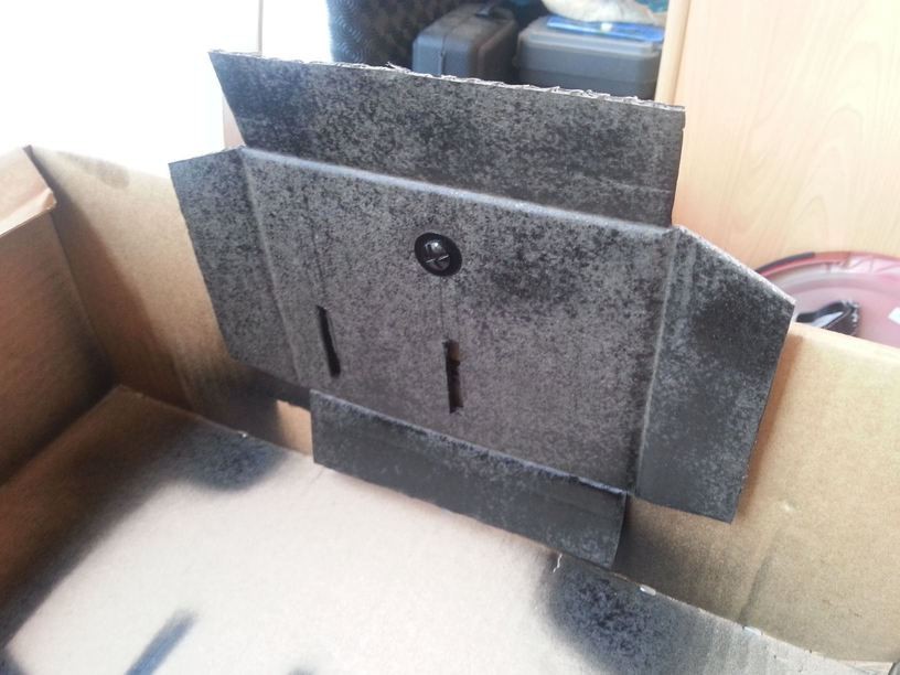
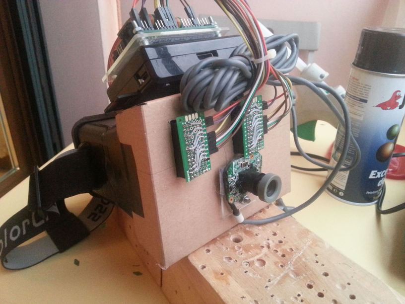
Better look, isn't it ?
In Day 1, I made both SPI displays to work in clone mode. They could achieve 50fps which is very good, and they seem to be synced (I will have to check this when the helmet is working)
Today, I'm starting to physically build the device.
Here is how both displays are connected :
Common to both displays :
For each display :
Because I want to reuse displays in other projects in the future, I don't want to alter them. So I will build some adapters, to go from both display's 26 pins connector to the Raspberry Pi's 26 pins connector.
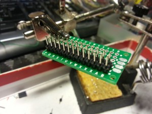 | 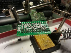 |
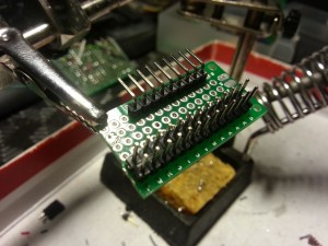 | 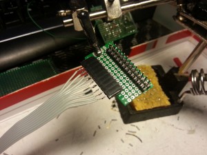 |
Unfortunately, after a quick test in the shell, I notice I can't use the displays horizontally : they are too far away from each other to fit the lenses. So, I will use them vertically.
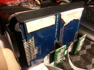
When used vertically, both display fit perfectly in the ColorCross shell.
I can now test the lenses alignment. Once perfect alignment is found, I will attache both displays to the shell with a little hot glue (sticks well and is easy to remove)
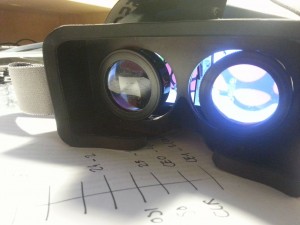 |  |
Displays are rotated in the pictures, but the overlay I linked to in Day 1 corrects this.
Without any surprise, view is pixellated, but it's not really important right now, and I have plans to drastically improve it in a future upgrade.
Good news is : displays are perfectly synced ! So this build is viable, after all !
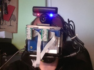 | 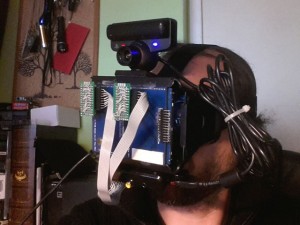 |
PS3 Eye camera and Raspberry Pi have been temporary attached on top and bottom of the shell with velcro.
Very sexy, isn't it ? :D
The first stage is to get both SPI displays to work in clone mode. I will call this first version "Mark I" :)
First, we have to physically connect them.
Then, we have to build a new dual_hy28b_nots overlay. Display and touchpanel both use a SPI chip select (CS) line and Raspberry Pi have only one SPI channel with two CS lines, so we have to remove touchscreens in order to activate both displays.
Finally, we will add some modifications to X11 to allow clone view with both SPI displays.

Full guide is available in french on this link
I think you could easily follow the quotes, if not, please send me a message !
Create an account to leave a comment. Already have an account? Log In.
plz can u tell the connection for pi 3(with pin no. Or pin name(as there are tp_sckand lcd_sck,etc) and what to do after that. (I mean just to follow ur steps or sth more) and also which raspbian image should i use so that ur code will run?will it run with noobs?thanx in advance
Hi Mike, thanks ! The Raspberry Pi B I'm currently using could drive both displays at 50fps but I slowed them down to 30fps because of the long cables. I was really surprised to notice both displays are perfectly synced.
The bottleneck right now seems to be usb bandwidth : I could not capture at more than 10fps, even without processing, even if one camera I tested could achieve 30fps on another board (but this board could not drive both displays at the same time).
Right now, with my current code, I could achieve capture@8fps and display@30fps, with 10dof IMU processing and showing some data and graphics on both displays. Very cool, even at 8fps.
I believe an upgrade to a Raspberry Pi 2 with its quad core and 1gb RAM could achieve 25-30 fps with face detection enabled.
Wow, cool build. Do you anticipate any speed problems with the Raspberry Pi? I wouldn't think it is fast enough to drive both displays and still do image processing but I don't know for sure.
After a lot of tweaking, I achieve full framerate with the raspberry camera module in python, and 27-30fps with usb cam, depending the light. However, because each display uses half the SPI bandwith, they can only output 10-12fps, but are in sync. Display upgrade is planned to get a lot higher resolution and fps..
Become a member to follow this project and never miss any updates
Hey I love your project and hope to make a futuristic motorcycle helmet with IR and FLir style video overlay while riding, as well as fun overlays like weather and stuff. Let me know if your still on here