Beamsjr
-
Finished wiring it up
04/24/2014 at 10:33 • 0 commentsThis morning I finished wiring the flux capacitor up to the breadboard while I wait for the board to come in. I now have a fully functioning flux capacitor. I wont be getting the board in before the end of the contest so It is not 100% complete, but all functionality is complete and it works, so hopefully we will get a shirt!
-
Setup node server
04/24/2014 at 02:17 • 1 commenttonight I wrote a small node server to scrape the skulls from this project and update the flux capacitor delay with the amount of skulls I have. It will hit my project page every 15 minuets and if the value has changed will send a request to the flux capacitor to update.
var request = require('request');var cheerio = require('cheerio');var url = 'http://hackaday.io/project/594-Wireless-Flux-Capacitor';
var fc = 'http://192.168.1.98/delay/';
var prevLikes = 0;
console.log("Starting");req();
function req() {setTimeout(function(){request(url, function(err, resp, body) {if (err)
throw err;
$ = cheerio.load(body);
var likes = $('#like_count').text();if(likes != prevLikes){var delay = 300 - parseInt(likes, 10);
console.log(delay);
prevLikes = likes;
setDelay(delay);
};
});
req();
}, 900000);
}
function setDelay(delay){request(fc + delay, function(err, resp, body) {console.log(body);
});
}
-
Sketch is working.
04/20/2014 at 13:37 • 0 commentsI got the cc3000 wireless module in and started coding. I have got everything working and just need to get my main board in. I have commited the code to
https://github.com/beamsjr/Arduino_CC3000_FluxCapacitor The code works by receiving a PUT request,
example: http://192.168.1.69/delay/50
While the flux capacitor only has one method, I built the code to split up the url into a method and value, which would allow me to expand the feature set pretty simply to support more methods if i need to.
-
Change of plans
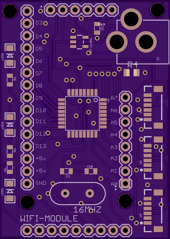
04/17/2014 at 12:59 • 0 commentsI have decided to make a change from wired ethernet to wireless after learning about the new CC3000 module from Ti. I should have the module in in the next few days, so I will get it on a breadboard and start testing out some code to get it working. I have redesigned the control module to add the breakout headers for the wifi board and added pinouts for the digital and analog pins so I can easily breadboard the module and reuse it if i choose. I also added rx , tx and power leds to the board. Below you will find the layout I ended up with.
![]()
-
Received LED boards
04/07/2014 at 15:11 • 0 commentsOver the weekend I received the LED boards. I had ordered 2 sets. One with breadboard mountable header for testing, and another with a GPS style micro connector. I got some LED's soldered on the breadboard compatible one and tested, I was relieved to see it worked first try. Looks so much better than the through hole led's I was testing with. I went ahead and started on the boards with the micro connector, got them all soldered and hooked them up. Uh oh, something's not right! I'm getting all kinds of weird sequences coming out. Two days later and a lot of head smashing I finally realized I had changed the connector layout on the mini connector, change a few pins around and I'm all set!
-
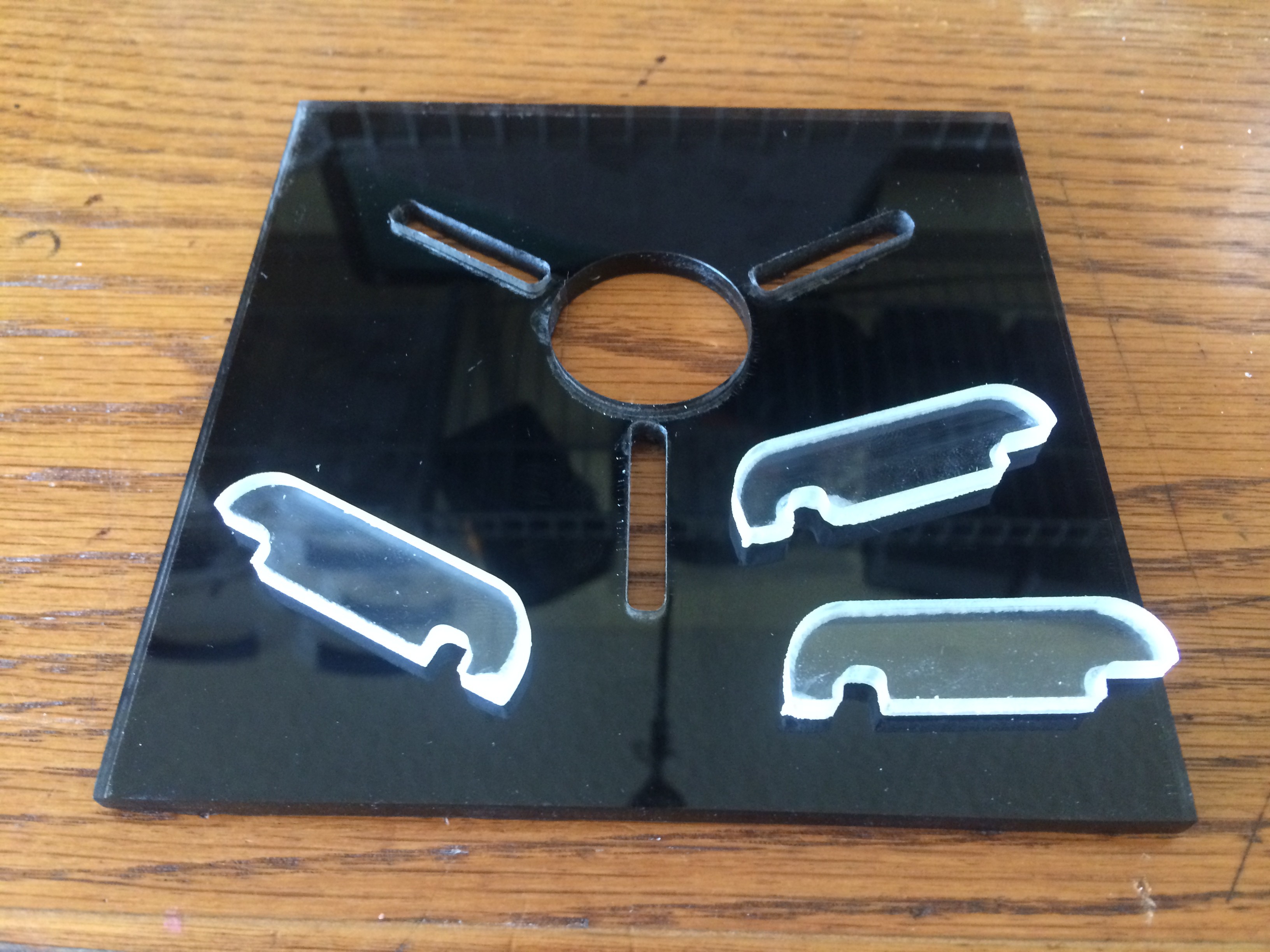
Some more progress...
03/31/2014 at 23:18 • 0 commentsI re-cut the base with acrylic and painted the back black, I think it looks much better than what I had before. I still haven't got down the right speed on the cnc for acrylic, I get a little bit melted plastic around the bit which scuffs the edges. I assume I have the router speed to high. It looks worse in the photo than it does in real life. Most of it is covered up in the case anyway. Here is a pic of the base and arms.
![]() Then I threw together the top part of the case and cut it out of MDF, a little sanding and its ready for primer.
Then I threw together the top part of the case and cut it out of MDF, a little sanding and its ready for primer. ![]() I think im going to paint the case grey like the "real" flux capacitor. What do you think?
I think im going to paint the case grey like the "real" flux capacitor. What do you think? -
Started layout
03/30/2014 at 02:56 • 0 commentsTonight I staretd laying out flux capacitor. I went ahead and cut out the base and acrylic parts to see what it would look like, I will probably try and find a different material for the base, I dont love the look of it at the moment, but it is progress.
![]()
-
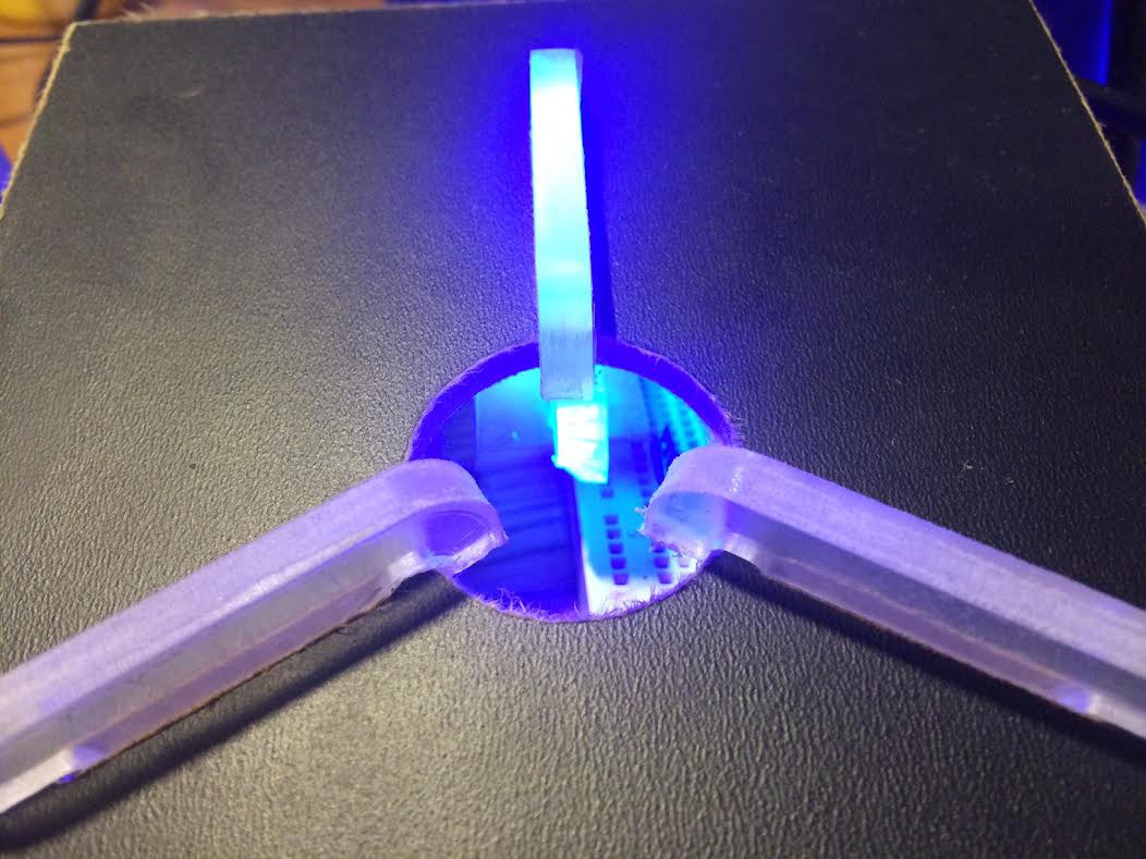
Started coding
03/29/2014 at 12:42 • 2 commentsLast night I started coding and testing the shift register. This was the first time I have ever used a shift register and was surprised how easy it was. There is a nice tutorial at http://arduino.cc/en/tutorial/ShiftOut . I used the toner transfer method to make a quick test board with 8 LEDs and a shift register while I wait for my boards to come in. I took a piece of lexan and glued to the top if the LEDs to act as a defuser. I shot a quick video of the result.
-
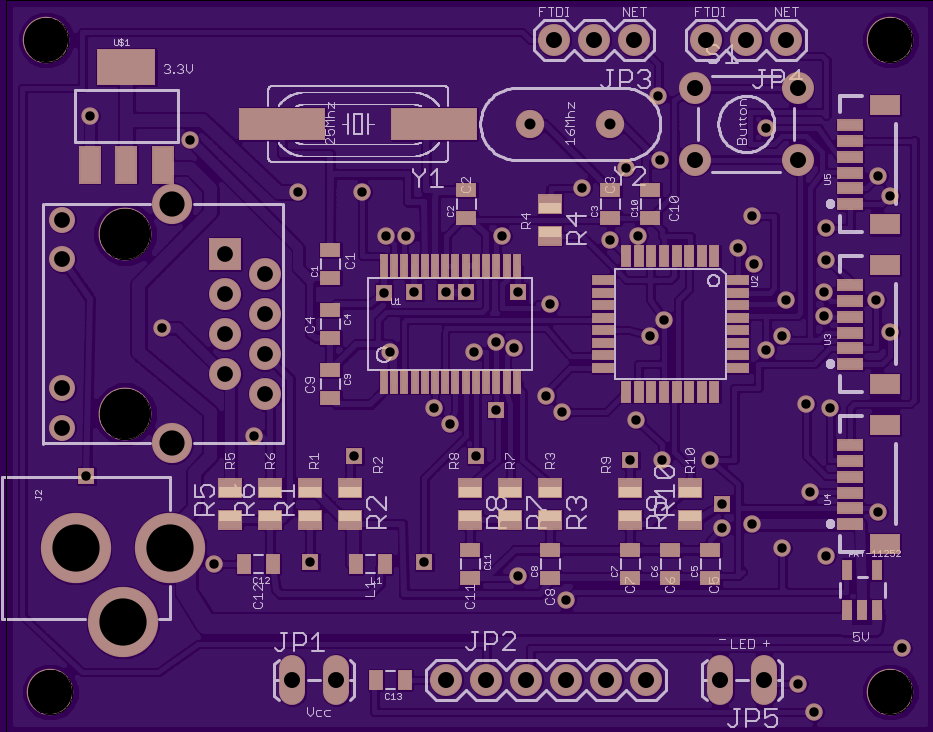
Finished design of the controller
03/28/2014 at 03:06 • 0 commentsI spent a few more hours tonight hacking together the control unit, sent the order off to OSHpark, crossing fingers hoping I didn't forget anything. This will definitely be the most complex board i have had made to date. The only thing I dont like is that even though I hid the top names OSHpark automatically grabs them and adds them back to the silkscreen. I couldnt find in eagle how to move the names that are in the footprint. i thought I could just hide them and add my own on another layer, so now i have duplicate names on the components. I guess next I will start working on the enclosure while I wait for the boards to come in.
![]()
-
Scraped control module design
03/27/2014 at 11:27 • 0 commentsOk, so I decided the wiznet w5100 pins were just too close together for this build, so I scraped the design and started over with the enc28j60 controller. I put most of it together last night. I should be able to finish it up tonight.
 Then I threw together the top part of the case and cut it out of MDF, a little sanding and its ready for primer.
  I think im going to paint the case grey like the "real" flux capacitor. What do you think?