Close
0%
0%

WeatherPi - Solar Powered Raspberry Pi Station

Similar projects worth following
Build a Raspberry Pi Based Weather Station

Build your own Raspberry Pi Weather Station, WeatherPi!
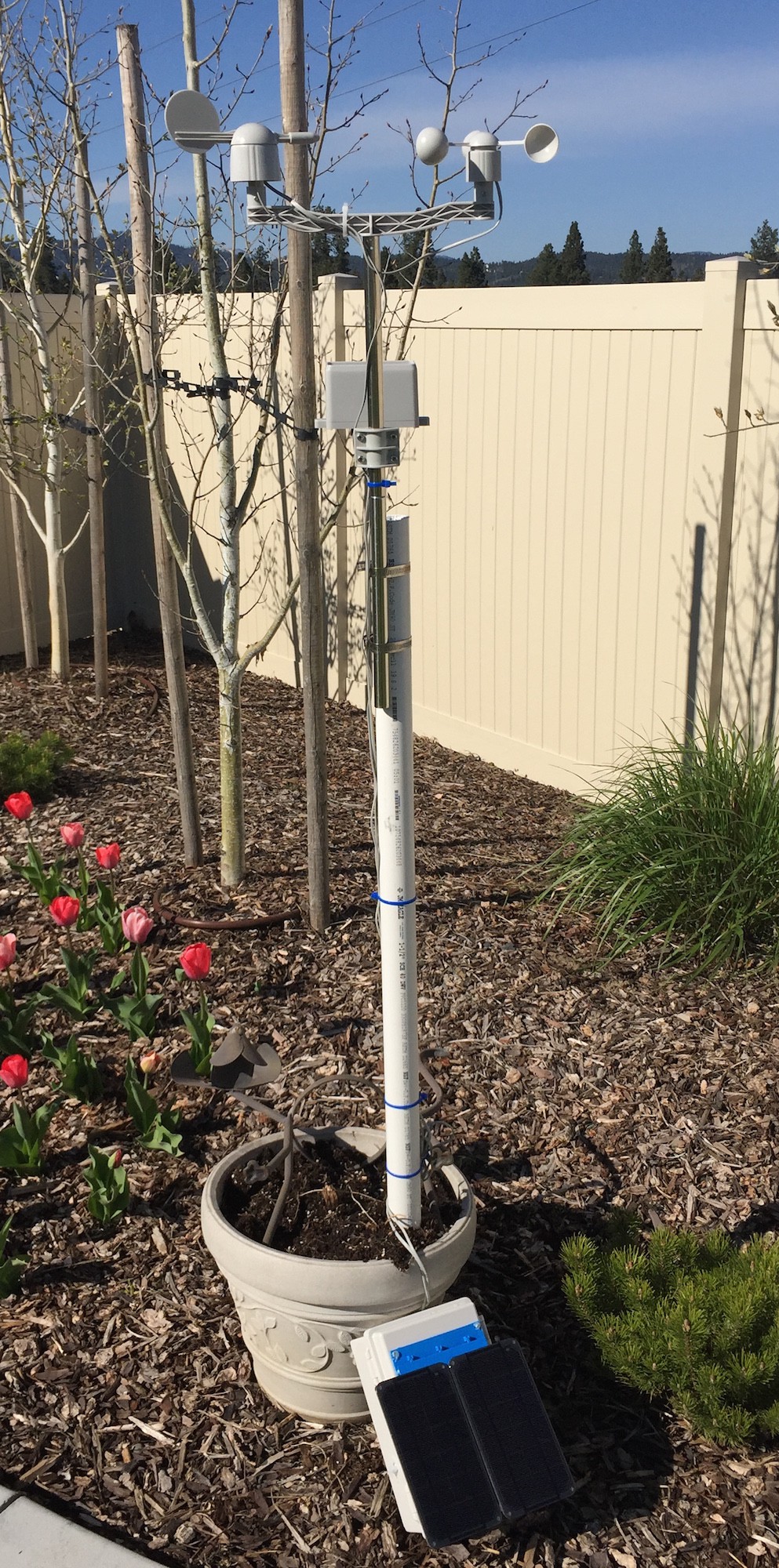

By doing this project you will learn:

  1. How to build a solar powered system
  2. How to design and size the panels and batteries
  3. How to gather data to analyze your system performance
  4. How to wire up a Raspberry Pi to a solar power system
  5. How to safely turn a Raspberry Pi on and off
  6. Building 3D Printed Parts for WeatherPi

And most importantly, have fun doing it!


What is WeatherPi?

WeatherPi is a solar powered Raspberry Pi WiFi connected weather station designed for Makers by SwitchDoc Labs. This is a great system to build and tinker with. All of it is modifiable and all source code is included. The most important functions are:

  • Senses 20 different environmental values
  • Completely Solar Powered
  • Has a full database containing history of the environment (MySQL)
  • Monitors and reports lots of data on the solar powered system - great for education!
  • Self contained and monitored for brownouts and power issues
  • Can be modified remotely
  • Download your data to crunch it on your PC
  • Can be modified to do SMS (Text) messaging, Twitters, webpages and more
  • Has an iPad Based Control Panel
  • Easy to connect to Twitter, WeatherUnderground, etc

This project will show you how to build a WiFi Solar Powered Raspberry Pi Weather Station. This project grew out of a number of other projects, including the massive Project Curacao, a solar powered environmental monitoring system deployed on the Caribbean tropical island of Curacao. Project Curacao was written up in an extensive set of articles in MagPi magazine (starting in Issue 18 and continuing through Issue 22).

The WeatherPi Solar Powered Weather Station is an excellent education project. There are many aspects of this project that can be looked at and analyzed for educational purposes:

  • How do solar power systems behave? Limitations and advantages
  • Temperature, Wind and Humidity data analysis.
  • Shutting down and starting up small computers on solar power
  • Add your own sensors for UV, dust and pollen count and light color

Follow along on updates to the WeatherPi story on www.switchdoc.com.
  • 1 Ă— Full Parts List in Build Instructions

  • 1
    Step 1

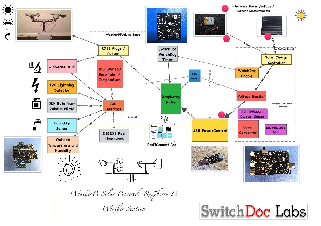
    The WeatherPi Block Diagram looks a lot more complicated than it actually is.

    The first thing to notice that the dashed lines are individual boards (WeatherPiArduino and SunAirPlus) which contain a lot of the block diagram and the second thing is that all of the sensors to the left of the diagram plug into the WeatherPiArduino board which simplifies the wiring. Don't be intimidated!

    The Subsystems

    The Power Subsystem of WeatherPi uses a SunAirPlus Solar Power Controller which handles the solar panels, charging of the battery and then supplies the 5V to the Raspberry Pi and the rest of the system. It also contains sensors that will tell you the current and voltage produced by the Solar Panels and consumed by the batteries and the Raspberry Pi. Gather that Data! More Cowbell! It also contains the hardware watchdog timer and the USB PowerControl that actually shuts off the power to the Raspberry Pi during a brownout event (after the Pi shuts gracefully down under software control).

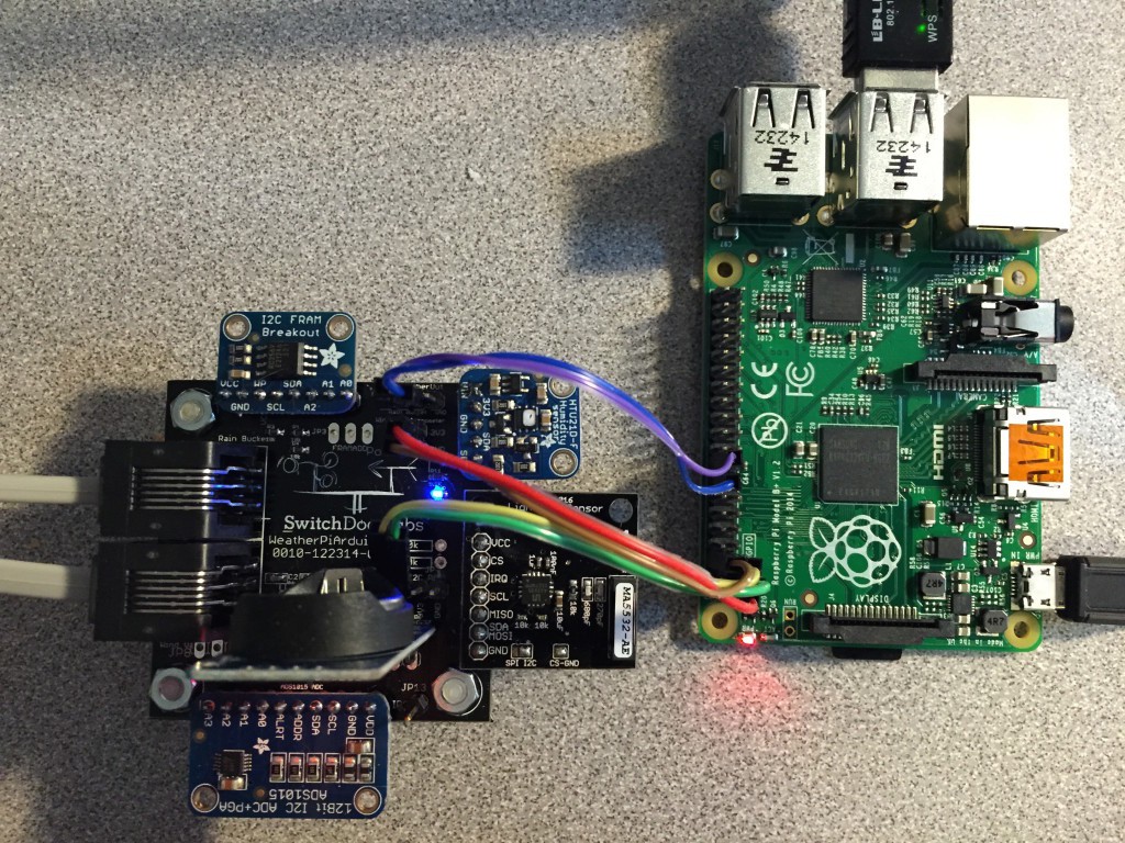
    The Sensor Subsystem of WeatherPi uses a WeatherPiArduino as the base unit and then plugs in a bunch of optional sensors such as wind speed / direction / rain, lightning detection (how cool is that!), inside and outside temperature and humidity.

    The Software Subsystem of WeatherPi runs in Python on the Raspberry Pi. It collects the data, stores in in a MySQL database, builds graphs and does housekeeping and power monitoring.

  • 2
    Step 2

    The WeatherPi Sensor Suite senses the following environmental values:

    • Wind Speed
    • Wind Direction
    • Rain
    • Outside Temperature
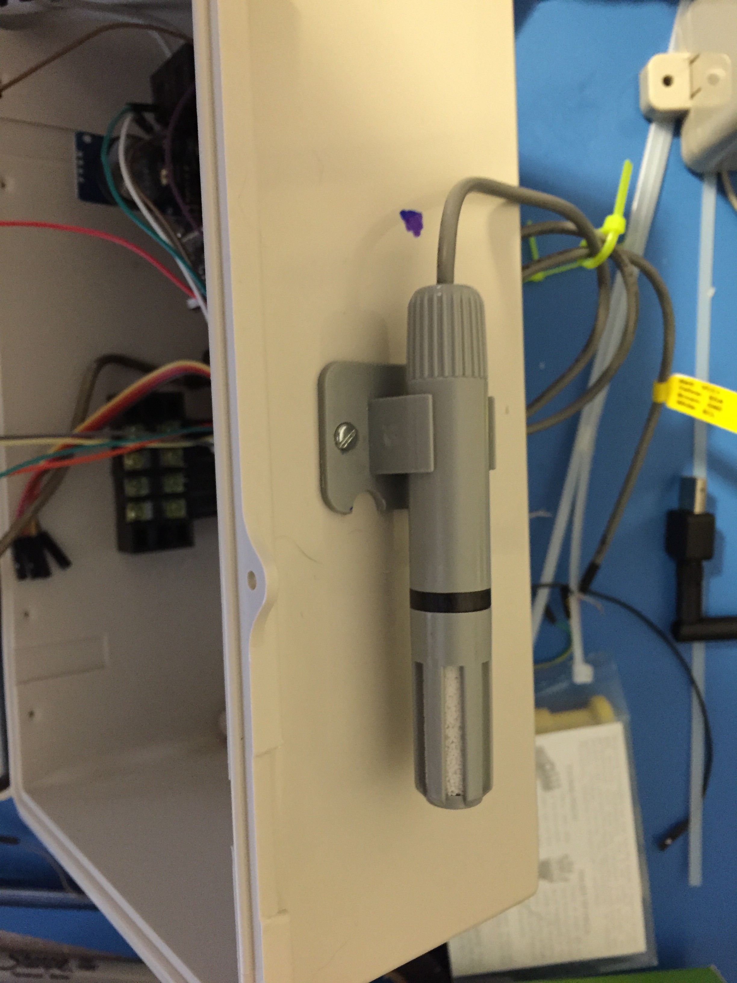
    • Outside Humidity
    • Lightning Detection
    • Barometric Pressure (and Altitude)
    • Inside Box Temperature
    • Inside Box Humidity

    You can add more to the I2C bus and Analog to Digital Converter such as UV, dust counts, light color (sensing some types of pollution) and more! It's a great platform for expansion.

    The sensor suite is built on the WeatherPiArduino board but there are several similar boards out there on the market.

  • 3
    Step 3

    What's On the I2C Bus?

    WeatherPi makes extensive use of the I2C bus on the Raspberry Pi.

    At SwitchDoc Labs, we love data. And we love I2C devices. We like to gather the data using lots of I2C devices on our computers and projects. Project Curacao has a total of 12, WeatherPi has 11 devices and SunRover (a solar powered rover under development at SwitchDoc - you will see it as an Project in fall 2015) will have over 20 and will require one I2C bus just for controlling the motors. We are always running into conflicts with addressing on the I2C device. Since there are no standards, sometimes multiple devices will have the same address, such as 0x70 and you are just out of luck in running both of them on the same I2C bus without a lot of jimmy rigging.

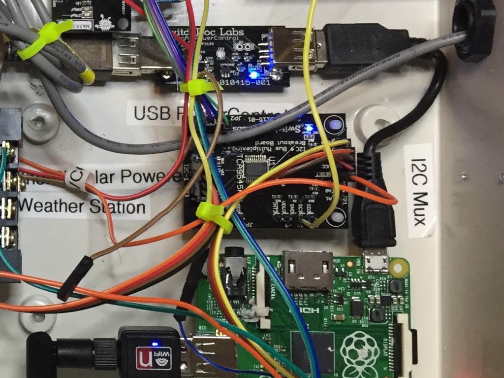
    To get around this addressing problem (and our conflict with an INA3221 and the Inside Humidity Sensor) we added an I2C Bus Multiplexer to the design which allows us to have many more I2C devices on the bus, irregardless of addressing conflicts. Here is our current list of I2C devices in WeatherPi:

    Device:I2C Address

    BMP180 Barometric Pressure: 0x77

    Real Time Clock DS3231: 0x68

    ATC EEPROM: 0x56

    ADS1015 Analog to Digital Converter: 0x49

    FRAM non-volatile storage: 0x50

    ADS1015 on SunAirPlus: 0x48

    INA3221 3 Channel Voltage/Current Monitor on SunAirPlus: 0x40

    HTU21D-F Humidity Sensor: 0x40

    Embedded Adventures Lightning Detector: 0x03

    AM2315 Outdoor Temp/Humidity: 0x5C

    I2C 4 Channel I2C Bus Mux: 0x73

    Here is what the I2C bus looks like on the Raspberry Pi. This is the output from the example code with the I2C 4 Channel Mux (hence there are 4 independent busses shown for the I2C bus).

    Note that WeatherPi only uses Bus 0 and Bus 1.

    Test SDL_Pi_TCA9545 Version 1.0 - SwitchDoc Labs
    
    Sample uses 0x73
    Program Started at:2015-05-10 20:00:56
    
    -----------BUS 0-------------------
    tca9545 control register B3-B0 = 0x1
    ignore Interrupts if INT3' - INT0' not connected
    tca9545 control register Interrupts = 0xc
         0  1  2  3  4  5  6  7  8  9  a  b  c  d  e  f
    00:          03 -- -- -- -- -- -- -- -- -- -- -- -- 
    10: -- -- -- -- -- -- -- -- -- -- -- -- -- -- -- -- 
    20: -- -- -- -- -- -- -- -- -- -- -- -- -- -- -- -- 
    30: -- -- -- -- -- -- -- -- -- -- -- -- -- -- -- -- 
    40: 40 -- -- -- -- -- -- -- -- 49 -- -- -- -- -- -- 
    50: 50 -- -- -- -- -- 56 -- -- -- -- -- -- -- -- -- 
    60: -- -- -- -- -- -- -- -- 68 -- -- -- -- -- -- -- 
    70: -- -- -- 73 -- -- -- 77                         
    
    -----------------------------------
    
    -----------BUS 1-------------------
    tca9545 control register B3-B0 = 0x2
    ignore Interrupts if INT3' - INT0' not connected
    tca9545 control register Interrupts = 0xe
         0  1  2  3  4  5  6  7  8  9  a  b  c  d  e  f
    00:          -- -- -- -- -- -- -- -- -- -- -- -- -- 
    10: -- -- -- -- -- -- -- -- -- -- -- -- -- -- -- -- 
    20: -- -- -- -- -- -- -- -- -- -- -- -- -- -- -- -- 
    30: -- -- -- -- -- -- -- -- -- -- -- -- -- -- -- -- 
    40: 40 -- -- -- -- -- -- -- 48 -- -- -- -- -- -- -- 
    50: -- -- -- -- -- -- -- -- -- -- -- -- -- -- -- -- 
    60: -- -- -- -- -- -- -- -- -- -- -- -- -- -- -- -- 
    70: -- -- -- 73 -- -- -- --                         
    
    -----------------------------------
    
    -----------BUS 2-------------------
    tca9545 control register B3-B0 = 0x4
    ignore Interrupts if INT3' - INT0' not connected
    tca9545 control register Interrupts = 0xc
         0  1  2  3  4  5  6  7  8  9  a  b  c  d  e  f
    00:          -- -- -- -- -- -- -- -- -- -- -- -- -- 
    10: -- -- -- -- -- -- -- -- -- -- -- -- -- -- -- -- 
    20: -- -- -- -- -- -- -- -- -- -- -- -- -- -- -- -- 
    30: -- -- -- -- -- -- -- -- -- -- -- -- -- -- -- -- 
    40: -- -- -- -- -- -- -- -- -- -- -- -- -- -- -- -- 
    50: -- -- -- -- -- -- -- -- -- -- -- -- -- -- -- -- 
    60: -- -- -- -- -- -- -- -- -- -- -- -- -- -- -- -- 
    70: -- -- -- 73 -- -- -- --                         
    
    -----------------------------------
    
    -----------BUS 3-------------------
    tca9545 control register B3-B0 = 0x8
    ignore Interrupts if INT3' - INT0' not connected
    tca9545 control register Interrupts = 0xc
         0  1  2  3  4  5  6  7  8  9  a  b  c  d  e  f
    00:          -- -- -- -- -- -- -- -- -- -- -- -- -- 
    10: -- -- -- -- -- -- -- -- -- -- -- -- -- -- -- -- 
    20: -- -- -- -- -- -- -- -- -- -- -- -- -- -- -- -- 
    30: -- -- -- -- -- -- -- -- -- -- -- -- -- -- -- -- 
    40: -- -- -- -- -- -- -- -- -- -- -- -- -- -- -- -- 
    50: -- -- -- -- -- -- -- -- -- -- -- -- -- -- -- -- 
    60: -- -- -- -- -- -- -- -- -- -- -- -- -- -- -- -- 
    70: -- -- -- 73 -- -- -- --                         
    
    -----------------------------------

View all 14 instructions

Enjoy this project?

Share

Discussions

jippo12 wrote 09/28/2020 at 10:25 point

Nice work! You should add camera there too ;)

  Are you sure? yes | no

pittemanjason wrote 09/27/2016 at 14:29 point

This is such a nice project! Nice work you've done there. I'm collecting information to build my own Weather Station with a Raspberry Pi. By now, this is by far the best project I've seen ;)

  Are you sure? yes | no

Similar Projects

Does this project spark your interest?

Become a member to follow this project and never miss any updates