The following changes were made
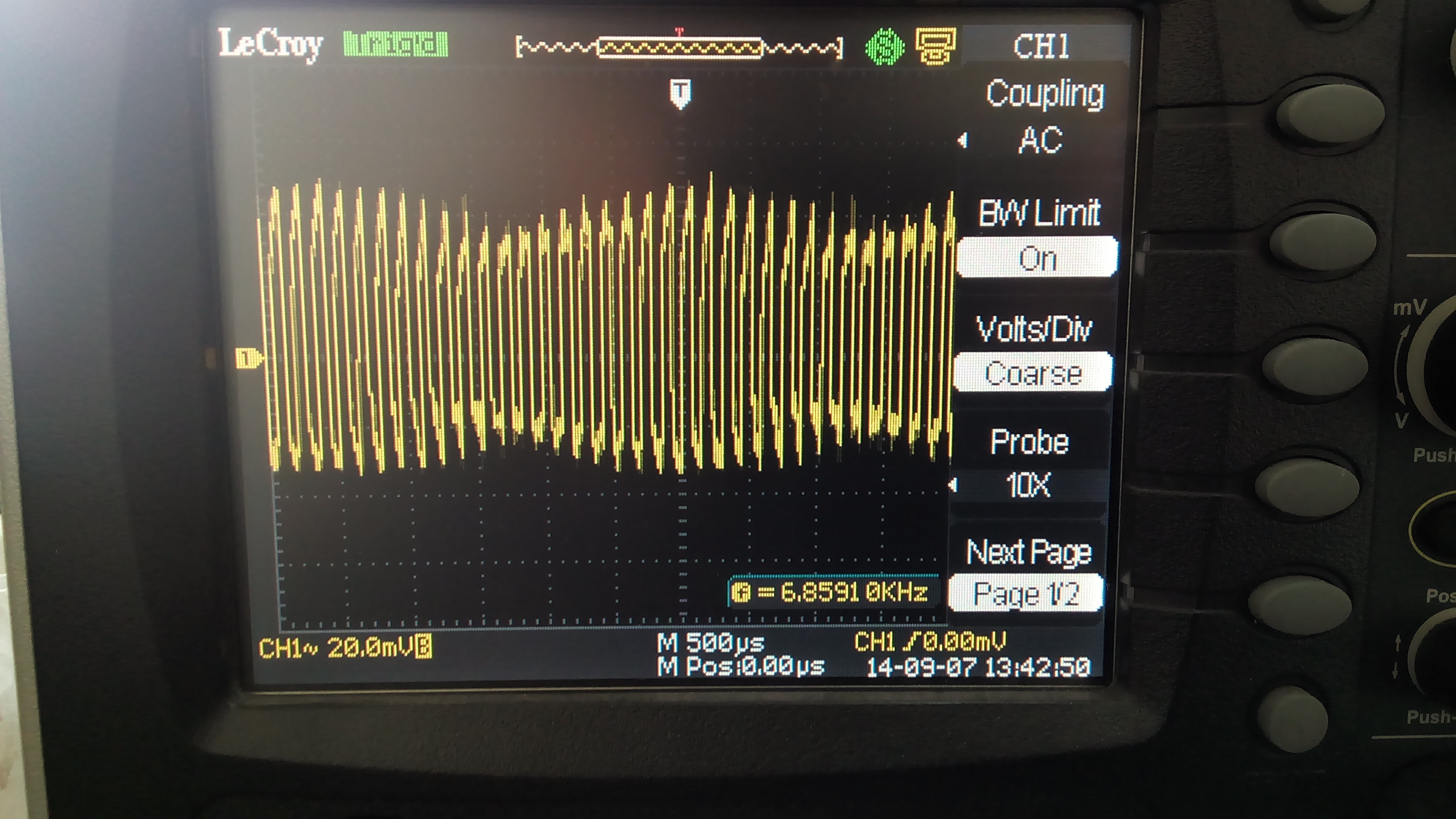
- LM324 was used to buffer a midpoint voltage(1.65) and fed to Vref input of MCP6S21 PGAs. This didn't work as expected in higher gain settings. The datasheet demands an output impedance of <0.1 ohms for Vref, although I'm not sure what caused the erratic behavior. Check out the following image of a 100mV sine wave amplified 32x. The PGA works fine up to 10x.
![]()
- The yellow trace is a mess! The other traces represent high impedance inputs that were floating, and probably accumulated charge which drained once the scope started digitizing them.
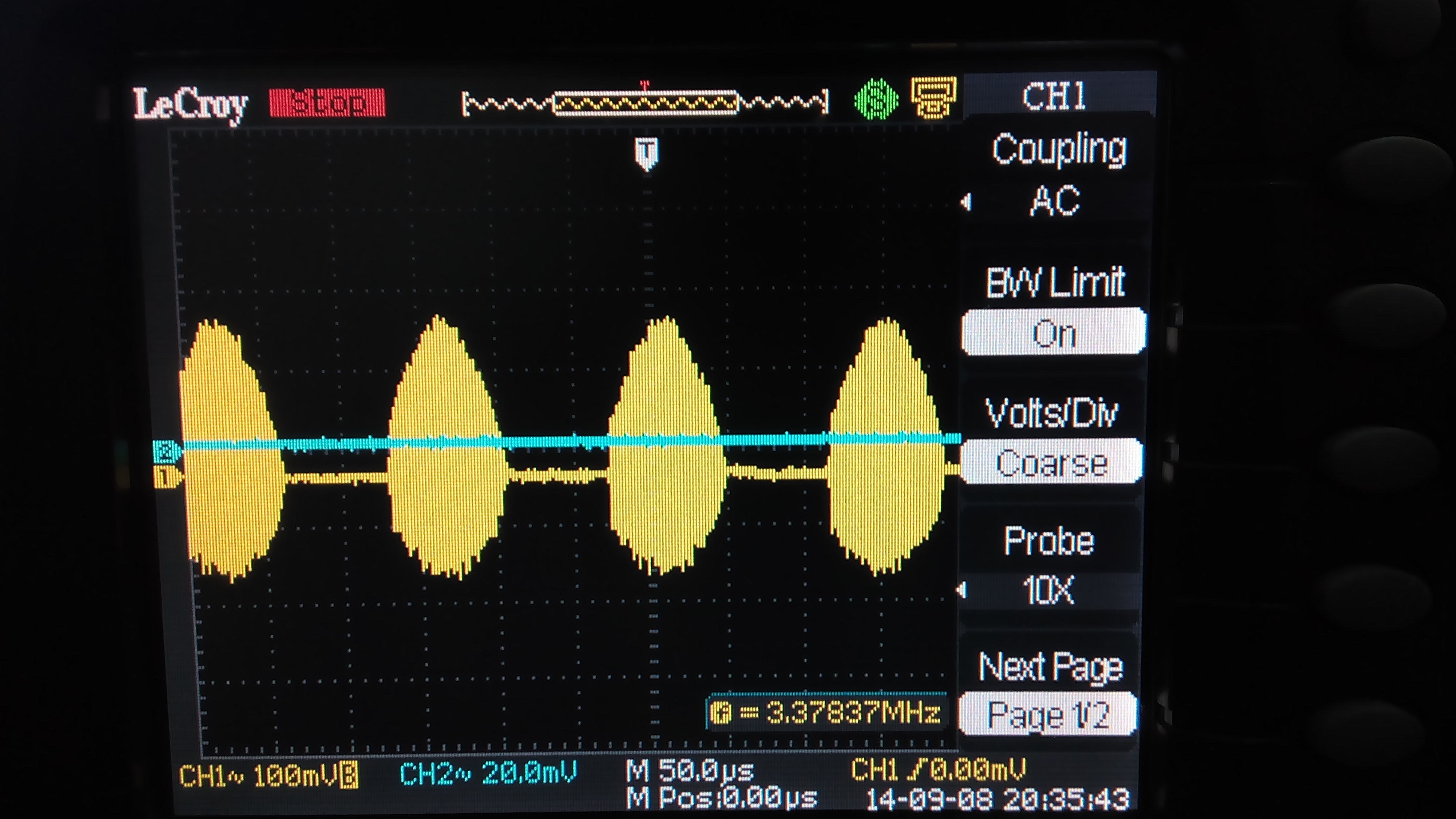
- I tried several possible solutions including disconnecting three PGAs and letting the LM324 drive the Vref of only one. But with no hope. Here's what the Vref pin looks like on a LeCroy scope.
![]()
- The LM324 simply cannot drive the Vref at high gain settings.
- Switching to a TL08 worked.
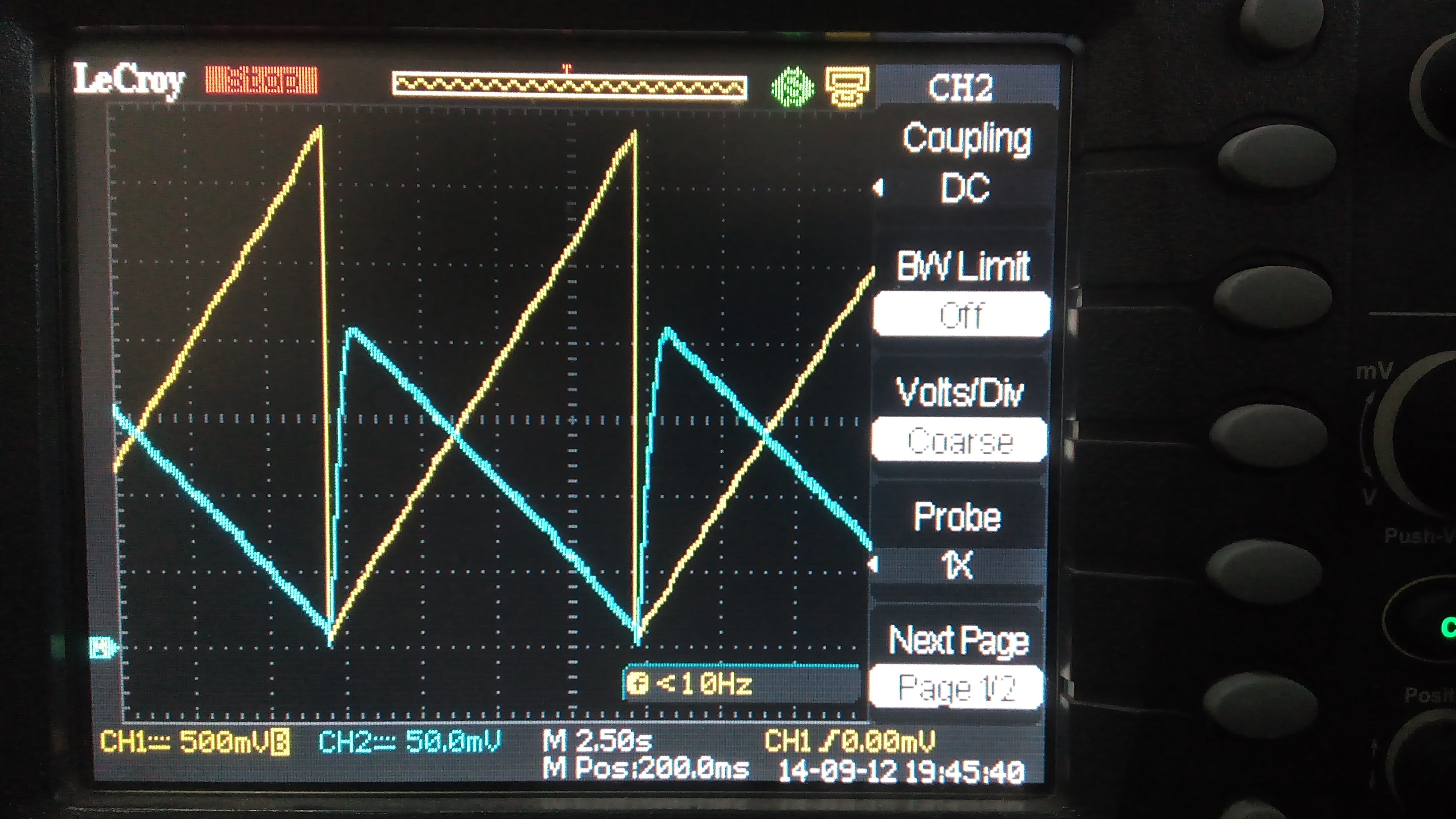
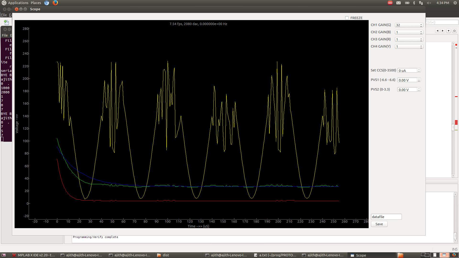
Yellow trace - DAC output to CCS circuit. Blue trace - Voltage drop across a 100 ohm load connected to CCS. The range of the constant current source is dependent on the load resistance since for higher loads, higher voltages need to provided to maintain the same current (I=V/R) , and there;s a limit to that.
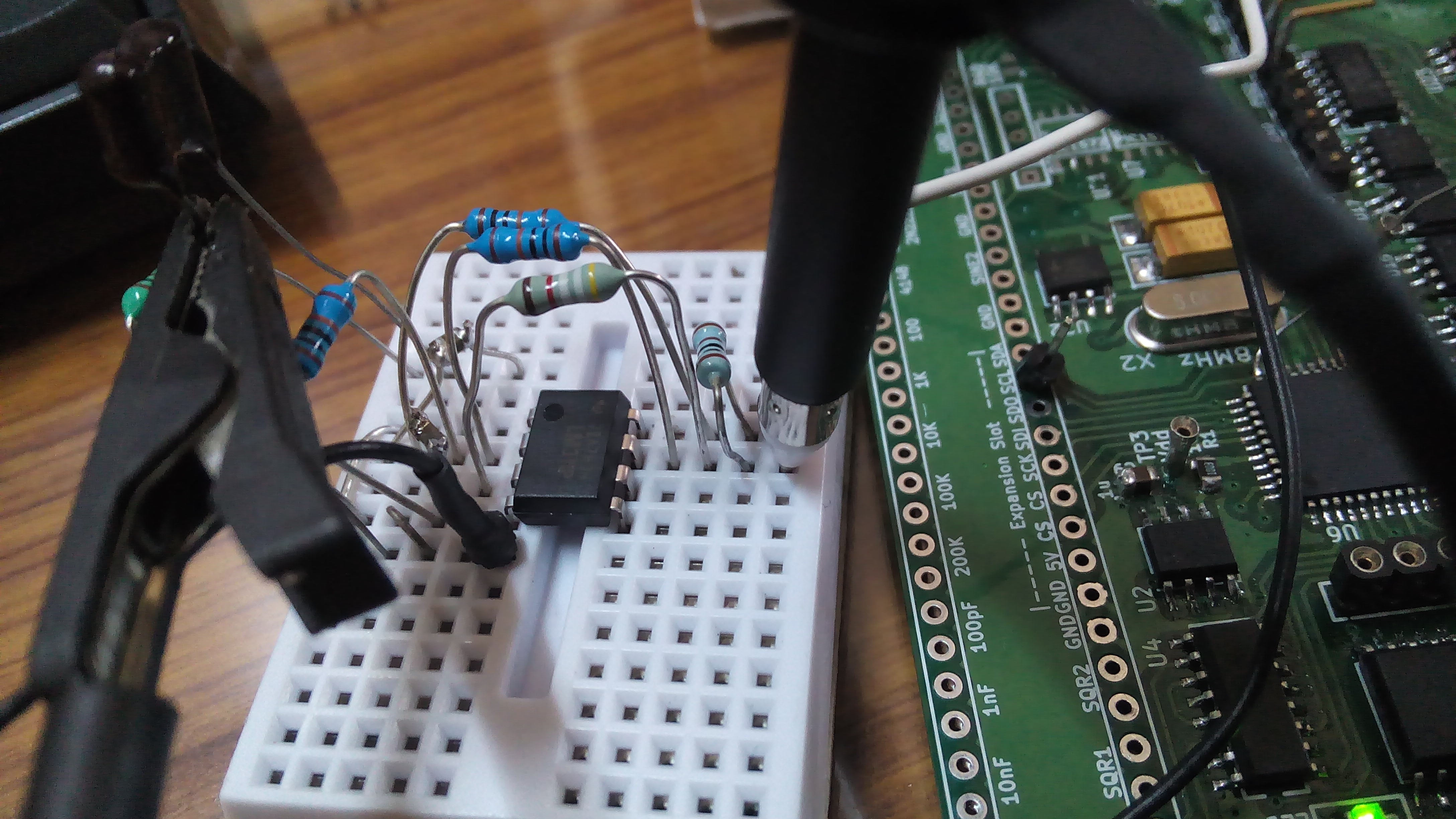
testing an LM311 based tank circuit driver to use as an inductance meter.
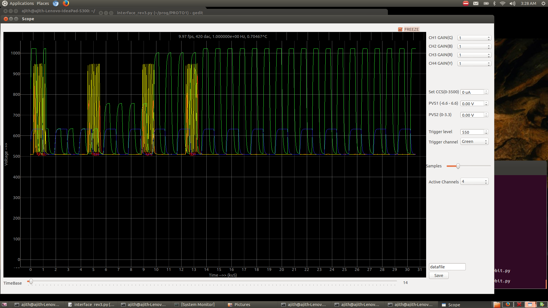
Verifying that other function calls can be executed while the oscilloscope runs in the background. In this instance, The yellow and red traces are looking at the SPI clock and data pins, while the green is a square wave connected to a PGA. The data sent over the SPI bus is actually changing the gain of that particular PGA. One can see that once the last clock of each packet is sent to the PGA, its output(green trace) changes.
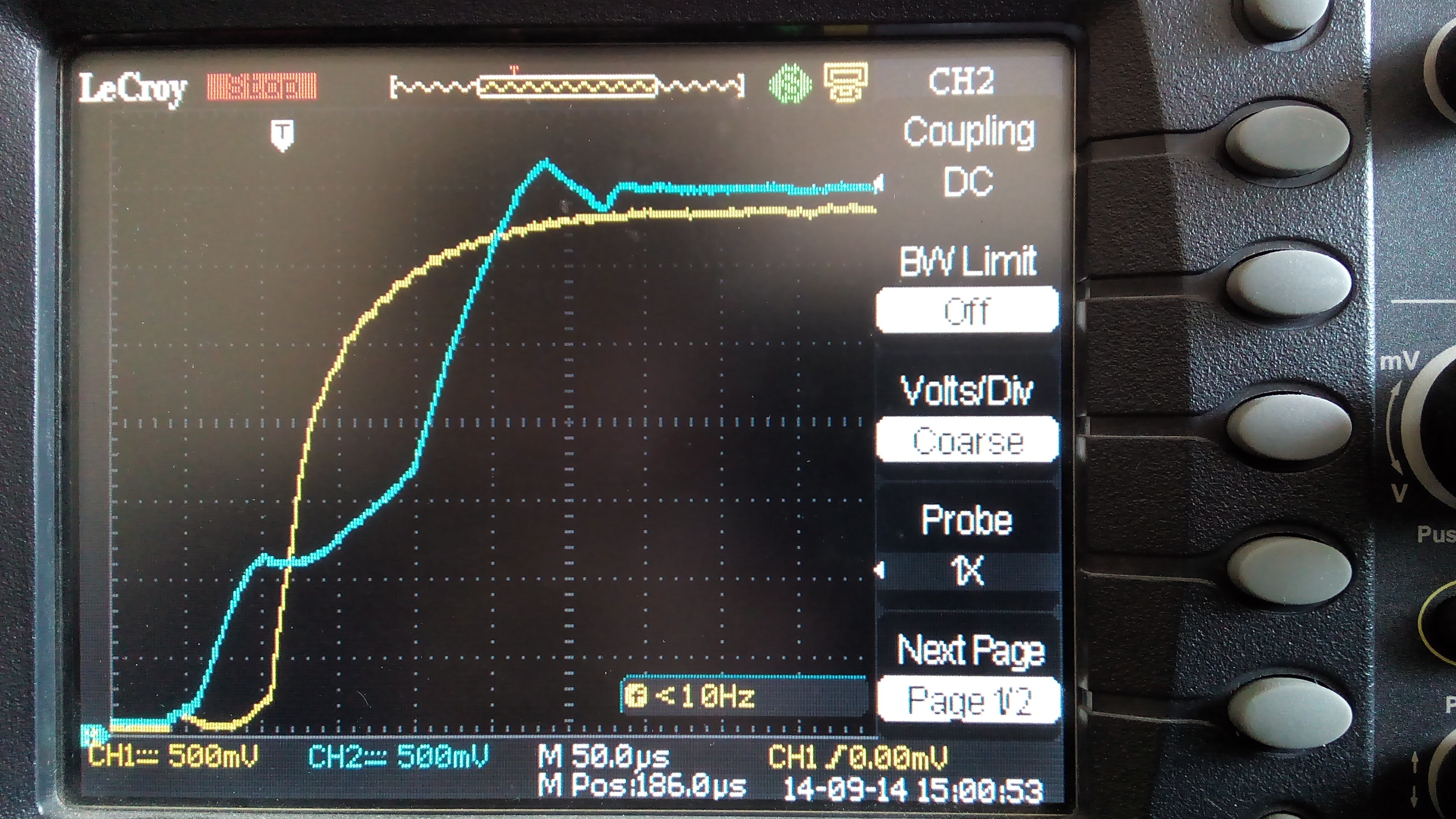
Vdd (Yellow) , AVdd (Blue) rising together since a diode was connected from Vdd to AVdd. No PIC oscillator failures have occured since.
Aluminium Capacitors can't seem to do the job for the charge pumps. They require low ESR Tantalum capacitors.
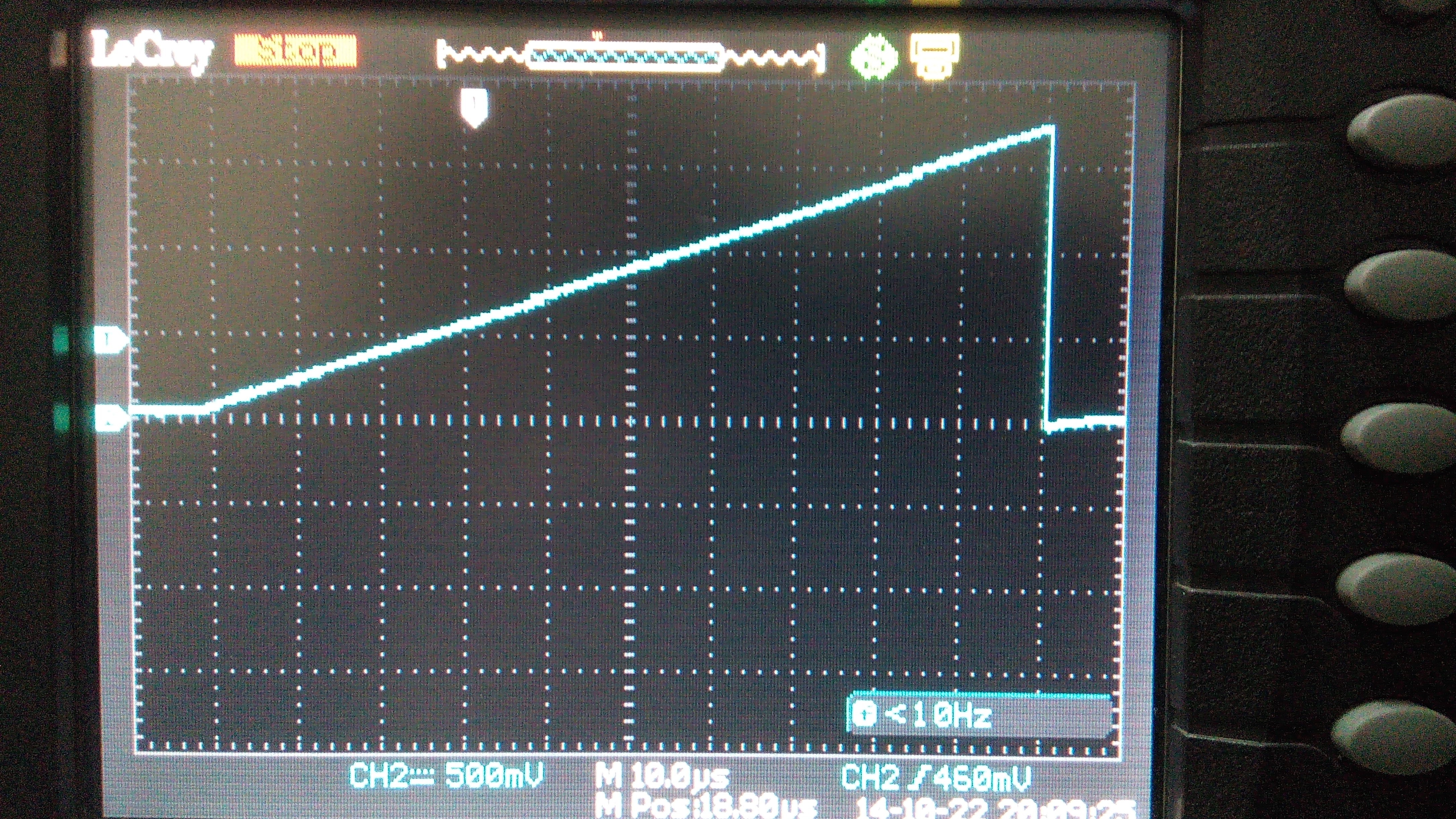
I monitored a capacitor's voltage while the CTMU was being used to estimate its capacitance using constant current charging. Q=CV => I*t = C*V [ Current, and charging time are both set by us. Voltage is measured at the end of the charging time, and therefore Capacitance can be calculated. ]
Monitoring this charging cycle using the LeCroy scope caused an increase of 13picoFarad in the measured capacitance. This value somehow tallies exactly with the 13pF capacitance specified on the LeCroy scope. No current source calibration was used.
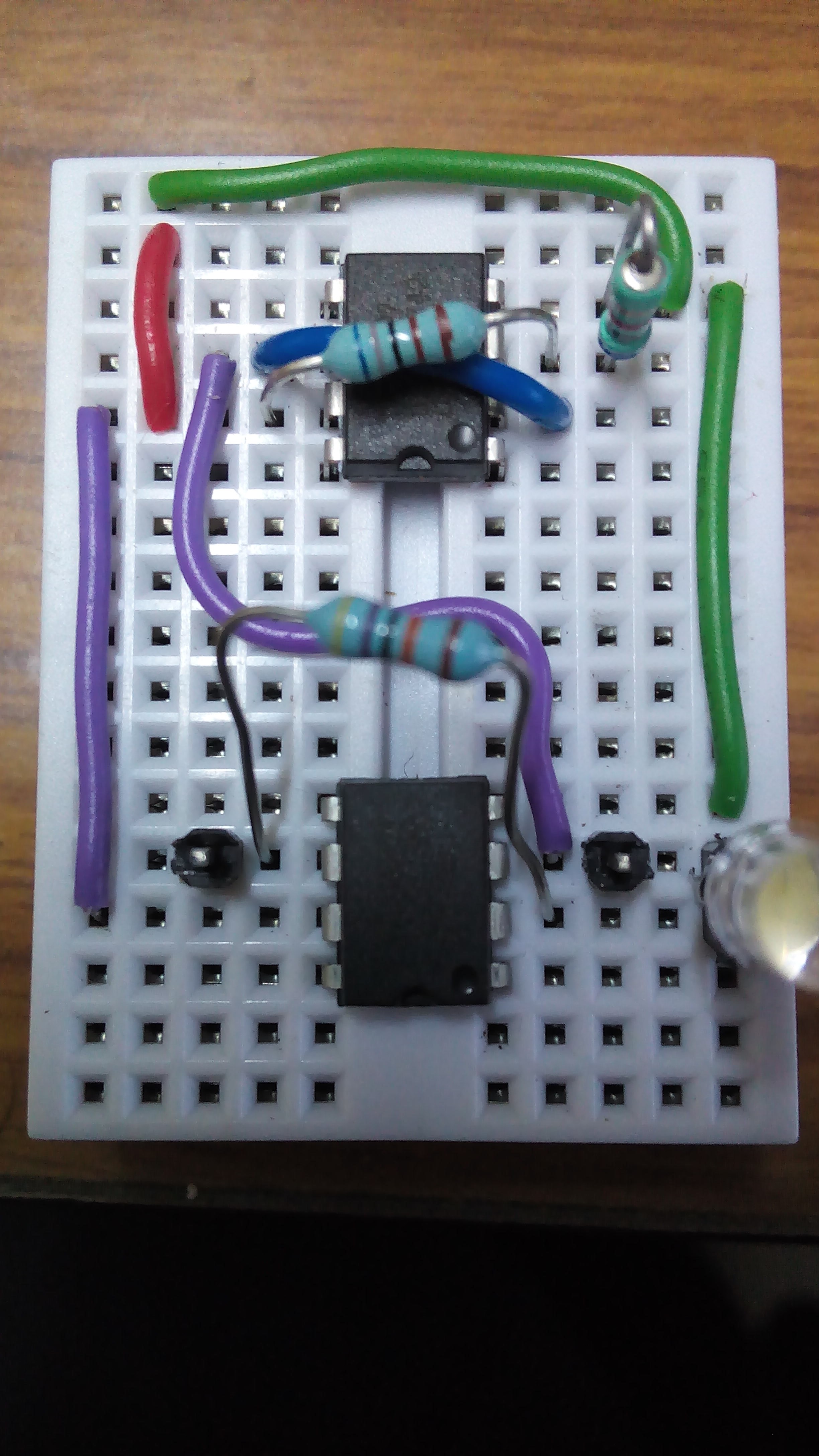
Trying out a NanoAmmeter. The LED is used as an input source, and the output from the ammeter goes up by a few mV when I shine a light source onto the LED
 Jithin
Discussions
Become a Hackaday.io Member
Create an account to leave a comment. Already have an account? Log In.