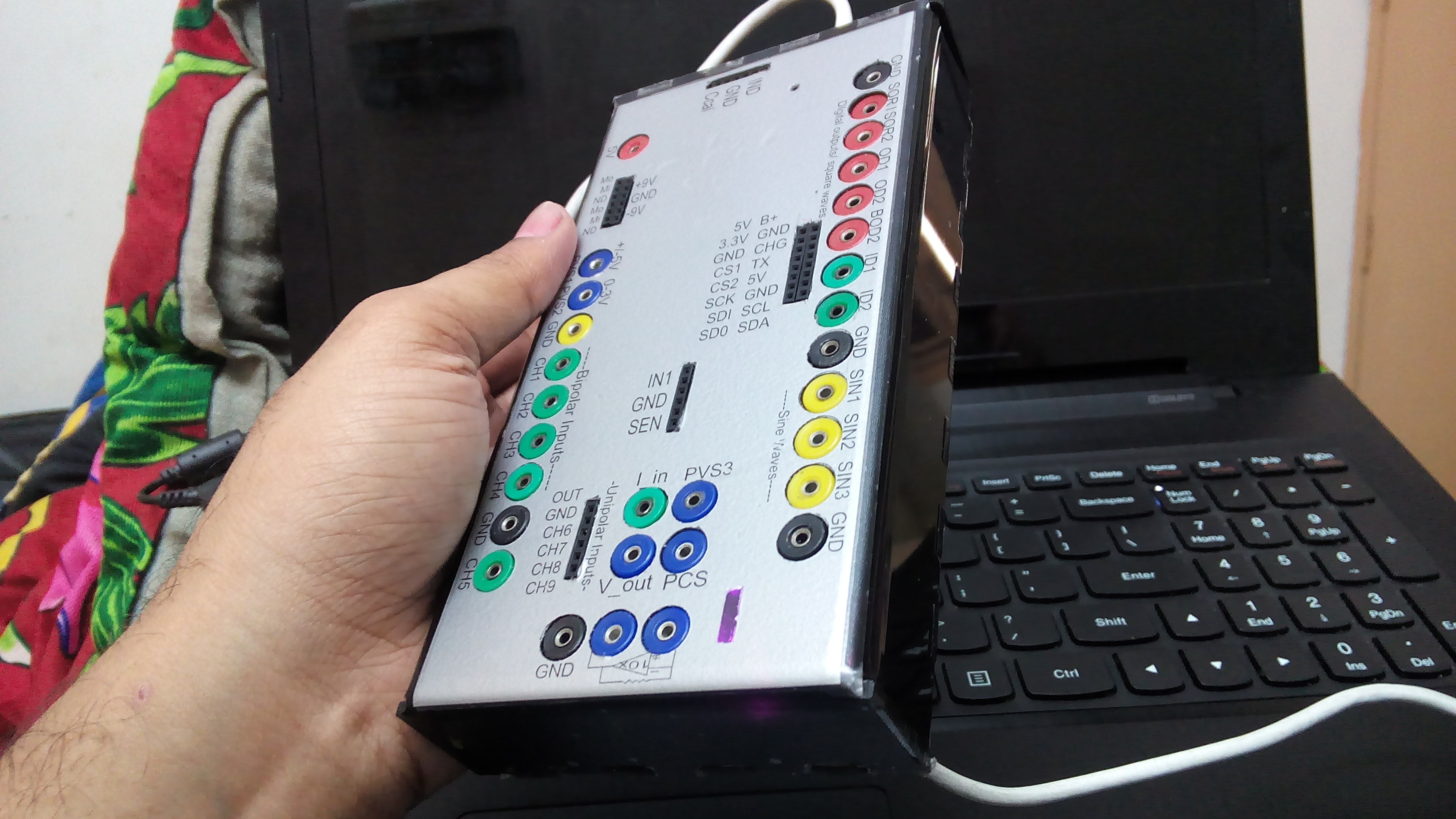
Moved to a larger form factor.
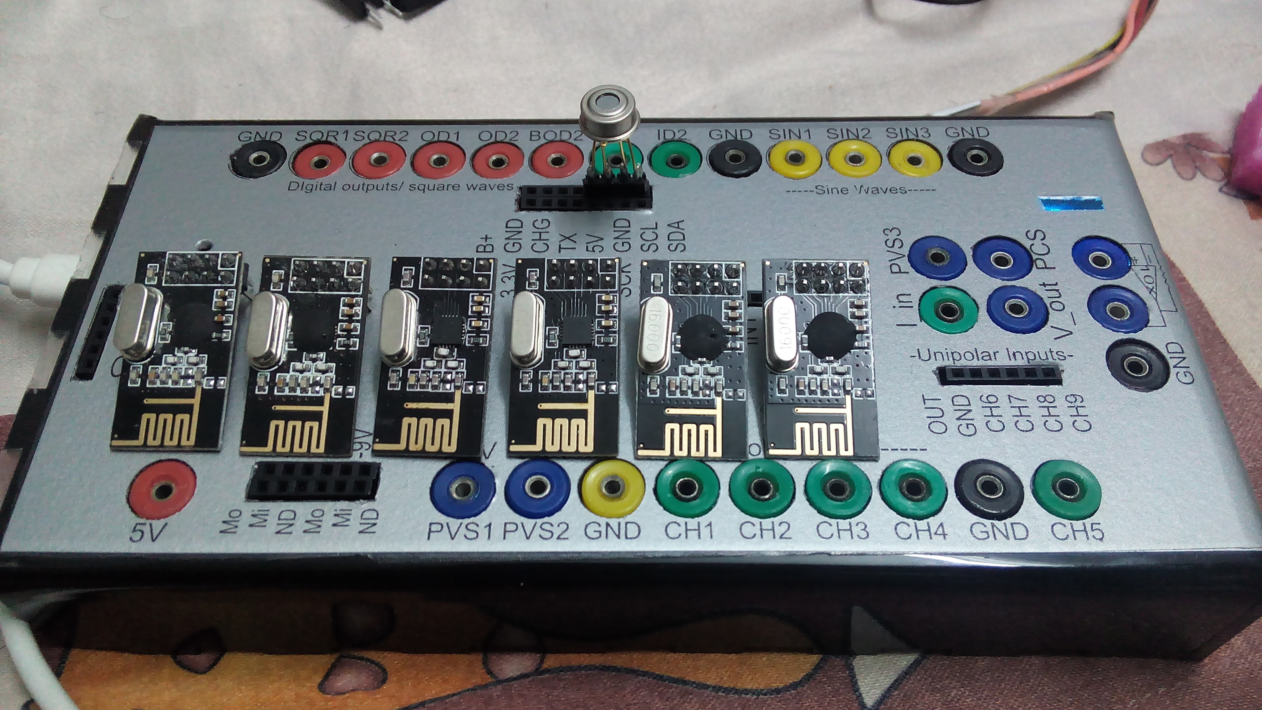
Replaced several crucial input connectors with banana sockets that are more reliable.
These include:
- CH1-CH5 - Oscilloscope inputs + 1 high impedance input
- ID1,ID2
- SQR1,SQR2,OD1,OD2
- I-V convertor
- Sine Wave generators
- PVS1 , PVS2, PVS3
- 5V, GND
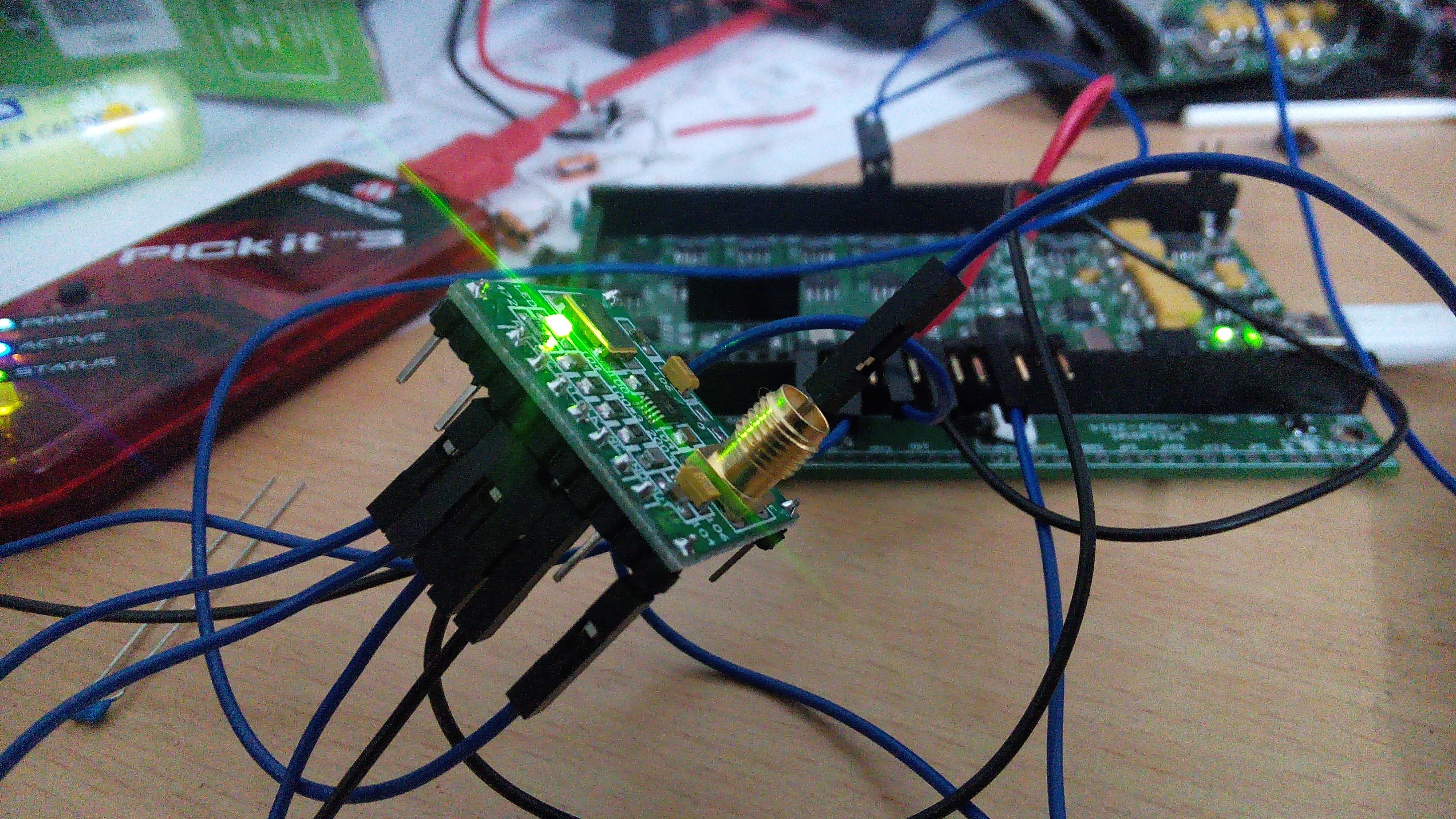
Included an AD9833 28-bit DDS in addition to the two phase correlated PIC1752 based wavegens.
This is the module I used for testing the AD9833 before including it on the main PCB
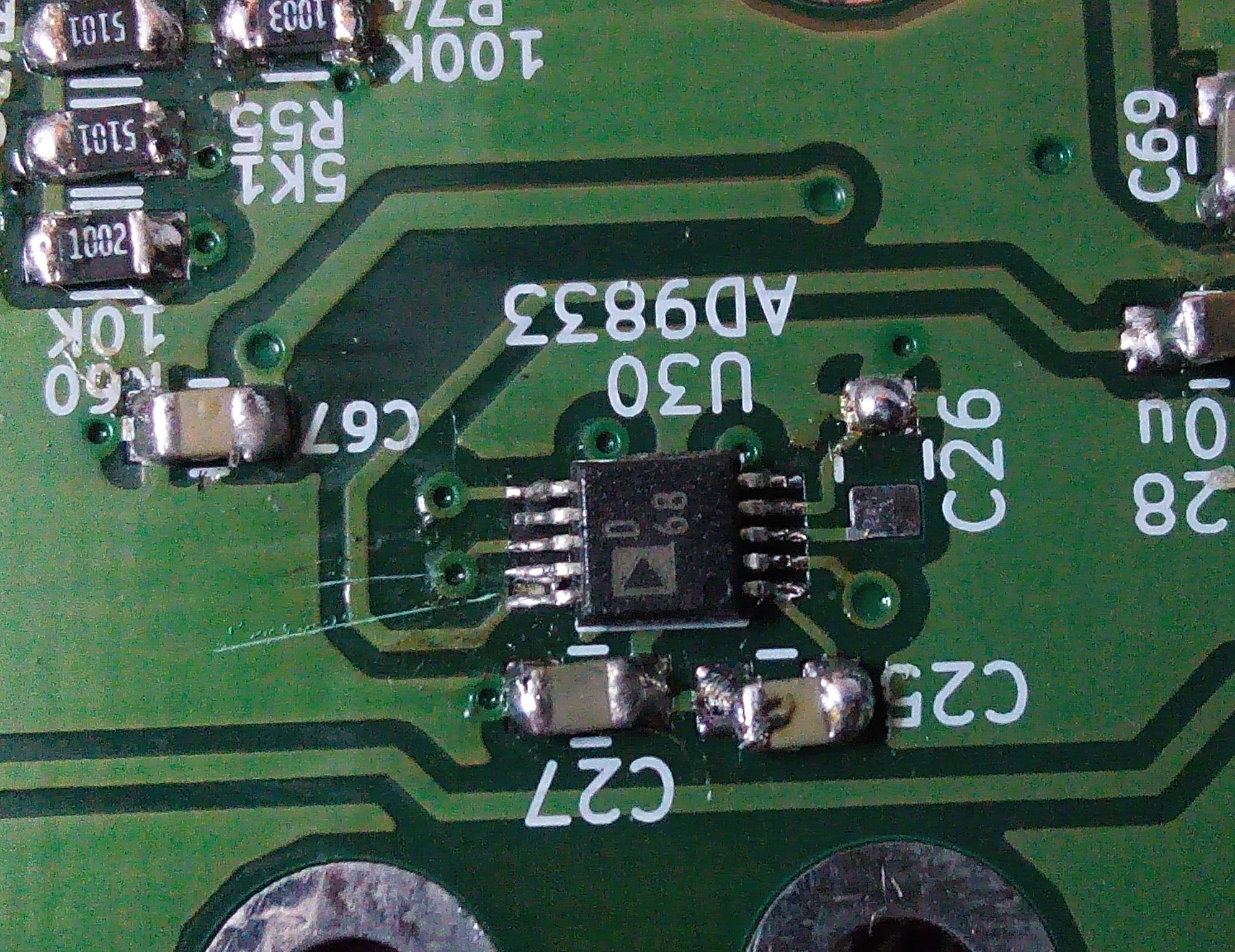
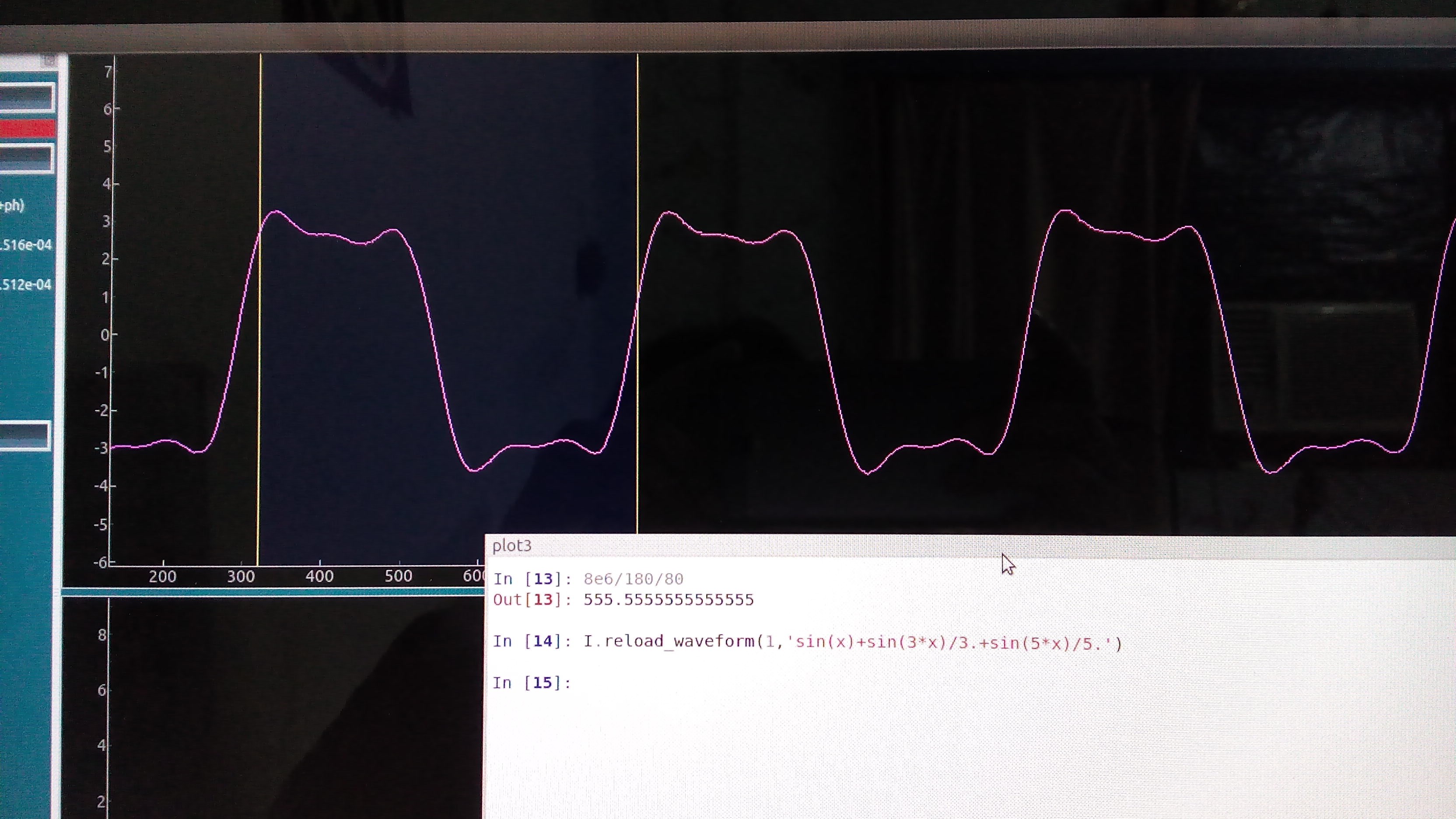
Since The PIC based wavegens use a a table I programmed, I added the ability to edit those tables in order to enable arbitrary waveforms. Subject to frequency response limitations.
The image below shows how easy it is to load arbitrary waveforms. Python accepts your function( In this case it;s the first three terms used to construct a square wave from sines ), and generates the corresponding table before loading it onto the PIC wavegen.
Sadly, the more powerful AD9833 is limited to sine, triangle and square waves.
NRF radios arrived. Looking forward to making wireless modules.
Visited several Laser cutting faciities to try out different enclosures for the prototype boards.
Will add a separate log for those
 Jithin
Discussions
Become a Hackaday.io Member
Create an account to leave a comment. Already have an account? Log In.