deʃhipu
-
New New Printed Circuit Board
08/01/2015 at 13:35 • 0 commentsYou know how it is. As soon as you get your hands on the new PCB and assemble another prototype to test it, you get a million ideas for improvements to it. That's what happened when I got the version 3 of the Tote's body, and it lead to a complete overhaul in version 4.
![]()
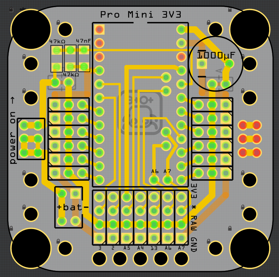
The most obvious change is the size. So far all the Tote's PCB were 38×38mm, simply because that size works well. But the servo horns stick out of the PCB quite far, so the robot is in fact bigger than that. Why not reclaim that space to have more room for all the components? Version 4 of the PCB is now 49×49mm, taking advantage of the maximum size of the board I can order cheaply. The spacing of legs is exactly the same, and there are holes there for the servo horns. That not only makes the whole construction a little bit more rigid, but also lets me attach the servo horns in parallel, instead of diagonally, reclaiming some of the precious space on the board, and making possible a host of other small improvements.
All components are now on a single side of the board, and the only traces that are on the bottom layer are ground. That means, that the whole bottom layer of the board is practically one huge ground fill. The switch and the battery plug are now located in easily accessible places. All the free pins are broken out in one large matrix, which also has easy access to ground, battery power and stabilized power, so that you can connect any sensors in there easily. I dropped the dedicated spot for an IR sensor, you just connect it on pin 2 as you would with any other sensor. That means that you will need to cross the sensor's legs again, unfortunately, though.
There is also a number of holes in the board for making it easier to add another board or to mount the sensors.
I'm still waiting for the board to arrive from the factory, I hope it will make it before the Hackaday Prize deadline. As soon as it arrives, I will make another prototype (I think I will have to disassemble one of the older ones for the servos).
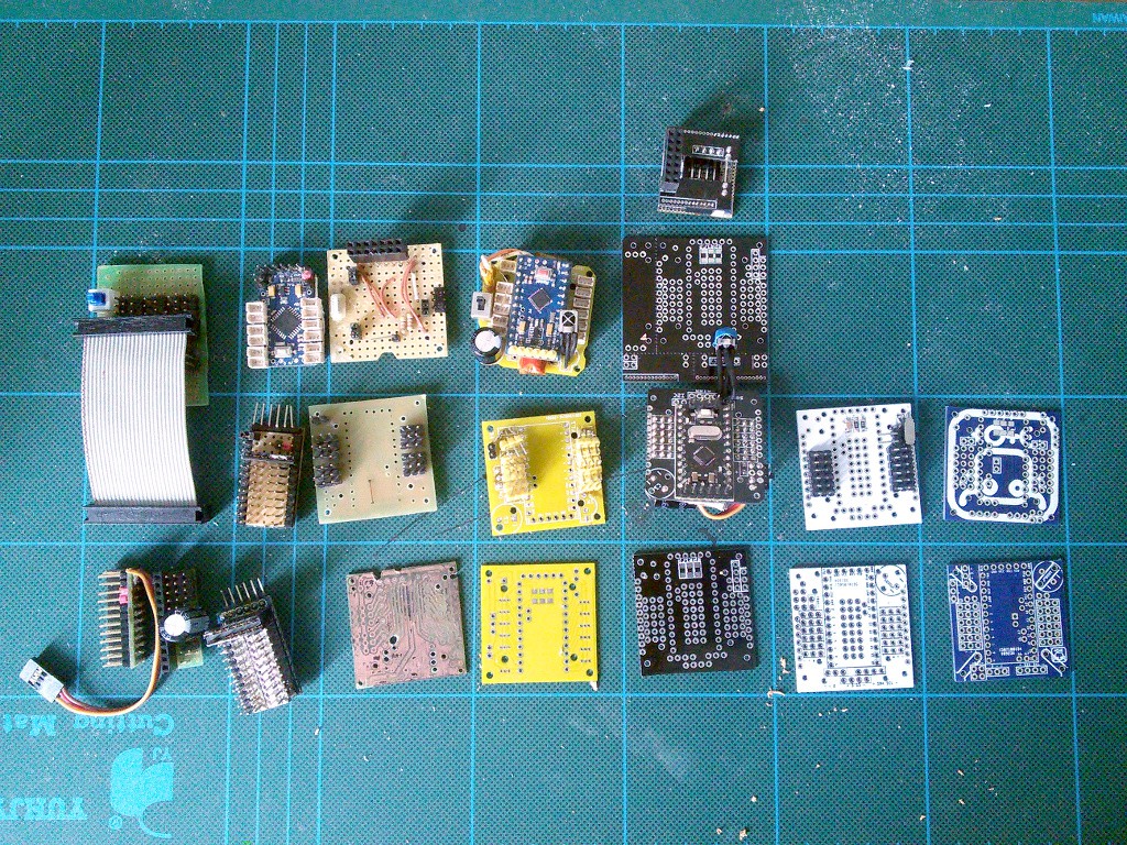
By the way, don't be fooled by a relatively low version number of this board! Before I started numbering them, there were lots of prototypes. I made a photo of most of the old boards that at some point were used in this robot:
That of course doesn't include the boards that are still sitting inside their robots.![]()
-
Follow Me, I Say!
07/30/2015 at 19:34 • 0 commentsI didn't have much time to work on Tote this week, but since the sensors arrived, I will at least finish the "follow me" log.
This time the sensors I got GP2Y0A60SZLF Pololu modules, which are specified to work from 2.7V. Hacks like the previous two attempts will sometimes work, but as you can see, often not, and you shouldn't rely on them.
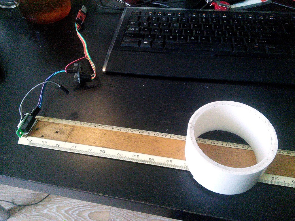
This sensor works beautifully though. Here's my testing rig:
![]()
And here are the results:
Distance Reading 50 20 45 68 40 122 35 174 30 243 25 317 20 423 15 597 10 900 5 1020 As you can see, they don't repeat and use pretty much all the scale from 0 to 1023. Perfect.
Now, let's just modify our program a little, using the new values for the readings:
void sharp_loop() {
    int distance = 0;
    for (unsigned char i=0; i<10; ++i) {
        distance += analogRead(A4);
    }
    distance /= 10;
    if (distance > 700) {
        creep_dx = 0;
        creep_dy = -1;
        creep_rotation = 0;
        beep(352, 100);
    } else if (distance > 520) {
        creep_dx = 0;
        creep_dy = 0;
        creep_rotation = 0;
    } else if (distance > 260) {
        creep_dx = 0;
        creep_dy = 1;
        creep_rotation = 0;
        beep(704, 100);
    } else {
        creep_dx = 0;
        creep_dy = 0;
        creep_rotation = PI/45;
        beep(1408, 100);
    }
}
And here we go:There still can be a lot of improvements. Instead of rotating in one direction, the robot could first just rotate its body left and right to see if the target is still there. I could use some timeouts between switching into the "search" mode, so that it doesn't switch back and forth constantly. The speed could be adjusted depending on the actual distance, etc. I will leave those as homework, though.
-
Follow Me!
07/24/2015 at 13:13 • 0 commentsSome time ago I got the Sharp distance sensor to work with Tote (somewhat), and I promised we will do something interesting with it. Obstacle avoidance is old, so let's try to make the robot follow us instead. The idea is actually very similar to obstacle avoidance, except that instead of avoiding obstacles, you go toward them.
So what's the plan? We want our robot to behave differently depending on what the distance sensor is telling it:
- If the obstacle is very close, go backwards;
- if the obstacle is close, stay in place and do nothing;
- if the obstacle is far, go forward;
- finally, if there is no obstacle in sight, rotate in place to find it.
This translates pretty easily into code:
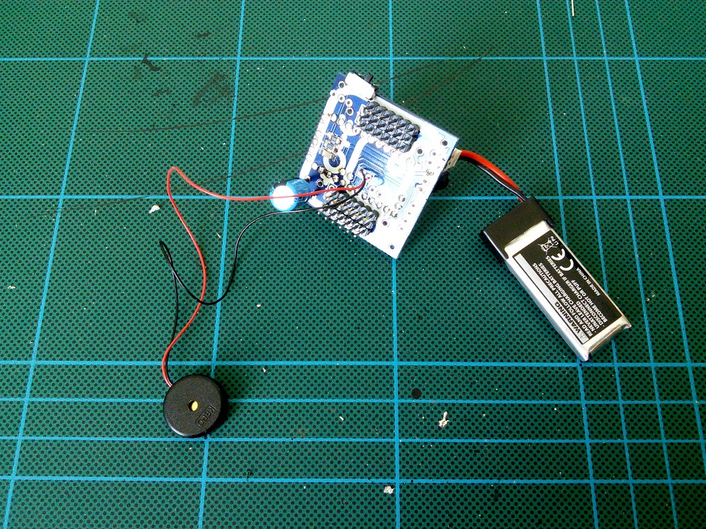
void sharp_loop() {
    int distance = analogRead(A4);
    if (distance > 660) {
        creep_dx = 0;
        creep_dy = -1;
        creep_rotation = 0;
        beep(352, 100);
    } else if (distance > 480) {
        creep_dx = 0;
        creep_dy = 0;
        creep_rotation = 0;
    } else if (distance > 420) {
        creep_dx = 0;
        creep_dy = 1;
        creep_rotation = 0;
        beep(704, 100);
    } else {
        creep_dx = 0;
        creep_dy = 0;
        creep_rotation = PI/45;
        beep(1408, 100);
    }
}
I also added some beeps in there, that will tell us what the current state is. Since the new PCB has a place for a piezo buzzer on pin 13, I also added it to the previous robots:
![]()
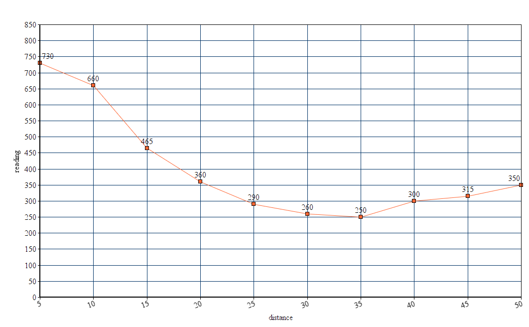
But how does our code work? Turns out, that it doesn't work very well. The problem comes from how our 5V sensor works when it's under-powered with 3.3V. Remember the plot of values from last time?
![]()
It's U-shaped, and that means that we get the same reading both for 20cm and for 50cm and more. That means that we have practically no way to tell if something is 20cm away or 50cm away, and that means that we can't reliably get the "no obstacle in sight" condition.
Even if we shorten our distances to where the curve is relatively straight, we are still going to get weird readings when nothing is that close.
Oh well, the sensor was cheap so it was worth a try. I guess this is a lesson: don't try to use parts outside of their specified parameters. Now I ordered some distance sensors that work between 2.7 and 5.5V, so that should be better. I will try again when they arrive.
Finally, a video of Tote failing to follow my hand:
-
Testing The New Printed Circuit Board
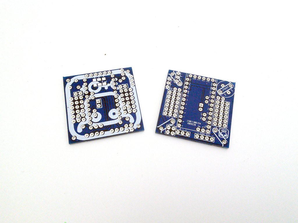
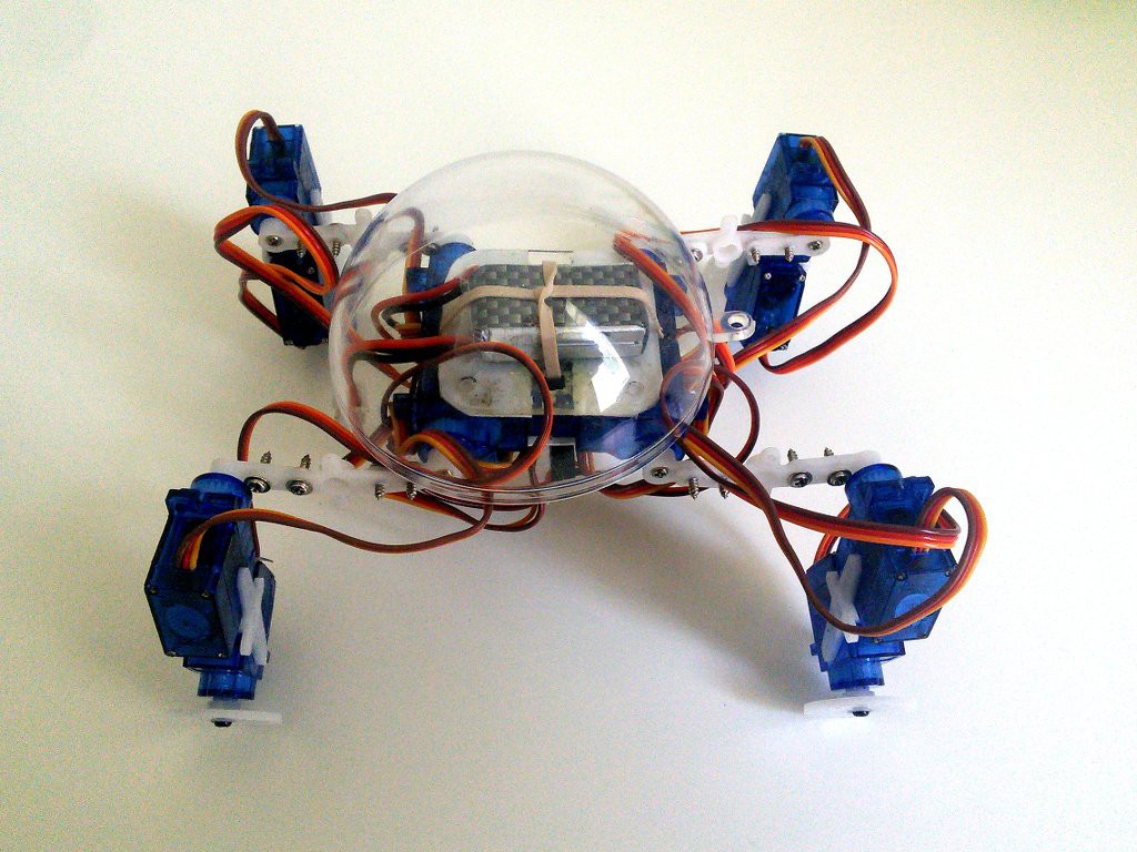
07/21/2015 at 14:44 • 0 commentsThe new PCBs just arrived from Dirtypcbs and I started to test them. This is version three of the board, and most of the improvements are really just for convenience or aesthetics.
![]()
So, this time there seem to be no errors on the board (last time I got boards with solder mask applied to some of the SMD pads). The picture doesn't really look as good as I hoped, but that's fine. Time to assemble the electronics and see if the robot works:
Along the way I also made a lot of photos, so I will probably be updating the assembly manual with them soon.![]()
Once I started to add the servomechanisms, I noticed that the mounting holes on the board are spaced wrong for the servo horns that I have. Strange. I compared them with the previous boards, and the holes are spaced the same. So it's the horns. Turns out that those cheap servos come with wildly varying horns, depending on where you order them and what batch they are from. I had to modify mine a little:
The next version of the PCB will definitely have to have the holes spaced a little bit farther apart, so as to be closer to the average for those horns. I think I will also make the holes a little bit larges, so that you don't have to use so much force when screwing in the screws. Lastly, while moving the battery connector was a good idea, the switch is still in an inconvenient place next to a leg. I wonder if I could place it better somehow.![]()
-
Cheap Chinese STM32 Boards
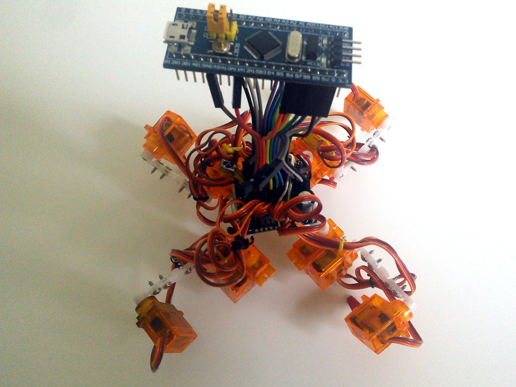
07/16/2015 at 16:23 • 0 commentsWe already saw that Tote can work with a Pro Mini, Pro Micro or Teensy 3.1 as its brains. The Teensy is especially interesting, as it gives us a lot of pins for additional sensors and effectors. But it's quite expensive. Could we maybe use a cheaper ARM board instead?
Turns out we can. Digging through my parts box, I found a "blue pill" board that I ordered some time ago from China for $4. It's an STM32 Cortex-m3 microcontroller on a relatively small development board. A little bigger than Teensy, but still compatible with the 600mil DIM sockets, so the same as the Pro Minis and Teensy. Of course, the pinout is not compatible, so I would need to make a custom board, or do the same trick I did with Teensy -- use wires to connect to the right pins.
![]()
But how do I program it? Do I need a JTAG programmer, a complex setup for cross-compiling to ARM and a complicated GDB configuration? Turns out that I don't, because there is the stm32duino project! And they even have a step-by-step YouTube video on how to program that board:
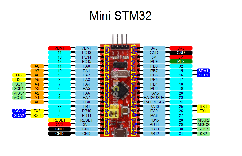
Turns out it's very simple and works like a charm. They also have the pinout of that board on their forum:
![]()
That should make it all much easier. Unfortunately, that pinout doesn't say which pins support PWM and thus are suitable for use with the Servo library. I had to get them by trial and error, which is what I spent the bulk of my time on. But ultimately I came up with a working set of pins, which I put in the servo.ino of the code that worked for Teensy 3.1. And it works. I will skip the video this time, because it looks exactly the same as the one with Teensy, so you can go and watch that one instead.
-
Custom Controller
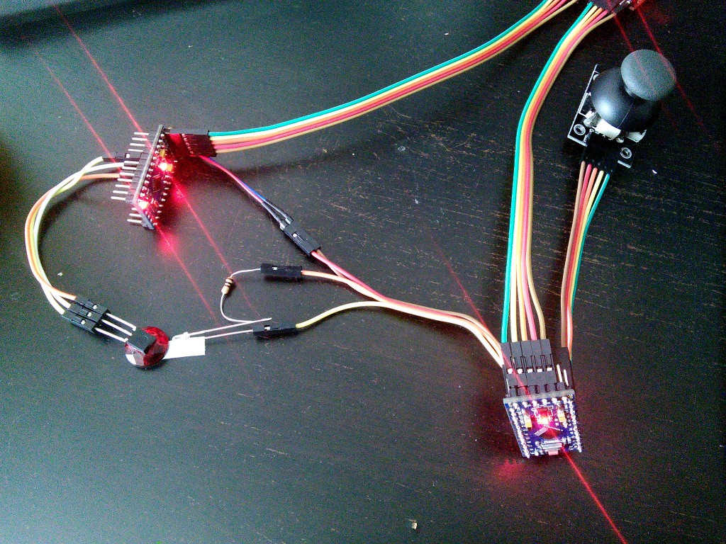
07/11/2015 at 15:49 • 3 commentsThe newest Hackaday Prize Hot List is about human interfaces, so I decided to work on that a little over the weekend. I found an analog joystick module lying around, so I'm going to try and make a custom controller for Tote.
![]()
First a quick test. The joystick has two pots for the position, and a button for pushing down the hat. That means we can have two modes, one for walking around, and one for changing the body posture. For a quick test, I connected it to a Pro Mini and tested with this simple Arduino sketch:
void setup() {
    Serial.begin(115200);
    pinMode(A0, INPUT);
    pinMode(A2, INPUT);
    pinMode(12, INPUT_PULLUP);
}

void loop() {
    Serial.print(analogRead(A0));
    Serial.print(", ");
    Serial.print(analogRead(A2));
    Serial.print(", ");
    Serial.println(digitalRead(12));
    delay(300);
}
It seems to be working perfectly. Next, I need an IR diode, for sending the signal to Tote. Quick rummaging through my parts box, and I found one, and a 100Ω resistor for it (the LED calculator says it should be 90Ω, but I couldn't find any).![]()
I also took another Pro Mini with an IR receiver and sample code to read the IR signals, for debugging. Now, my initial idea was to send the joystick position encoded as two bytes in the command (button code), and the state of the button would change the "address" part of the signal. Turns out it's not that simple.
The two bytes in the command code are not just arbitrary bytes. One has to be negation of the other. So effectively I only have one byte that I can send. So I decided to send two separate commands, with different addresses, one for the x, and one for the y. The code for that is quite simple:
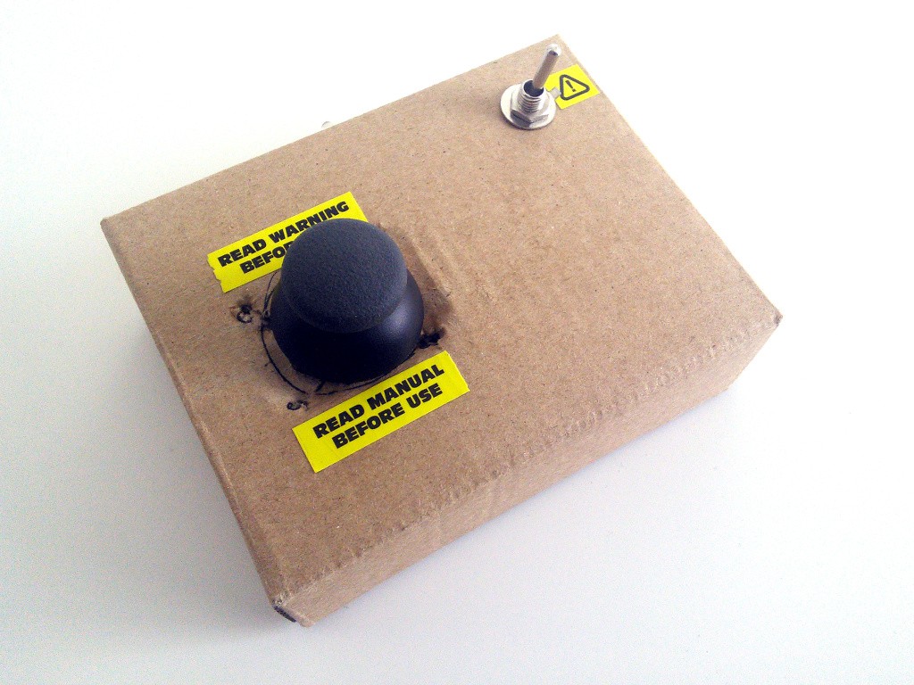
    switch (IRaddress) {
        case IR_ADDRESS:
            tv_remote(IRcommand);
            last = IRcommand;
            break;
        case 0xFA10:
            creep_dx = -(0.0 +
                         (IRcommand & 0xFF) - 128) / 42.5;
            break;
        case 0xFA00:
            creep_rotation = (0.0 +
                              (IRcommand & 0xFF) - 128) / 3652.605943958998;
            break;
        case 0xFA11:
            creep_height = min(TIBIA * 1.25,
                max(TIBIA * 0.25,
                    creep_height + (0.0 + (IRcommand & 0xFF) - 128) / 64));
            break;
        case 0xFA01:
            creep_dy = (0.0 + (IRcommand & 0xFF) - 128) / 42.5;
            break;
    }
Additionally, if the button on the joystick is pressed, you get different functions -- walking sideways and changing the robot height. All this added to ir.ino. All that was left was to put all the parts, together with a battery, in a box:
![]()
Some stickers taken from LiPo cells complete the look. Here's the controller in action:
-
Distance Sensor, Second Try
07/10/2015 at 19:18 • 0 commentsSeonsors are very important for robots, and a distance sensor is one of the most useful ones that you can install, as it gives the robot an approximation of vision. I tried to use an ultrasound distance sensor with Tote before, and failed miserably. This time I'm going to use an infra-red distance sensor.
The Sharp 2Y0A21 [pdf] sensor is probably one of the most popular hobby robot sensors out there, right after the ultrasonic one. But it takes 5V as the power supply. Will it work at our robot's 3.3V? Let's find out!
![]()
Connecting this sensor is easy. There are three cables: red for power, black for ground and yellow for the sensor output. The voltage on the output wire will vary depending on the distance being read by the sensor, so we have to connect it to an analog pin. The easiest way to use that sensor with Tote is to plug the wires into the I²C pin header, as both of the I²C pins of the Pro Mini are, by coincidence, also analog pins, and we have convenient 3.3V power and ground it there too. The photo above shows how to connect it.
Now, the first test. Does it even start when powered with 3.3V? There is an easy way to check any infra-red devices -- just look at them through a digital camera. The camera sensors are much more sensitive to infra-red light than our eyes, and will show you a shining LED. Test passed.
Next, let's try to get some readings and calibrate the sensor. I'm powering it with out-of-spec power, so anything written in the datasheet will most likely be completely wrong. We need to do our own calibration. We can do this with this extremely complex Arduino sketch:
void setup() {
    Serial.begin(115200);
    pinMode(A4, INPUT);
}

void loop() {
    Serial.println(analogRead(A4));
    delay(300);
}
It will basically repeatedly read the analog pin value and print it on the serial line. We can use the Arduino IDE's serial monitor to see those values. A quick test and yay, we are getting readings, and they are different depending on the distance. So far so good.
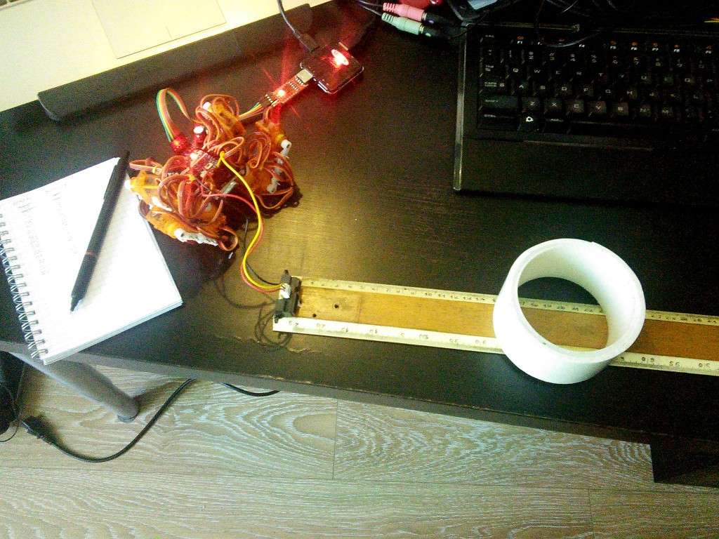
![]()
The photo above shows my testing rig. A long ruler, the sensor taped to one end, and a reasonably reflective white object. Note, that the power line from the USB2TTL is disconnected and the Pro Mini is running on the battery power, so that it gets to regulate its own 3.3V for the sensor, and doesn't rely on the power from the computer. Here are the measurements I did, plotted on a chart:
As you can see, the sensor has a much shorter useful range than the 80cm it gets on 5V. At about 35cm it starts to break already. But that's fine, 35cm is a lot for our robot. We also won't need exact measurements, so no need to convert those numbers to centimeters -- we will just read the chart for setting our limits.![]()
Next, let's actually attach the sensor to our robot and make it do something. Of course, the simplest thing it can do is to stop before it hits an obstacle.
I used adhesive tape to attach the sensor to the front of the robot. I might come up with a better way of doing it in the future, but this is good enough for now. Now let's add some code that does the stopping. We just add a sharp.ino file, with corresponding sharp.h, and call it all from start.ino. And let's see the results:![]()
It works as expected, the robot consistently stops at about 15cm from the obstacle. That's it for today, in the future I will show how to code a simple obstacle-avoiding algorithm, and then how to make the robot follow you around.
-
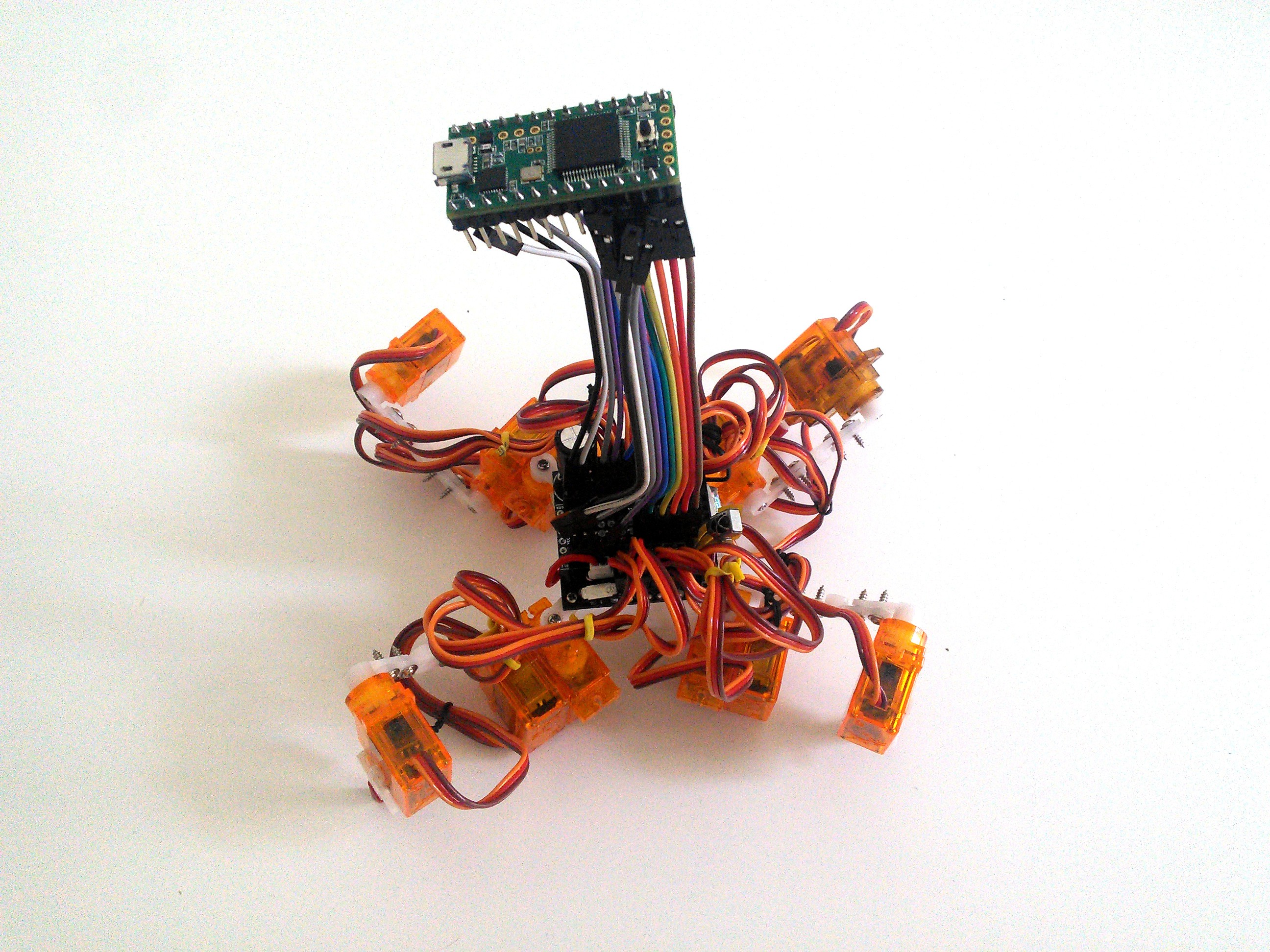
Logicoma-kun
07/07/2015 at 13:14 • 0 commentsThe continuous-rotation servos arrived, and I got to finish another of my experiments, which I mentioned previously over at the #Katka, a mammalian robot project. Since I'm re-using parts and experience between all those projects, it becomes harder to separate them. This one might even grow out into its own project, but for now I will publish it here, as it's basically Tote with a slightly different leg configuration and software.
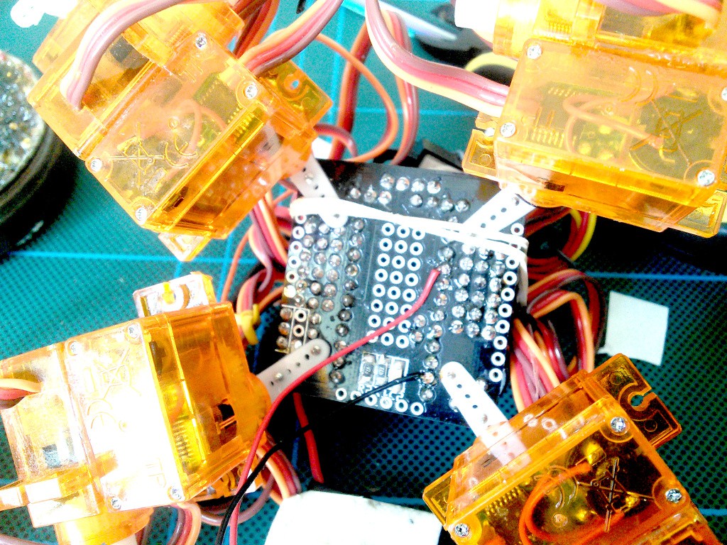
Remember the cute tank-robots from Masamune Shirow's mangas? First Fuchikomas, then Tachikomas. Now, in the newest TV series, there is a new addition to the family called Logicoma. And it's much more, hmm, shall I say "realistically", designed than the others -- in fact, I thought that I might be able to build a model of it out of Tote.
![]()
Since with the Arduino Pro Mini I'm limited to 12 servos, I had to find a way to reduce the number of servos and still get proper walking. My experiments with #Katka, a mammalian robot allowed me to do that, so I used the 4 free servo slots for 4 continuous-rotation servos placed at the ends of the legs. I could actually have converted the SG90 servos instead, but I didn't have the round servo horns for the wheels, so I decided to just order ready servos.
For now, just for testing, I have two separate programs, one for just driving forward:
And one for walking forward:
I'm sure I will be able to add a lot more, and also add all the props that will make it look like a real Logicoma, but that's it for a start.
I actually think that there is a lot of promise for this kind of hybrid robots that have both wheels for efficient and fast locomotion over flat terrain, and legs for getting through rough terrain, stairs, and maybe even climbing. If you look at the robots from this year's DARPA Robotics Challenge, many of them have additional wheels on them.
-
Using Teensy 3.1
07/02/2015 at 13:49 • 0 commentsOne of the topics I intend to cover in those logs is how to extend Tote with various boards and modules. I've already had one log on how to use Pro Micro instead of Pro Mini, and one on adding an ESP8266 board with Micropython. Now it's time for the Teensy 3.1.
The Teensy 3.1 is an ARM board very similar in shape to the Pro Mini, but with much more computing power and lots of pins, both digital and analog. It's really a great choice if you have outgrown the Pro Mini. You can program it just like Arduino, using the Teensyduino IDE. So I figured my code should just work, right? Wrong.
It actually took me almost 2 weeks to get my code to work. Here's the story.
Connecting the Teensy 3.1 is a little bit tricky. Although the pin pitch is right, you can't just plug it into the Pro Mini socket on the Tote, because the GND pin has been moved to the other side of the board. Sigh. That's fine, though, you can just use short wires, or, if you have a socket, a set of extra-long pin headers and some Dupont cables:
![]()
Then it simply plugs into the Tote socket. Looks a little bit weird, but should work just fine:
Now just adjust the pin numbers in servos.ino, remove the IR code (it's based on AVR interrupts, so probably won't work on Teensy), and we are ready to go. Another super-easy conversion.![]()
Except that it doesn't work. As soon as the robot is witched on, it gets an attack of epilepsy, twitching its legs randomly. Why? Why?
Now, the "fun" part of the project started. I began with the absolute low-level, checking first if the Servo library example works. It worked correctly. Then I proceeded to debug the servos.ino code, making sure that each servo really moves to the angle it has been told to move to. Everything seems to be in order. Hmph.
That means that the error must be somewhere in the inverse kinematics code. I was afraid of that. But the code works perfectly fine on the Pro Mini and other AVR-based Arduinos. So what could be wrong?
Someone told me that the abs() funtion may be not defined for floating point numbers, so I replaced it with a call to max(a, -a). No joy. Someone else told me that the AVR doesn't really have "double" type, and that it is in fact just normal "float". So I tried changing all types to "float". Nope. Then changing all the trigonometric functions to their float versions. No. Verifying all loops for buffer overruns and adding sentinel conditions checking for correct ranges. Still nothing.
Finally, the time has come to disconnect the Teensy 3.1 from Tote and do some serious debugging over the serial. After placing a lot of strategically planned print statements, a pattern started to emerge. It seemed that sometimes a value would suddenly be multiplied by 255. How come? Add more print statement to also display the constants and tables I used, and I found the problem.
Turns out that the char type is unsigned by default on ARM. And I had some tables with just values like 1 and -1 for tuning various parameters. And of course all those -1s have become 255s, and the robot went crazy.
After replacing the chars with ints, everything went more or less smoothly:
Remember kids, don't write "char" when you mean "int8"!
-
Schematics
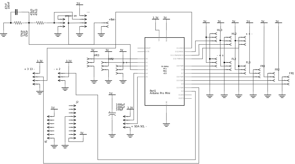
06/30/2015 at 15:58 • 0 commentsI've been asked to provide schematics of the PCB. I must admit, that I neglected that part a little, mostly doing all modifications and connections directly in the PCB view, but now I cleaned up the schematic view a little better.
Here's the schematic for PCB2 (the ones I've been giving out and which you can order from dirtypcbs):
![]()
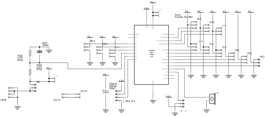
And here is the reworked PCB3, which will be available soon (I need to order and test it first):
![]()
As you can see, there isn't really much to it, it's mostly connections for all the servos and the small voltage divider for battery monitoring.