Roeland54
-
The code is online, demo of stereovision
04/28/2014 at 18:09 • 0 commentsSo first of all you can find the c# code of the project here:
https://bitbucket.org/rlutters/hack-a-day-sci-fi-contest
We also have a demo video for the stereovision: -
Putting in the stereovision
04/28/2014 at 14:55 • 0 commentsSo for the last part we needed a way to get an x,y,z coordinate. We had some idea's how but we ended with Stereo vision.
With just 2 motes we could calculate an x,y,z coordinate, since 2 lines in space intersect only trough one point.
This seemed to work great, we could track the copter easily when moved him slow, but when we triend it with the flying copter we saw that the motes where sometimes giving incorrect values causing our copter to crash.![]()
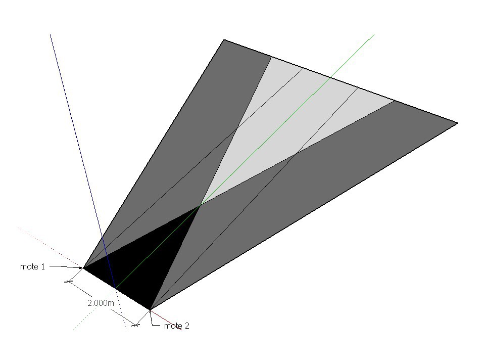
With stereo vision there are 4 zones:
- First is outside everyones range, you don't want to be there
- Seccond is the blind spot (marked black). Like the first, you don't want to be there.
- Third is the gray area. This is the field where you are seen by only one mote. This could be used to get you back to forth place, since we have a clue of where you are.
- Last is the light gray area, this is where we have stereo vision.Since the motes are on one line we can say that the y value are the same, practical we take the average.
For the z and x value we use the x value off the motes and draw a mental line between the mote center and the point they see.
Those two lines intersect eachother and that intersection is our x and z value. -
2 axis control tested (video)
04/25/2014 at 14:58 • 0 commentsAfter some fine tuning of the PID's we could finally do some test with 2 axis control by the computer.
but first something about the progress of connecting everything.
![]()
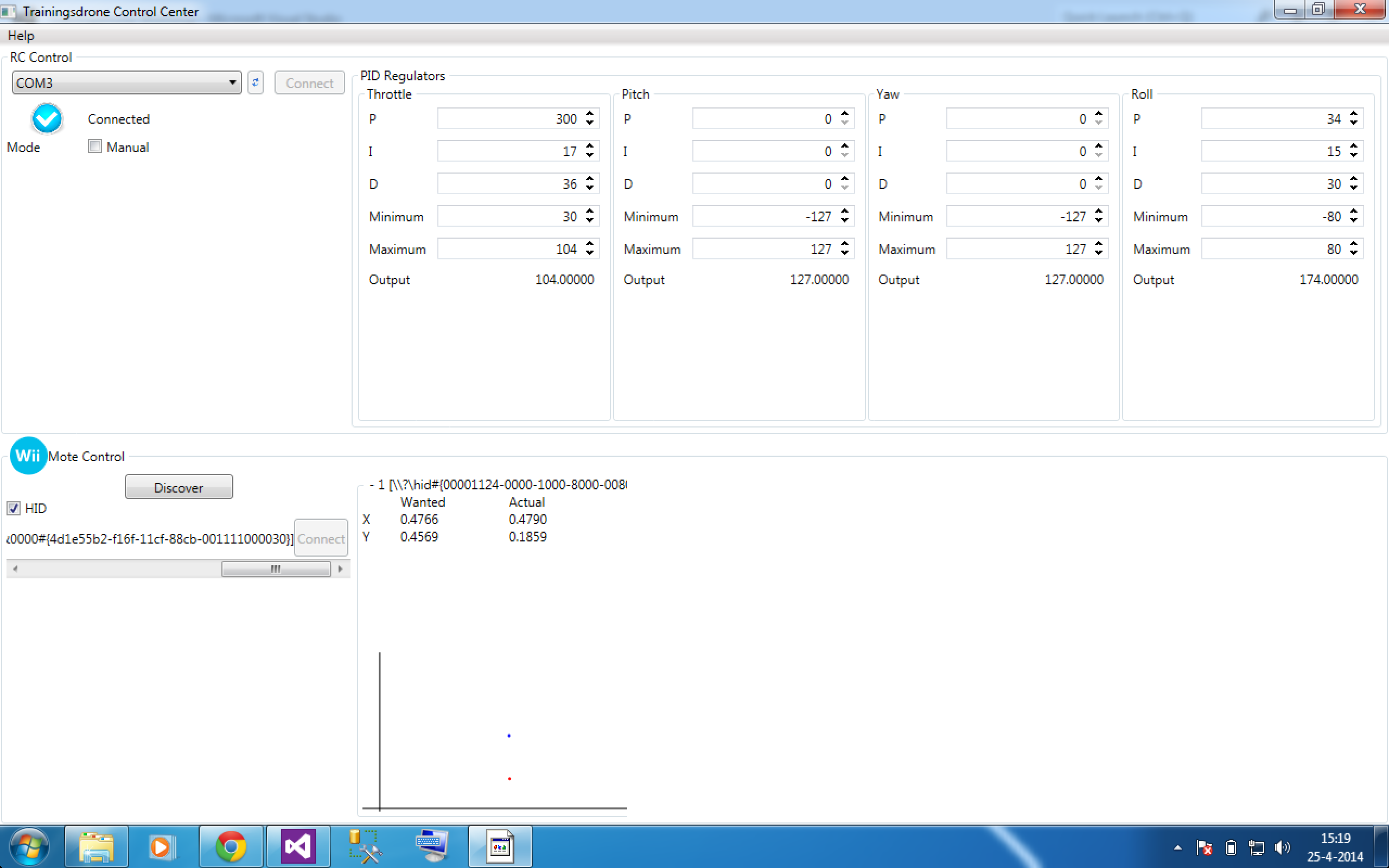
1. connect the available WiiMotes.
you can connect a WiiMote in windows 7 by just using the standard windows bluetooth wizard. It creates a new HID device in you device list. So at the left lower corner of our application you can search for available WiiMote's. Once there is a WiiMote connected you get the 2-axis representation of de the detected IR-lightsource on the right (the red dot). You also can put the wanted location on de grid by clicking it (the blue dot).
2. Connect to the RCremote.
On the left upper corner there is the connection panel to connect to the arduino that sends the pwm signal to the rc-remote.
3. adjusting pid gain value's
you can adjust the PID gains and min, max values realtime with the text boxes. The current output is also visible (value between 0 and 255).
So with 1 WiiMote we can determine the position of the quadcopter in 2-axis.
the other axes can still be controlled by the RC remote in the classic way.Time for a little demo:
Wat is happening here is that the computer is adjusting the throttle (height) and the roll. (the orange propellers are the front.)
you can see the throttle adjustment is working already wel. The roll still needs some adjustment. -
Flight Test
04/24/2014 at 06:39 • 0 commentsLast monday we did our very first flight test in order to tune the PID control.
During the tests we let our program control the throttle of our quadcopter and made it fly up to a given height.
The tests proved that the PID control needs good finetuning for a good control over the quadcopter.
Here are some video's of our test flights:
- Flight Test 1: https://db.tt/V37vhwtB
- Flight Test 2: https://db.tt/Q9SC3ysT
- Flight Test 1: https://db.tt/V37vhwtB
-
Bug fixing, bug fixing and OH IT WORKS
04/18/2014 at 07:30 • 0 commentsWell at least in theory... https://www.dropbox.com/s/hg650wtnxxq2ws1/Capture.avi
In the screen capture you can see the PID in action after I moved the targeted point, if i put the target point back to the corner (0,0) then it starts to descend again. Now we wait for test flight 2 on monday. Fingers crossed.
-
Attempt one on flight
04/15/2014 at 07:11 • 0 commentsThis saterday we tried to get flight... Well that didn't work out.
We had some issue but after 4 hours looking at the problem we didn't see it. Luckely it is quite testable so this week we will have an update.
-
Creating a GUI
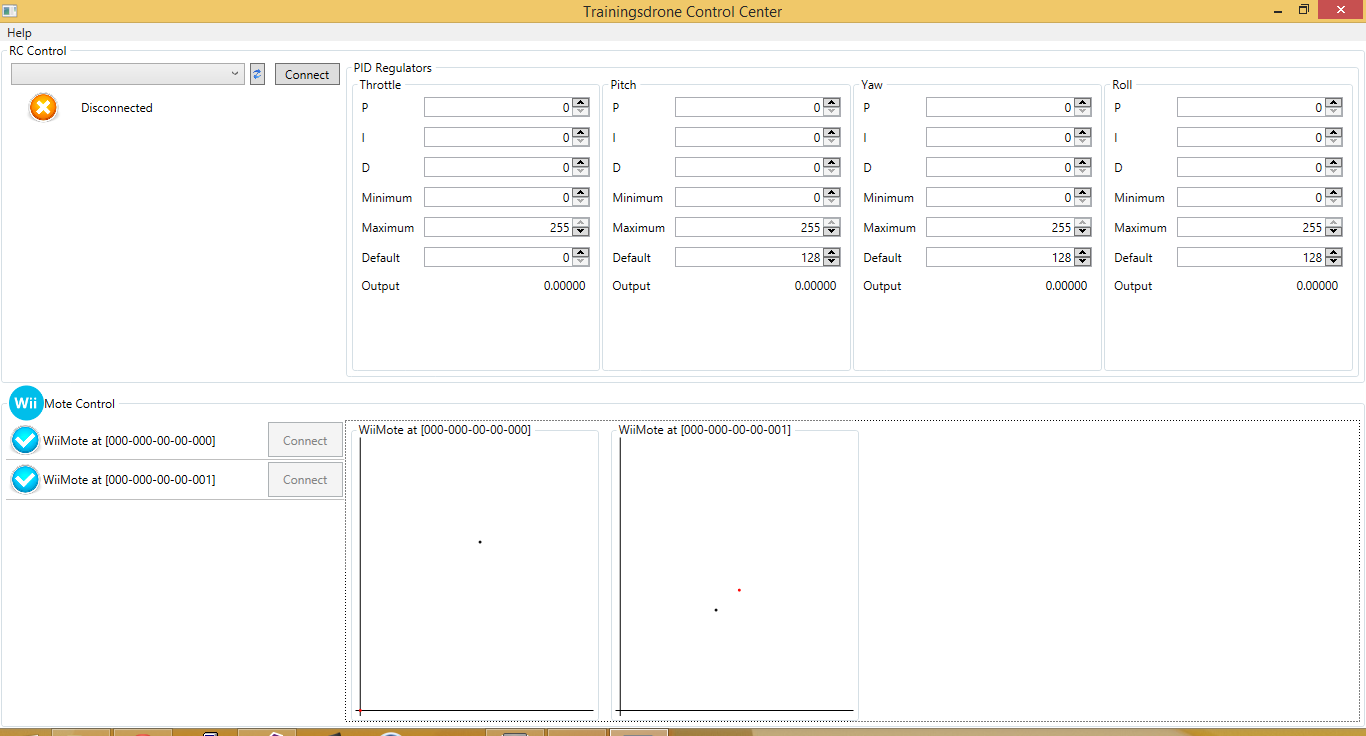
04/10/2014 at 19:58 • 0 commentsI proudly
present the UI version 1: ![]()
In it we have RC control on top and on the bottom the feedback from the wiimote (no real wiimotes where hurt during the making off)
Next step now is connecting the GUI to the code writting by
colleagues, I hope we get it ready by saterday for our first flight test. -
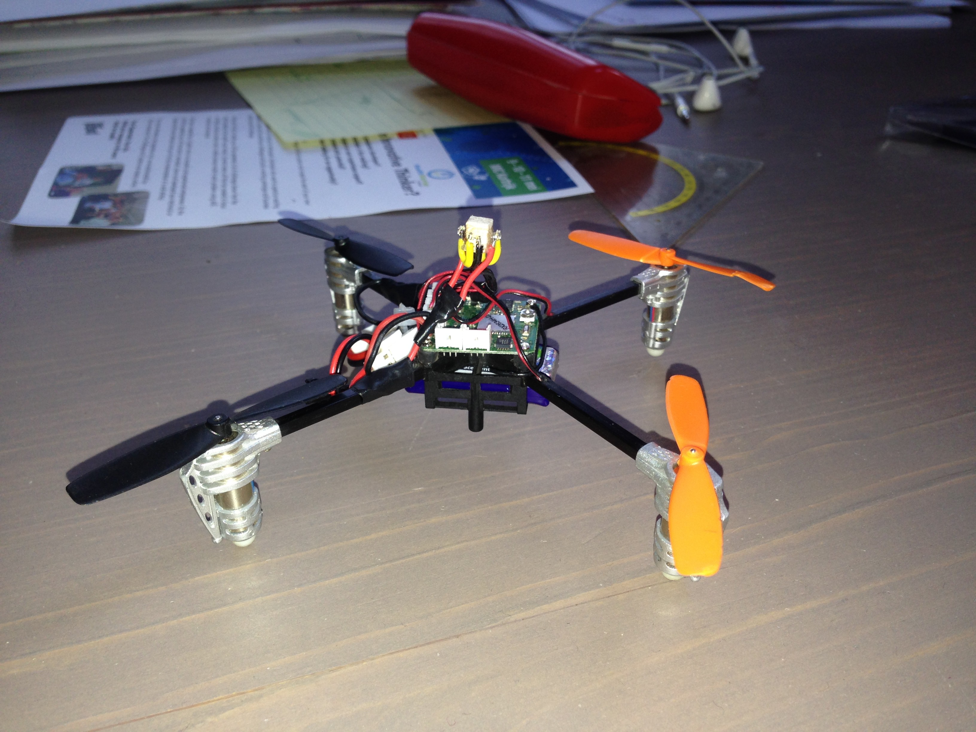
Making the quadcopter visible for the wiimote
04/09/2014 at 20:23 • 0 commentsTo make it possible for the wiimotes to see the quadcopter. We added some IR-emitting diodes. To make sure the quad is visible in different angles. I searched led's with the biggest radiation angle. The maximum angle of normal IR's LED's is 100°. But you can find SMD led's with 140°. So I ordered some SMD's . The wavelength is 940nm because the wiimote is the most sensitive to 940nm.
They are so small it is hard to see them! :p
![]()
-
3D position from wiimote signals
04/08/2014 at 20:49 • 0 commentsAs it turns out, it requires some long-forgotten math skills (and patience!) to get a 3D-position from the wiimote outputs. I started with a 2D position determination.
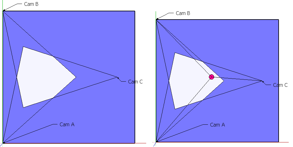
Below you see the top view of our setup. Cam A to C represent the three wiimotes, each with their FOV. The 3 FOVs overlap in the pale blue part, this will be our field of action. Each wiimote returns an x-value between 0 and 1, the horizontal relative position of the quad in the wiimote's FOV. When the quad would be positioned on the red dot, the wiimotes would return e.g. 0.8 (camA), 0.1 (camB), 0.6 (camC).
![]()
Of course we have to work the other way around. The quad is positioned in the field somewhere and we get 3 x-values from the wiimotes. I almost finished the calculations to determine the quad's x,y-coordinates from the wiimote x-values.
The next step - after this piece of art :-) - will be to implement the y-values returned by the wiimotes (which define the vertical relative position of the quad in the wiimote's FOV) into my calculations to determine x,y,z-coordinates of the quad in our field of action.
-
Starting to implement the PID Controllers
04/08/2014 at 20:32 • 0 commentsTo have a nice and stabile control of the movement of the quadcopter. We will use PID-controllers for the different movements. There will be 4 of them to have full control over the quad. (throttle, pitch, roll, yaw)
The PID-controller calculates the error between the setpoint (wanted position) and the current position and gives a output value that we kan use to adjust the position of the quadcopter.
We found some code on the web to start with.
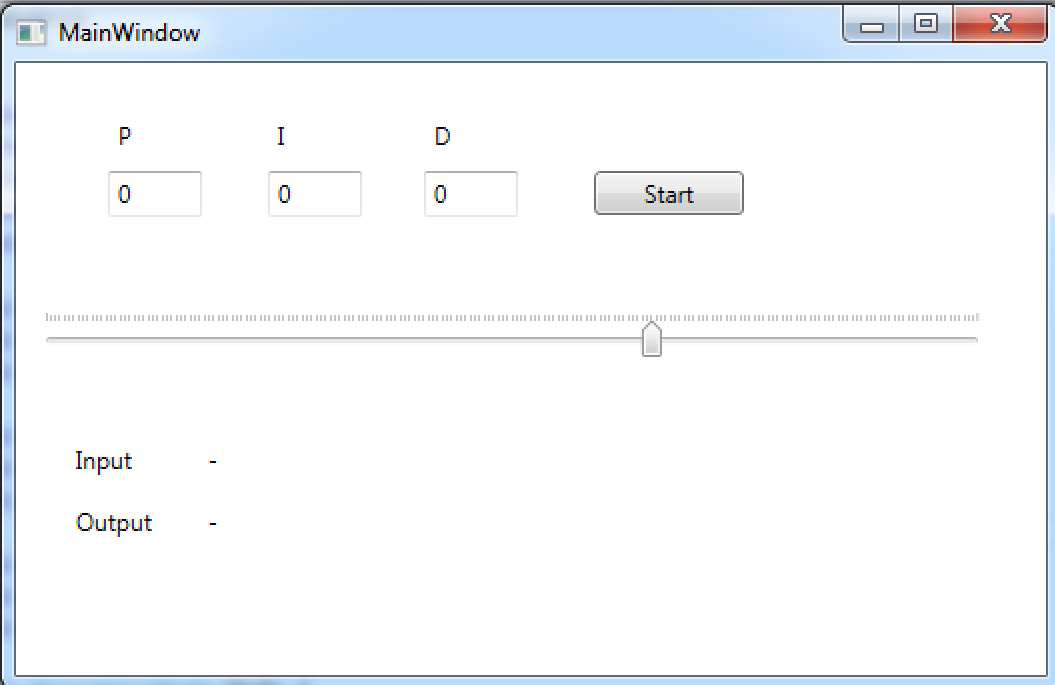
After some trail and error we managed to get the PID-controller to react to a slider in a test application.![]()
Star Wars training droid
Flying training droid that interacts with its opponent.