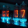
An analogue nixie tube bedside clock
To make the experience fit your profile, pick a username and tell us what interests you.
We found and based on your interests.
Once I had finished the HV supply, I couldn’t just settle for a static number. Before I called it a night I had to make the numbers change.
Given that I have a tray of K155ID1 driver ICs switching the HV is pretty simple. The K155ID1 (SN74141) is a BCD to Decimal decoder and display driver designed for nixie tubes. The HV is supplied to the nixie anode via a 7.5kΩ current limiting resistor and each of the ten numeral shaped cathodes are connected to the ‘outputs’ of the K155ID1.
The K155ID1 is driven by a MC14510, a 4000 series pre-settable up/down BCD counter. The clock is provided by a small clock pulse generator my Dad built 20 years or so ago.
The reader must excuse the untidy breadboard prototype, in my defense it was late. The isolated HV supply can be seen in the background and the aforementioned clock generator to the right.
By the time I called it a night, or should that be ‘called it a day’ given that it was 1AM? I digress. By the time I called it a night I had a single nixie that counted from 0 – 9 and started again. A single counting nixie wasn’t enough though; I was already formulating a plan to have a larger counter. This four digit counter would prepare and test the prototype display driver that would be used when I finally build the prototype clock circuitry.
With parts sorted the next step was to develop a testbed, just a simple High Voltage supply I told myself. Like that ever works, once I started I had to keep going and before I knew it it was 1AM.
Now before we move forward I must remind the reader that High Voltage is dangerous and deserves your upmost respect and undivided attention. High Voltage power supplies for nixie operations often contain DC voltages in excess of 150V and AC voltages at mains potential. The reader must be confidant in working with these potentials before undertaking a project like this. It should be noted that some countries, such as New Zealand, consider this to be prescribed electrical work and thus it must be done by an appropriately licenced person.
Right, with the appropriate safety notices posted I started work on my HV supply. Given the IN-12B nixie tubes require an upkeep voltage of 200V, and the New Zealand mains supply is 230V 50Hz AC I had an ideal supply at my fingertips, all the I need to do was rectify it, right? While technically correct the last thing I wanted to do was have my HV supply at mains potential, even if it was just for testing purposes. My solution was to back to back two identical power transformers, providing full isolation between my supply and mains. These transformers were originally salvaged from standalone emergency lighting units whose batteries’ had outlived their usefulness. A Greinacher voltage doubler on the output of the second transformer proves rectification and the final, stable output voltage.
With a stable HV supply I was able to light up my nixies for the first time. In a word: Gorgeous. As those readers that have worked (played?) with nixie tubes in the past will know, there is something mesmerizing in that orange glow. But static numbers wasn’t enough, and having come this far I had to continue, I had to make the numbers change.
Upon deciding to undertake this project my first step was to take stock of what parts I have available and what I need to acquire.
I didn’t have
any nixie tubes, so they had to be ordered. I settled on six IN12B numeric
tubes, six IN1 numeric tubes and 20 INS1 indicators. All the nixie’s were new
old stock components manufactured in the USSR and were ordered off of an ebay
seller that I have purchased from in the past “alexer1” and came from the Ukraine.
I already had about 20 or so K155ID1 driver ICs, the Soviet equivalent of the SN7441,
which I had acquired as part of a bulk lot of surplus New Zealand Defense Force
electronic components. Incidentally, why did the NZDF have Soviet spare parts? A
quick dig through my box of logic IC’s suggests that most if not all of the
required IC’s were present. Passive components were not an issue either with a
large range in stock. Once the nixie’s arrived the first step would be to
establish a high voltage test bed.
Create an account to leave a comment. Already have an account? Log In.
Another way to get a HV supply is to buy a SMPS converter module for a few bucks from eBay that generates it from low voltage. Also makes your project mains independent. You can also build you own boost converter if you feel buying isn't sporting.
Become a member to follow this project and never miss any updates
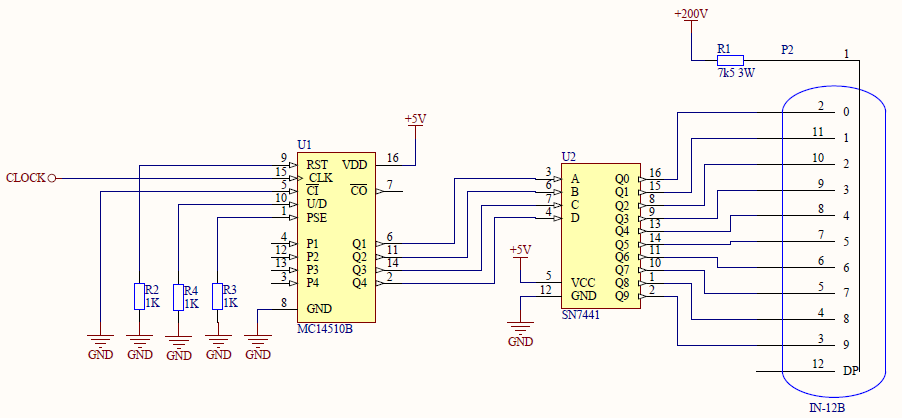
I spent a long time trying to decide if I could wire together a simple couter for my Nixie Jewelry project. In the end I decided it was easier to just use a small micro, but it is good to see a counter being used.