I made a sketch of snapVCC in 2014.
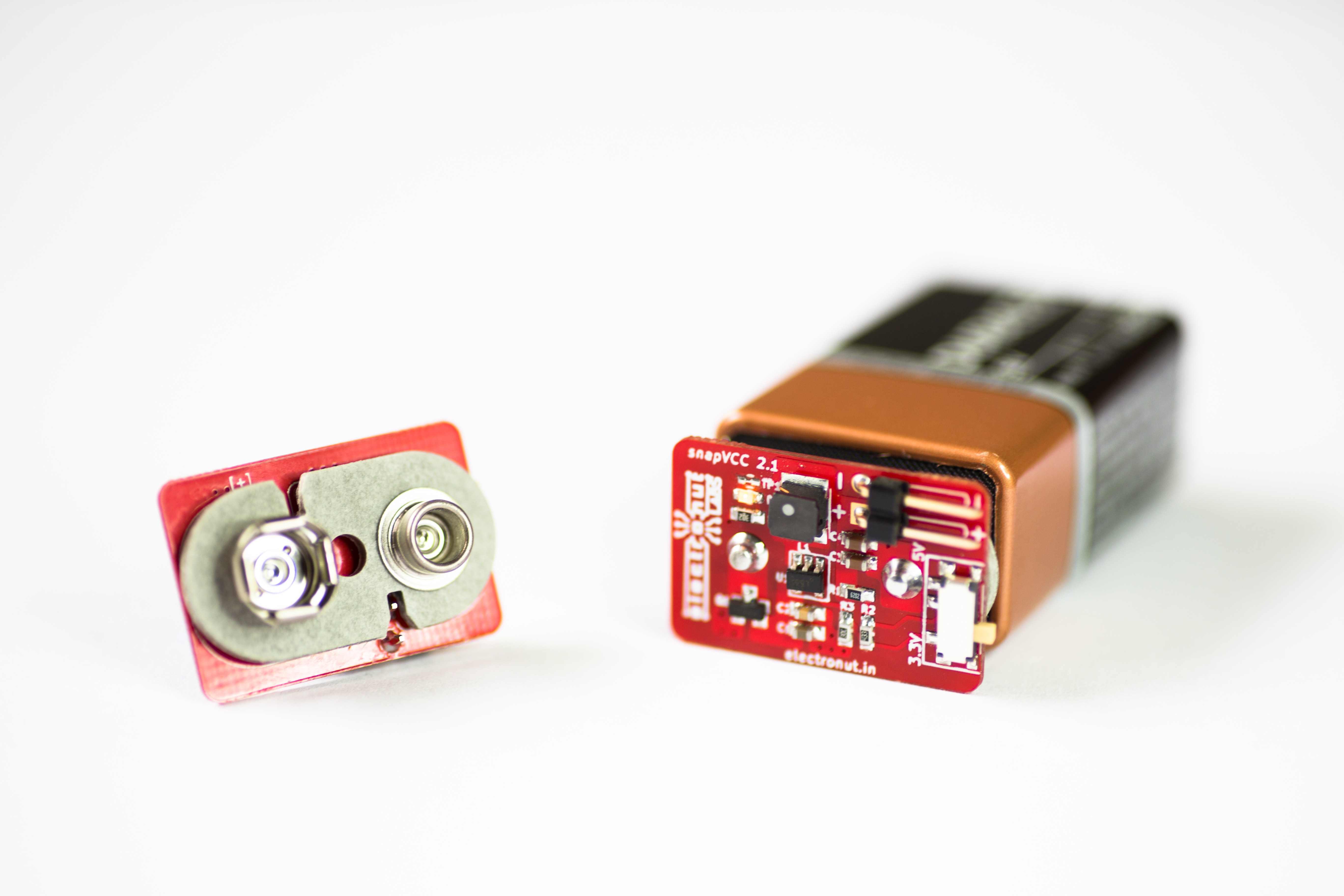
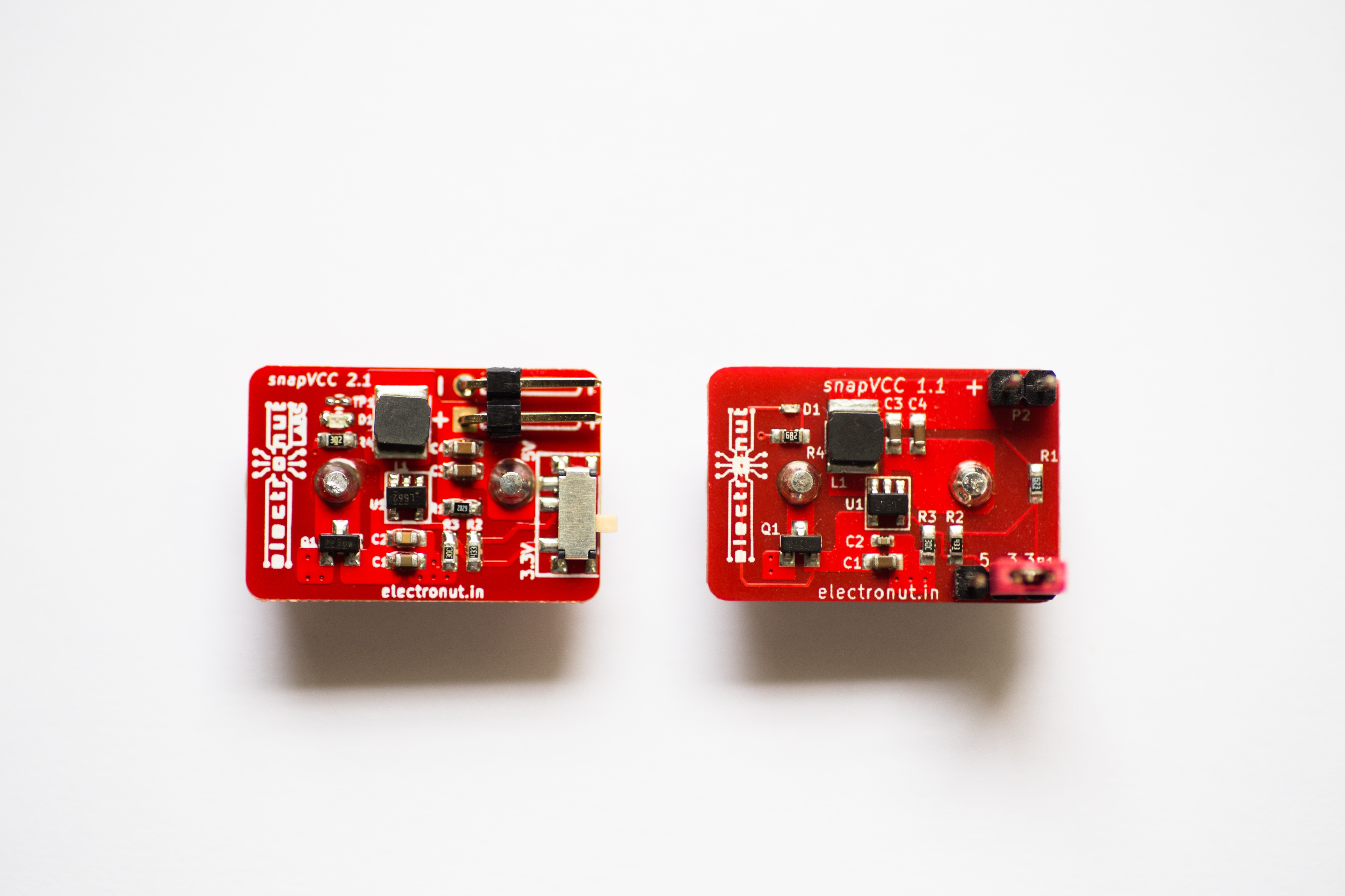
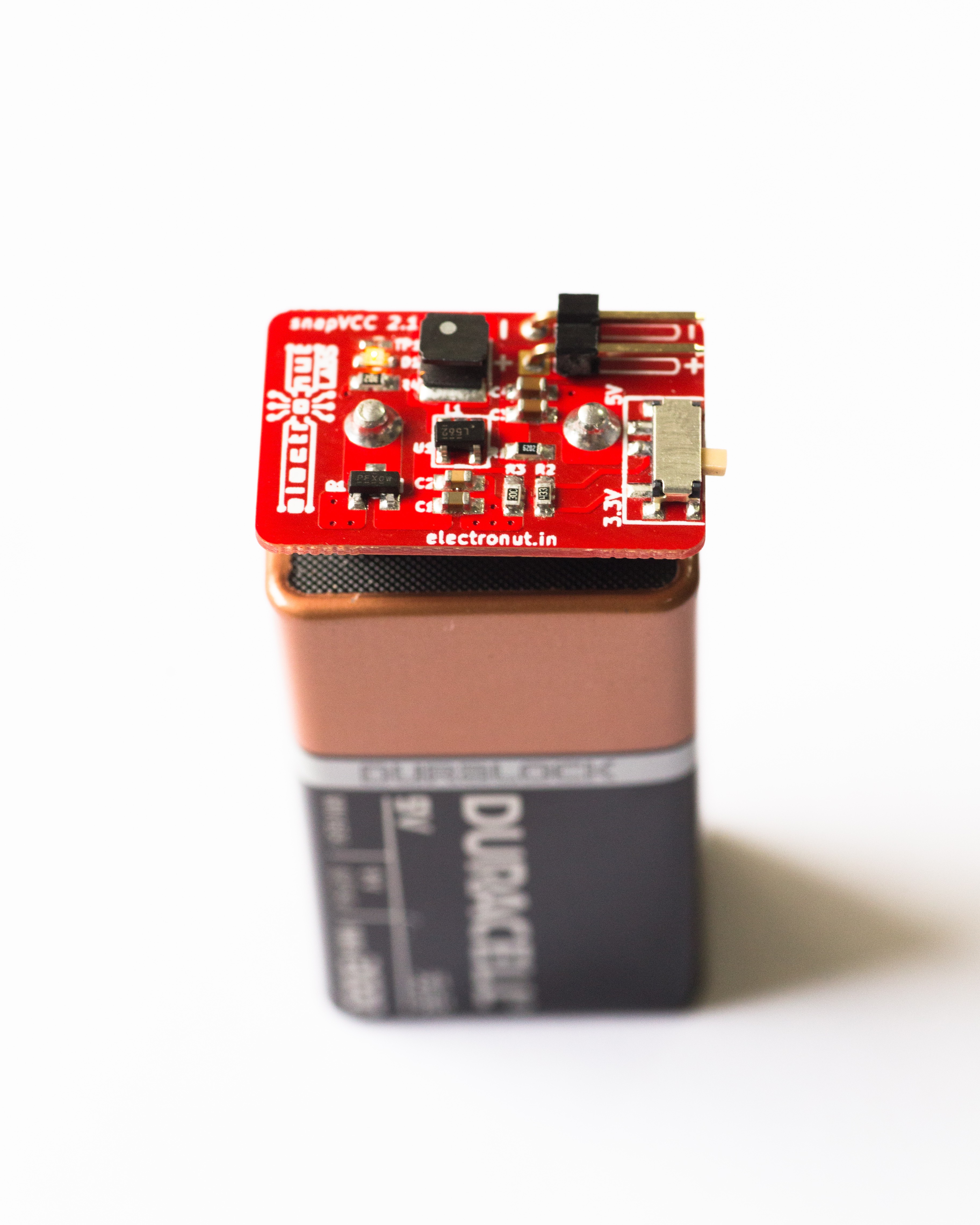
Final design uses a buck converter:

Second revision used a buck/boost converter:

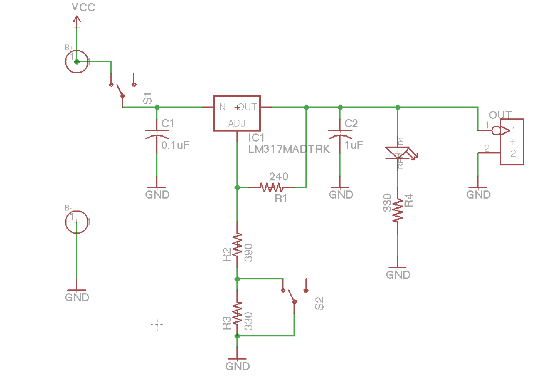
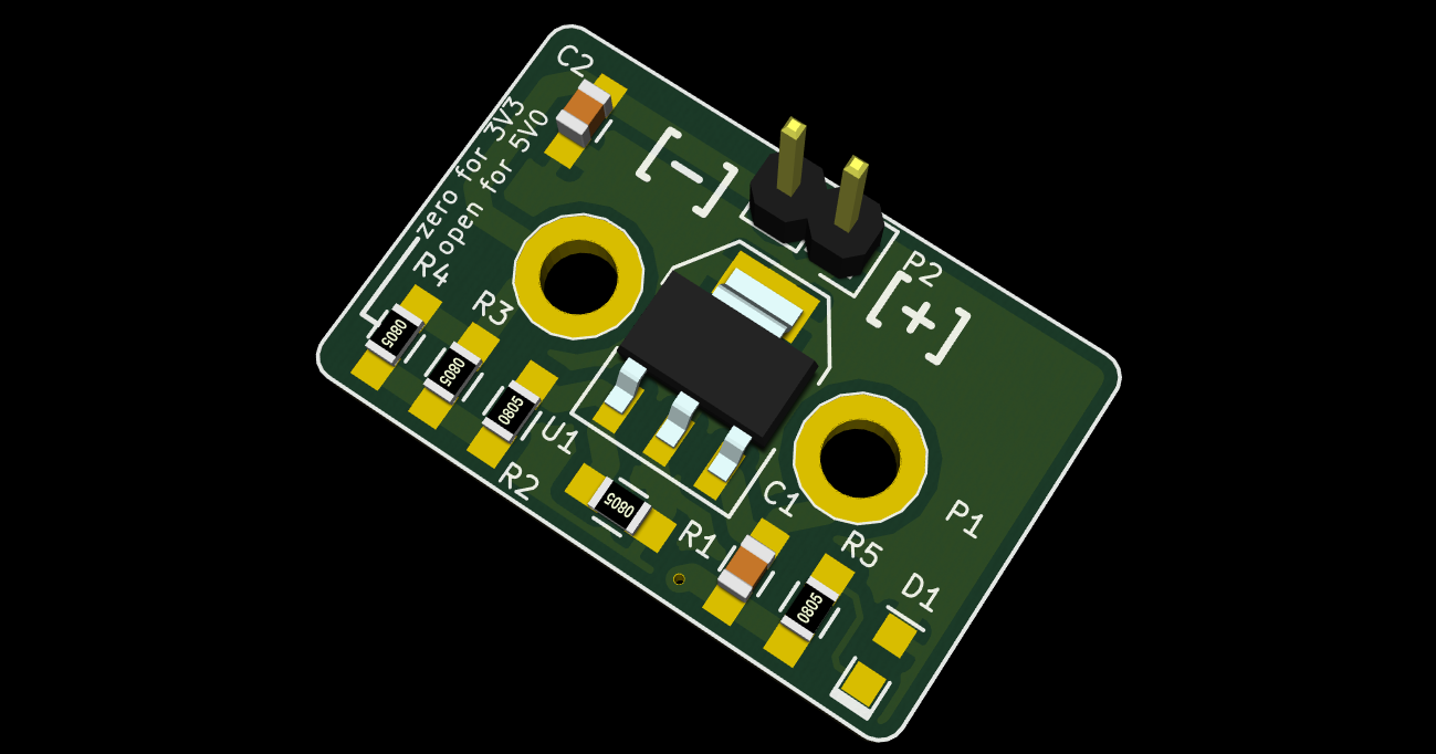
Here is the first prototype, which used a linear regulator.
A snap-on regulated 3.3 V/5 V power supply for a 9V battery.
To make the experience fit your profile, pick a username and tell us what interests you.
We found and based on your interests.
I made a sketch of snapVCC in 2014.
Final design uses a buck converter:

Second revision used a buck/boost converter:

Here is the first prototype, which used a linear regulator.

A few tweaks, and the next version will be out soon...
The first batch of 500 snapVCCs are all sold out, and I am happy to announce a collaboration with Crowd Supply through which we have just released another batch of 500. Available for purchase below:
https://www.crowdsupply.com/electronut-labs/snapvcc
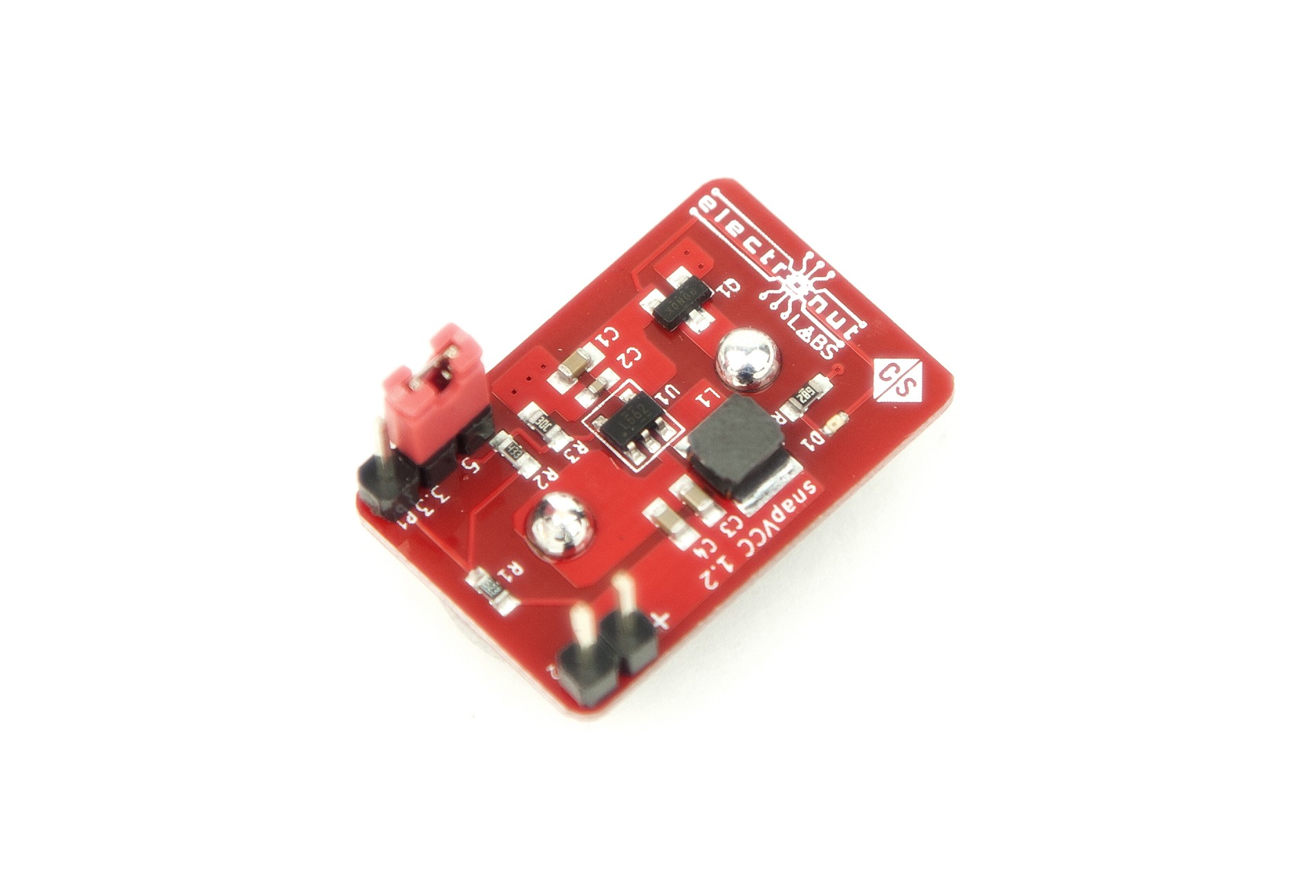
snapVCCs have all shipped out to the backers. There's still extra stock at the Crowd Supply site. I guess I can now consider this project to be sucessfully concluded. :-)
I was at Seeed Studio, Shenzhen for the production of snapVCC. You can read about my trip here:
http://electronut.in/all-roads-shenzhen/

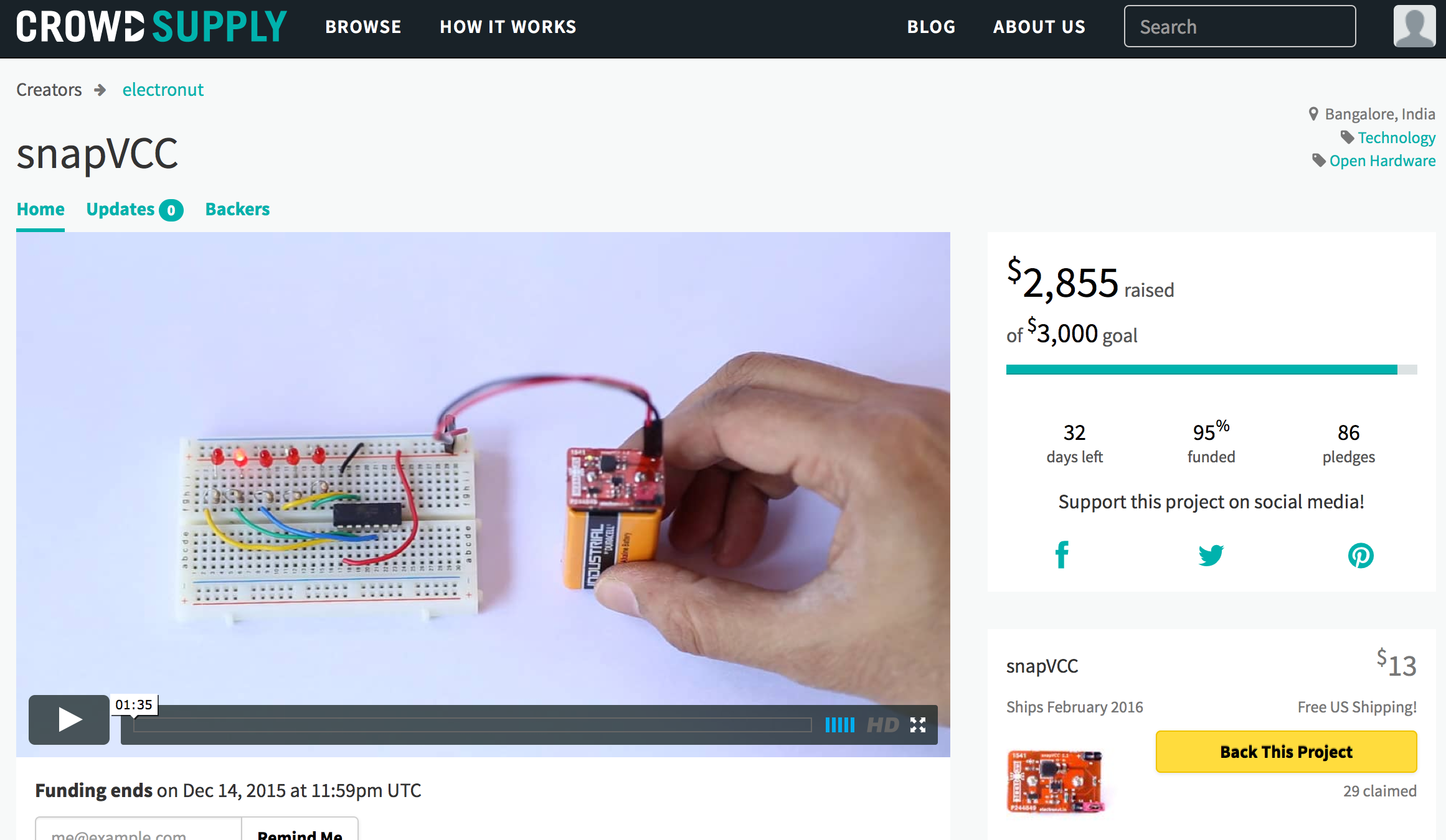
snapVCC crowd funding is done. 157% funded. All set for production now...

300 pieces of snapVCC sold - 13 days to go...
snapVCC is now funded! 105%.
Help, I don't have any nails left! ;-)
Create an account to leave a comment. Already have an account? Log In.
The project seems to be using the TPS560200 step down converter which is specified to output up to 500mA. On the other hand 500mA at 5V means 2,5Watts, thats roughly 300mA at 9V. Your 9V battery might last an hour or less...
Can you share the part number for the inductor used with the TPS56200 ? :)
Taiyo Yuden NRG4026T100M. The whole project is open source - the github link is on top of this page.
Answer to Pete's comment (I don't know, why there is no "Reply" button): Specifying high ESR caps is nonsense! The ESR is a SERIES resistance, high ESR will reduce efficiency.
But I miss a switch - there are really tiny switches - and if this has too little current capacity you can even use the reverse polarity protection FET: Give it a very high gate pull up resistor (>1MegOhm) and switch its gate.
Or you can use the enable pin of the regulator. If you want with two pushbuttons and a resistor (10k to 100k) from the output voltage: 'On' button pulls it to battery voltage for a moment, the resistor works as self holding circuit. The 'Off' button pulls it to GND for a moment, output voltage gets to zero and voltage is off.
If I cut the trace to the LED, how long would a typical 9V battery be able to produce a stable 5V output? Or if it's easier to calculate, what's the quiescent current? I'm wondering if this is usable for remote low power projects where the battery can last a couple months.
Sorry, I am not sure what the no-load current is for the TSP560200 reference circuit. Other than the LED, the only extra component I have is the P-MOSFET. I think the choice of 9V battery also matters. You might have looked into this already, but here are some discharge curves:
http://www.powerstream.com/9V-Alkaline-tests.htm
The TI website says typical Iq for the TPS560200 is 60µA. The vsense resistor chain is either 125kΩ or 82kΩ, equating to 40µA or 60µA. I don't know what the ESR is for all the filter caps, but their datasheets should say. Gate to source leakage on the MOSFET is insignificant at 100nA. I'd ballpark everything at around 0.15mA total, before any sort of load, meaning it would drain a 400mAh 9V battery in about three months. And that's with the trace for the LED cut. If the LED draws 10mA, that's down to two days.
Speaking of the LED, I'm curious why you put it on the supply side. As an indicator, that makes it pretty useless. It will tell you when the battery is dead, but not when the buck converter isn't working due to over-current/temp shutdown or some other fault. For example, if you put a 1A load on it so OCP kicks in, does the LED stay on?
I like the concept and the form factor is brilliant, but I'd recommend you leave the LED out completely, spec only very high ESR caps, and maybe double or some other 'tuple the kOhms on all the vsense resistors if you can. With 9V batteries, it's all about minimizing quiescent current to increase their usable life. At 75µA or less, a battery could last several months running a similarly power-sipping µC app.
Maybe spin a low-q version for your next iteration?
Thanks for the feedback. Will look into these suggestions for the next iteration.
was just thinking something like this would have been super handy the other day. good job!
Thanks! Hoping to start the crowd funding campaign in about 10 days. Here's the link:
https://www.crowdsupply.com/electronut/snapvcc
Hi there,
I'm not sure exactly what size the PCB is but it might be eligible for entry in #The Square Inch Project.
Unfortunately it misses the mark just about - 26 mm x 16mm. :-(
Oh well :( If you can shave off the 0.6mm by November 24, though, you could still enter.
No, it's the final prototype. Maybe after it's crowd funded...
Does it really have to have no edge longer than 25,4mm or does the area have to be less than 1 sq.in.?
I am not sure. In any case, we're past the first deadline...
Nice project, what's the purpose of Q1 in the new circuit?
Thanks! The P-Mosfet is for reverse polarity protection, since it's easy to place the board on the battery with the +/- switched. I learned this trick from this video:
I would consider a Schottky diode (in series) as you don't have a high current application. Should be cheaper than a P-Mosfet.
(hackaday.io doesn't seem to allow more than 3 levels of replies.)
The P-Mosfet apparently has less resistance compared to the diode. The costs is only about USD 0.1 for the mosfet.
Nice and no voltage drop like a diode. Will definately be using that one in future.
Hard to argue with $0.1. :)
Anyway, the Schottky has a "fixed" forward voltage drop (Vf) instead of a given on resistance (Rdson). So you can easily calculate the heat dissipation and compare it to the P channel MosFET if you know the current. P = U I for Schottky and P = R I^2 for the MosFET.
Thanks. I was thinking of a diode till I saw this video.
That was some quick-turnaround from the linear-regulator to switching and now a product! Nicely done!
Thanks very much. Still learning the intricacies of the hardware design cycle. In retrospect, I shouldn't have made the linear one at all...
much easier starting-point and proof of concept... and still usable, for sure.
very clever project. I always thought that it would be cool to make a FM transmitter Bug in this form factor.
I like this idea a lot. Why not do a buck converter version of it? There are some very cheap options out there and your efficiency will be a lot higher. Polarity protection is a good idea too, especially with two exposed contacts on the pc
I've now implemented both your suggestions! :-)
Just found the ideal battery snap clip for this project.
http://www.digikey.com/product-search/en?x=0&y=0&lang=en&site=us&keywords=36-968-ND
It's the same as I am using, as shown in the photo. 967 has shorter leads.
@Mahesh Venkitachalam I made my version of this, battery sized (26x17 mm). Plan to use it as a demo circuit while doing Kicad 101. Here's the Repo [https://github.com/wyolum/9Vsnap] PDF's are in the gerber folder if you don't use KiCad. SMD's are 0805, but with large solder pads to allow hand soldering. Hope it works.
Become a member to follow this project and never miss any updates
By using our website and services, you expressly agree to the placement of our performance, functionality, and advertising cookies. Learn More
 Michael Welling
 Michael Frank Taylor

 rahmanshaber
for a dumb person like me, what is the max current that this thing outputs at 3.3v? at 5v? can't deduce this from the schematics and unable to find that info. it's kinda important imho.