Lucy Fauth
-
Going realtime
03/09/2018 at 20:25 • 0 commentsThe nice thing about the original DigiPan hard- and software is that the image is displayed in realtime as it is exposed. This saves a lot of time, as you can see right at the beginning if an acquisition is over- or underexposed. With the current software setup, however, realtime processing isn't possible: Data needs to be captured first, and then the software decoder can be used for decoding.
I didn't like the sigrok decoder anyway, it was just a quick workaround to be able to somehow capture UART with 13bit. The proper way to do this is in hardware: Either with an actual CPU that supports 13bit framing, or, for more flexibility, a fpga. I had an iCE40 board laying around and the toolchain set up anyway, so I gave it a go. Using an existing UART-echo demo, it was a matter of few hours to modify the code for my application. As I would require an UART speed of 8Mbaud to transmit 13bit data with 4Mbaud as 2x 8 bit frames, I had to configure the internal PLL to get faster clocking. Also, setting the FTDI to a baudrate >2Mbaud isn't supported by the Linux driver, so you have to do this using some usb magic.
Both the verilog code and the python scripts for capturing and displaying are available here: https://github.com/NiklasFauth/iCE40-digipan-hardwaredecoder
Here is a video of the acquisition:
After playing around with pygame and stty for buffering data while received, I managed to get the same effect as using the original Windows 2000 software: The image is being displayed as the DigiPan is slided along the image:
-
First Images
02/26/2018 at 10:24 • 0 commentsWhile for the test pattern only the 5V rail is required, for actual xray acquisition the DigiPan also needs +/- 15V. So the first step was to build a suitable power supply.
![]()
![]()
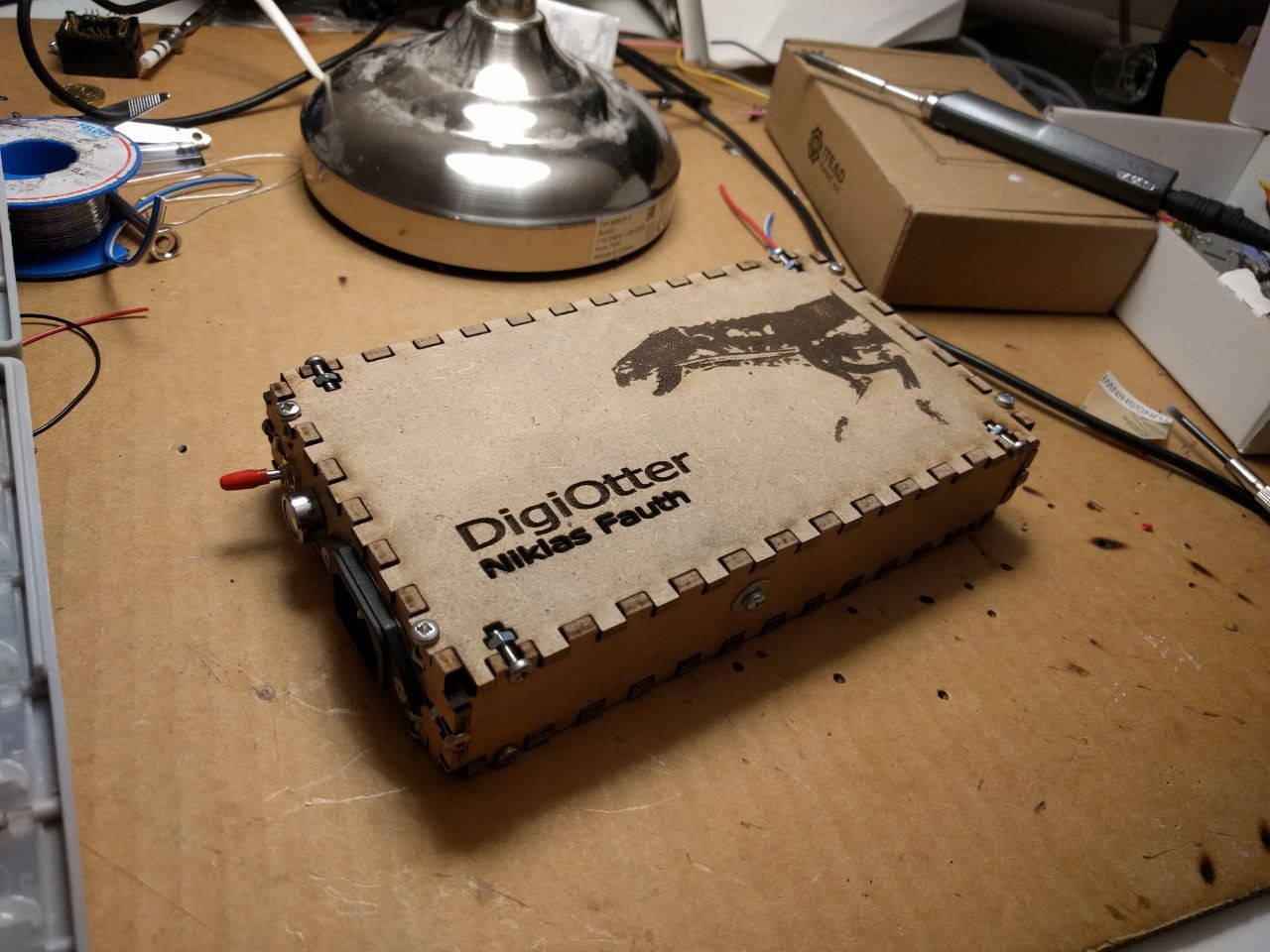
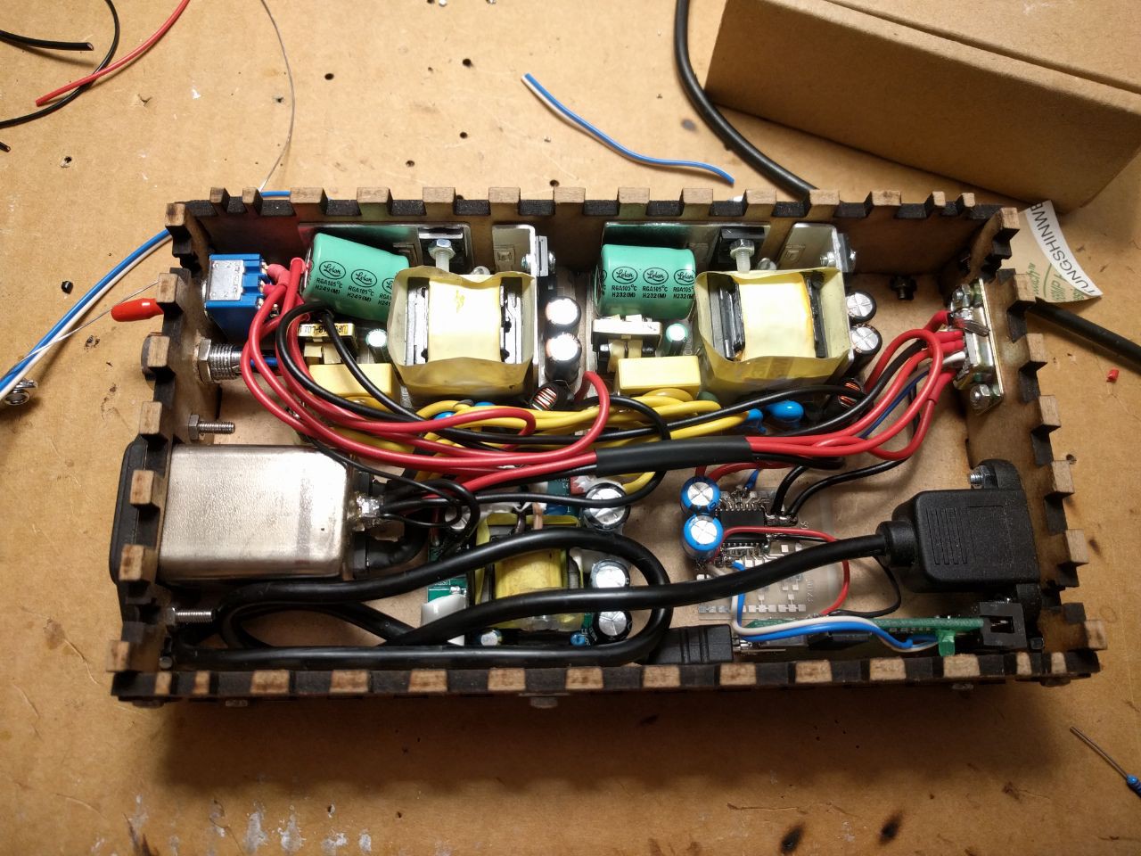
This laser-cutted box contains all what is necessary to operate the DigiPan:- 2x 15V 1A switching mode power supplies
- 1x 5V 3A switching mode power supply
- 1x Saleae Logic 8 clone from AliExpress for 3$
- 1x ISO1176 RS485 isolator to isolate the DigiPan ground from the USB & logic ground
The output of the ISO1176 is connected to one of the logic analyzer inputs. Also the 5V DigiPan power is connected to one input. This is not necessary however it allows to trigger sampling on rising edge of this power rail and thus to the test image sent out at power up, which makes testing way easier.
To slide the DigiPan during exposure we used a linear guide with a built in brushed motor. Speed control by controlling the motors voltage was sufficient at this point. Here is a video of the setup used to capture the first images:
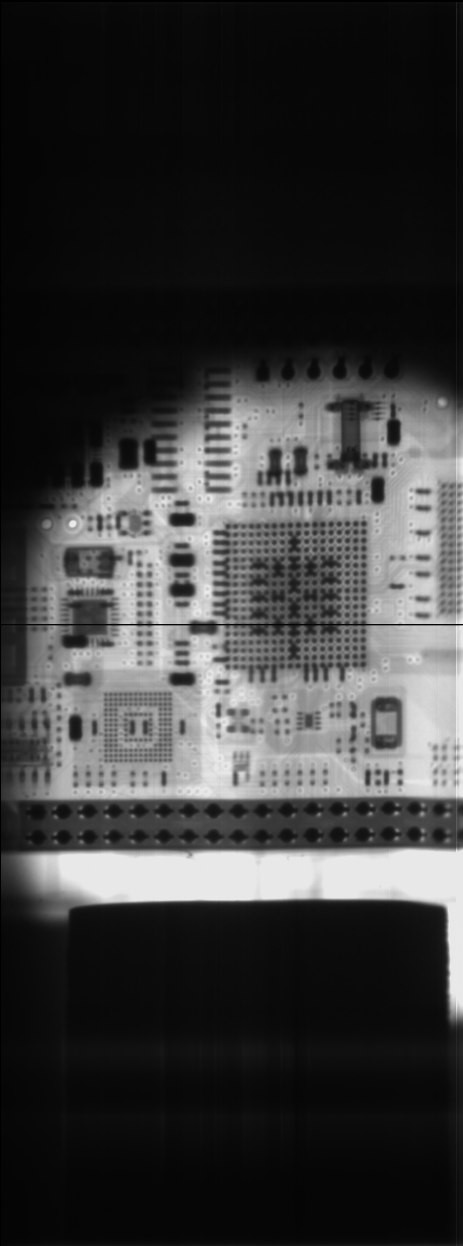
https://twitter.com/FauthNiklas/status/964989555601559553The xray device used for this is a modern handheld fluoroscope used for sports medicine. Output power is 40W at 20-80keV with a very narrow, well focused beam. You can recognize the spot size in the taken images:
![]()
The picture height represents the full sensor resolution of 1244 pixel. This is the xray of a BeagleBone Green. Two thinks you might notice:
The black horizontal line in the middle:
The DigiPan operates standalone, there is no way to start an exposure electrically. Also movement of the panel is a requirement of acquisition, but doesn't start one. The way this sensor triggers is that few pixels in the middle of the CCD are covered from the scintillator. If light level around these pixels rises, the sensor is exposed to xrays and image acquisition is triggered.
The round spot:
As said before, the xray beam is very narrow. It is focused in a way no radiation sidepasses the original detector with 50mm diameter. This, combined with some lag caused by the detection of xray to trigger the acquisition, causes this weird, round shape with one side slightly cut of.
Taking digital xray shots for cheap (< 300$)
Reverse engineering a Trophy DigiPan digital xray image sensor for 2D and CT 3D images.