Close
0%
0%

$1/W True MPPT

Build a $1 per Watt parallelizable MPPT controller, without cutting corners.

Similar projects worth following
Maximum Power Point Tracking (MPPT) is a technique whereupon special electronics attempts to extract the optimal amount of energy from a solar panel. This optimal point fluctuates in function of a variety of factors including: temperature, quantity of incoming light, solar panel age, etc.

Current MPPT controllers tend to be expensive. They range from tens of dollars for 3W supplies to hundreds of dollars for 100W and above. Lower costs can be achieved but typically trade-off functionality essential for proper MPPT operation. This makes MPPTs poor candidates for cost sensitive applications.

If the cost could be reduced to a more attractive price point, MPPT controllers could become synonymous with solar panels, opening doors for new renewable applications.

The goal of the project is to provide MPPT functionality at a fraction of the cost of current off-the-shelf solutions. Ideally, the entire MPPT controller would cost $1 and work on 1W panels and above.

The initial design cost close to $10, but had room to significantly cost reduce. The most up to date design, a large improvement on the original, relies on a tricky hack on override the default behavior of an off-the-shelf buck regulator, and subsequent versions have provided additional cost and performance improvements. The current cost for this circuit is $2.41.

A note about this project. While there already exists hacks to do MPPT on the cheap, those hacks typically rely on some intervention from the user to tune the MPPT to the ideal point. The goal here is to create a true MPPT controller which could be used in 3V solar panels as well as 24V solar panels with no manual tuning.

  • Still Alive

    Jonathan Bruneau08/21/2018 at 05:46 0 comments

    Despite it being over a year since my last project post, I'm still alive.

    Quite a few things have changed since my last post. I’ve had a major job change, a house change, and a +1 to the family. Needless to say, I haven't’ been able to do much on this project.

    This doesn’t mean that I’ve stopped working on it: au contraire! My pace might have slowed significantly, but I haven’t stalled.

    I’ve completely revamped the power supply. Primarily in function of the larger 9W solar panels you can now find on Adafruit, Sparkfun, and other sites. I’ve also changed ECAD tools, opting for CircuitStudio. I’ve always liked the schematic+layout integration Altium tools provide, and now I can have my cake without breaking the bank.

    In designing this latest supply, I’ve made a few notable changes which made the board significantly larger and more expensive.

    These include:

    • 5A input and output support for larger solar panels.
    • 24V input and output support for larger solar panels and battery banks.
    • FTDI header output for UART debugging.
    • Firmware controllable output voltage and output current limits.
    • Fun LEDs and much more!

    This seems counter to all my previous logs, and you’d be right in thinking so. The rational here is three fold:

    1. I don’t have nearly as much time to optimize the design.

    2. The basic set of components required to provide MPPT support is a fixed cost that is hard to further optimize (proof, the rest of this project’s logs).

    3. Addressing some of the shortcomings of the previous design requires additional costs, which are best amortized by pushing more power.

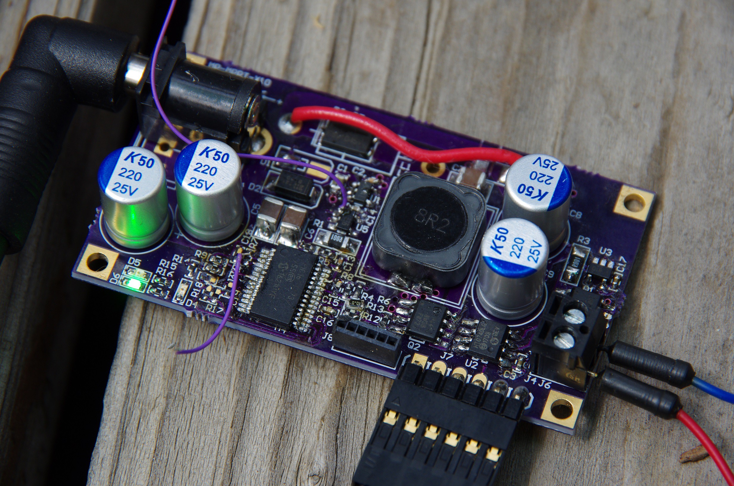
    The design worked out fairly well. Powering this entire endeavor is a PIC16F1773, with 6 comparators, 6 DACs, and 3 OpAmps (no typos). As configured, this SEPIC power supply offers cycle-by-cycle input under-voltage protection (UVLO), intput and output over-current protection (OCP), and output over-voltage protection (OVP).  The PIC is also setup to directly drive the FET with it's two beefy 100mA output drivers.  Not bad for $1.80/PIC.

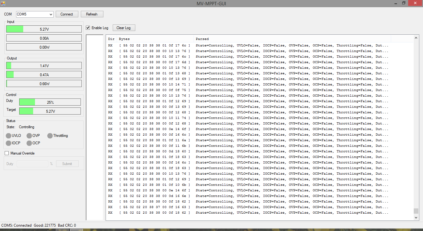
    The design worked well enough that I even bothered making a GUI to help me debug the bringup issues (I connected a UART to the PIC) (note that the input and output current readings (and thus power readings) are completely trash, that needs to be addressed in a future spin of the power supply).


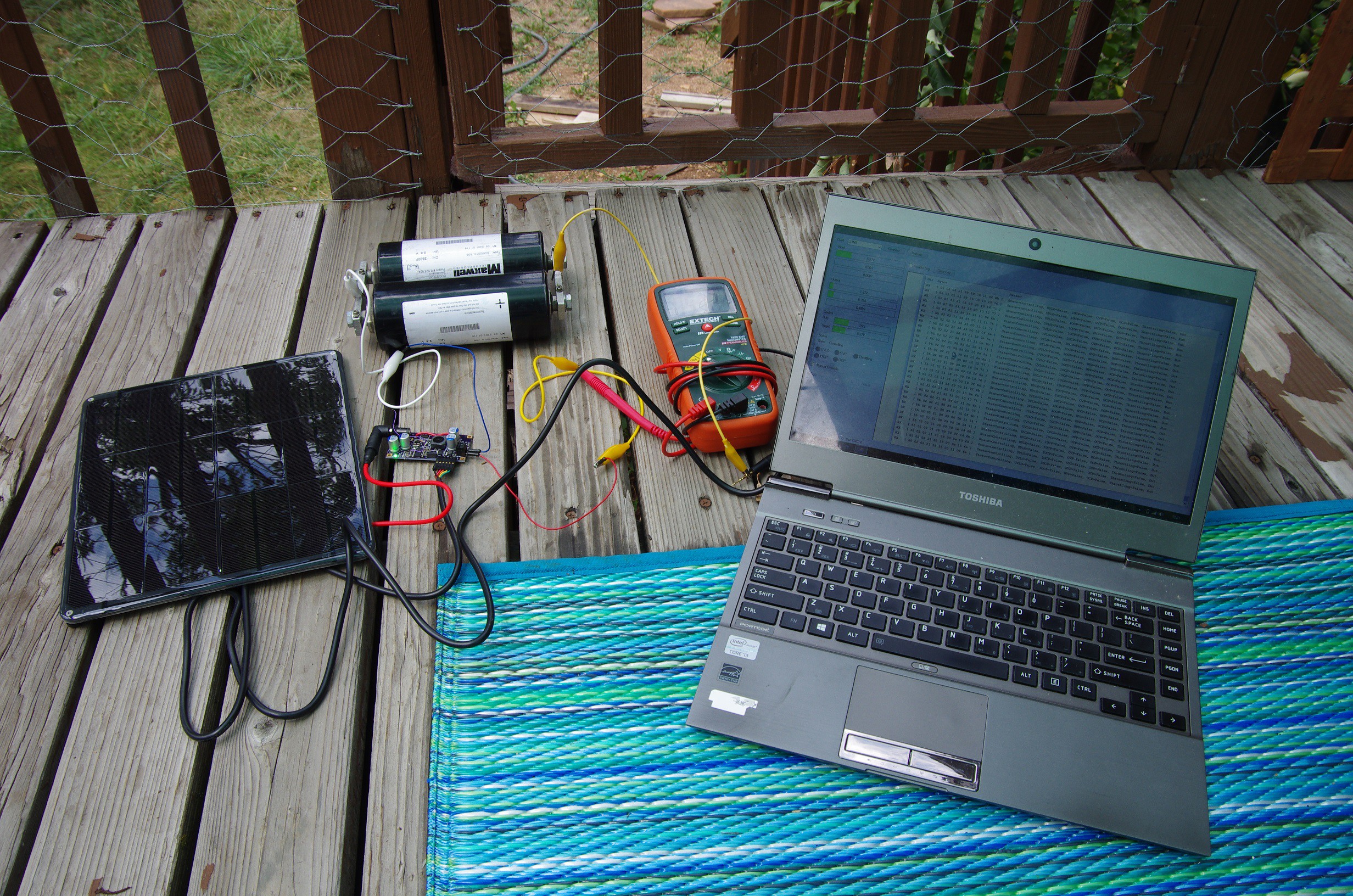
    At it’s peak, I was able to push out over 2A from the 9W/1.5A panel sold by Sparkfun. The output current was so high that I measured over 0.5V of drop in the cable between the supply and the supercap bank alone!

    I also managed over 85% efficiency, which is pretty decent (but not great yet).

    All said in done, my bill-of-materials amounts to $8.17 @ 1000 QTY, not including the 4-layer PCB. For a 9W panel, this comes out to be slightly more than $1/W, which isn’t bad. But for a 3W panel, this is completely overkill.


    The design turned out to be rather expensive in an attempt to remedy three major issues: Precision, Efficiency, Flexibility.


    Precision

    The internal reference of the PIC16F1773 has a +/- 4% tolerance across the entire temperature range.


    While this large tolerance doesn't matter much when measuring small analog signals, when measuring a large 24V through a voltage-divider, it can mean the difference between measuring 23.59V or 25.56V, which is a huge error margin.

    Worst yet, the resistors used on the voltage-divider are all 1%!  In itself, this tolerance will provide a measured voltage range of 23.66V to 24.70V. These two sources of error, combined, make a cheap voltage measurement solution unacceptable.

    So I add a MCP1501 high precision external reference, and upgrade the output voltage sense resistors to 0.1%. This, naturally, adds cost.


    Efficiency

    Previous MPPT designs operate fairly well at light load, but as the output amperage increases, their efficiency drops. The losses come in many forms, but the most obvious paths include.

    • Losses in the forward...

    Read more »

  • OpAmp Be Gone

    Jonathan Bruneau05/10/2017 at 23:42 0 comments

    Wait a second...

    I just finished uploading my latest project log, and it got me thinking. Maybe I can get rid of the OpAmp altogether and still successfully implement over-current protection.

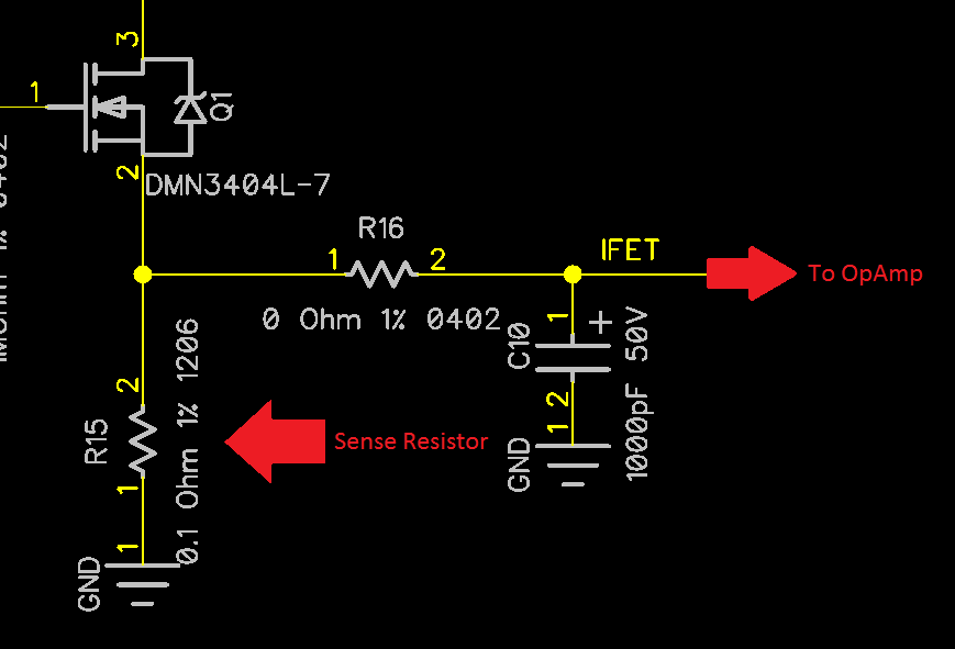
    Here's the thought. The way the latest SEPIC design implements over-current protection is by amplifying a small voltage drop across a sense resistor, right after the MOSFET.

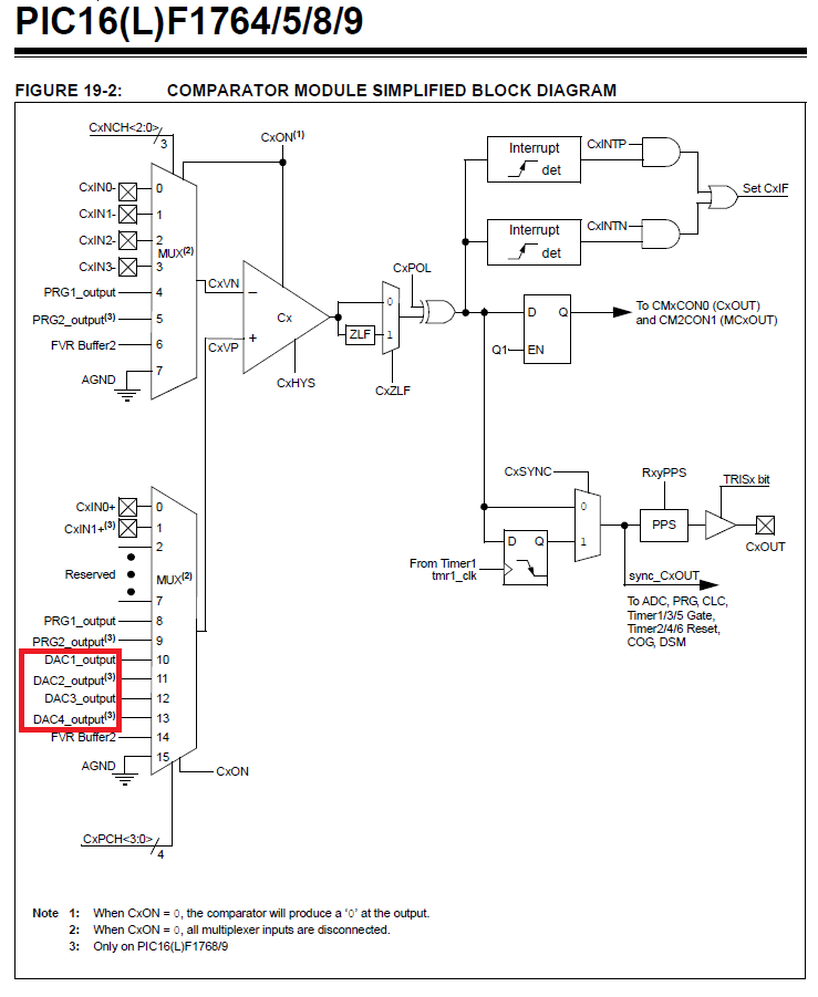
    The truth is, the PIC16F1764 has a DAC that can be wired as one of the inputs to the internal comparators.

    So instead of amplifying the signal using a OpAmp, I can use a DAC to decrease the comparator's input voltage, essentially doing the same thing.

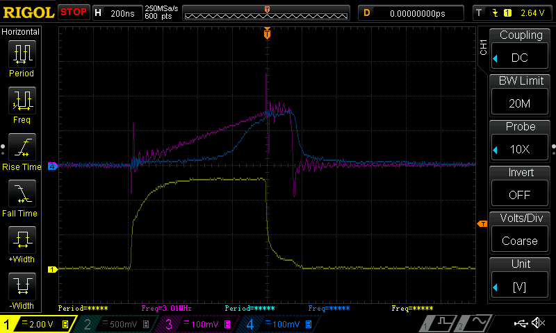
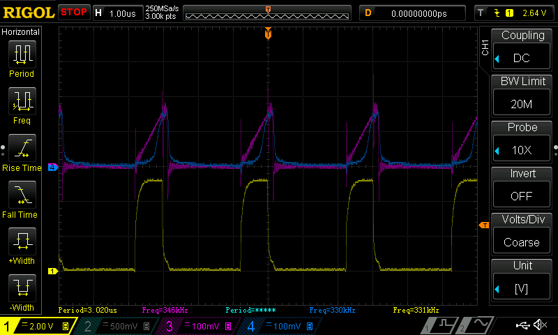
    This is just a firmware change away, so I tried it. It works like a charm! Below is a graph of the net result. The yellow line is the PWM going into the gate of the MOSFET, the magenta is the voltage across the sense resistor, (the blue is the OpAmp voltage, set as unity gain (hack needed to make this work with current PCB)).

    Notice the smooth ramp-up in voltage on the magenta line. That's the voltage increasing across the sense resistor. By changing the output of the DAC connected to the comparator, I can change the over-current set point. Neat, don't you think?

    Ok, so now to find a MCU with a high-speed PWM, two comparators and a DAC that can connect to a comparator inputs. Should be easy to find.

    HA, check this out: brand new chip: PIC16F15323, $0.53 @ 1k! If the PWM lives up to the datasheet, we might have a winner. This MCU doesn't have the 100mA GPIO drivers, but at 50mA I can double down on the number of pins used to drive the MOSFET. This just might work.

    Needless to say, I've ordered some of these PICs. I'll keep you posted with more details.

  • Return of the SEPIC

    Jonathan Bruneau05/10/2017 at 23:11 1 comment

    A long time ago (man, almost 1.5 years ago) I tried my hand at a SEPIC, with mixed results. While the topology indeed works as a MPPT, the two inductors required by the topology made the cost quickly go out of budget (switching at 31kHz). So, I canned the idea.

    But after reflecting on the findings of my latest MPPT hack, I started thinking about the SEPIC once more. This latest hack works quite well, but suffers from a fatal flaw: the maximum output voltage can only go up to 6V. There are a lot of applications out there that require a 12V output, so 6V just wouldn't cut it.

    I needed something that could output 12V, and in the spirit of this project, could output 12V irrespective of the input solar voltage (lower or higher than 12V). This naturally brought me back to buck-boost topologies.

    So I started looking for boost or buck-boost regulators that could be hacked into MPPT controllers. The results were not encouraging. I found that in my price range, the regulators were one of more of the following:

    • Unable to output enough current.
    • Too expensive.
    • Switching too slowly, requiring large inductors.
    • Too inefficient

    And on top of using hacking a regulator, I would still need a MCU to start/stop the regulator for Voc (Open-Circuit voltage) sampling, crucial in finding the MPP.

    This is when I started turning my brain on.

    Hey, if I need to have a MCU anyways, it would be a hell of a lot cheaper to replace a hacked-up regulator with a MOSFET (cheaper by an order of magnitude) and use a SEPIC as long as it was switched fast enough to keep the inductor sizes small (a.k.a. within budget).

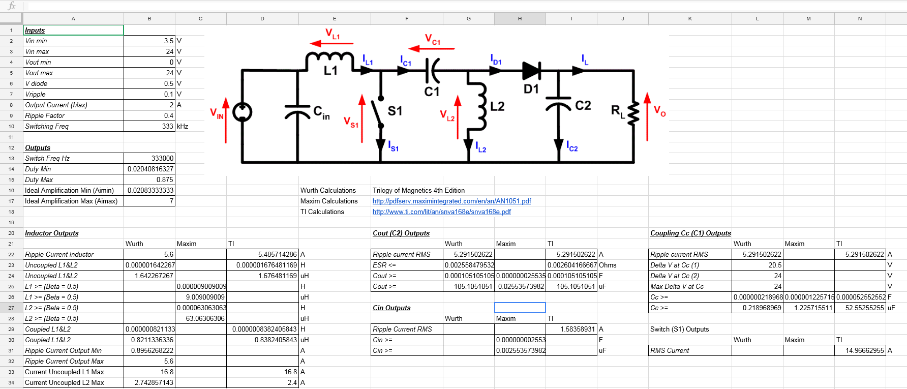
    How fast? Well, pretty fast actually. Anywhere in the 300kHz to 1MHz range. I made a spreadsheet to calculate exactly how fast I needed to go, using equations given from three reputable vendors. You can see it here (or just look at the pretty picture below).

    333kHz seemed to be as slow as I was willing to go, which gave me a 1.6uH inductor size. To my surprise, the amount of output decoupling is enormous, 105uF @ 333kHz! At 500kHz, that value thankfully went down to 70uF.

    The key at this point was finding a MCU that could generate a >= 300kHz PWM signal with sufficient resolution at a price point lower than using an external boost regulator + MCU. I say sufficient resolution because with most (if not all) PWM peripherals, as the period decreases (i.e. increasing frequency), the number that can be used to represent the duty cycle also decreases. The fewer bits available, the coarser the MPPT becomes. If too coarse, the MPPT cannot successfully settle on the actual MPP. I ran into this issue in the past and talked about it in this blog post.

    Turns out finding a sub $0.60 MCU that can switch at such high frequencies while retaining sufficient duty cycle precision is quite hard. I only found a handful:

    • PIC12F1571
    • PIC16F1764 (over budget)
    • ATtiny25
    • XMC1100
    • XCM1301
    • EFM8BB
    • <insert your suggestion here>

    Factor in other variables such as:

    • The design needs to have at least 1 comparator, preferably 2.
    • The design needs an OpAmp for over-current sensing.
    • The design costs can be reduced if the external MOSFET driver can be replaced with MCU GPIO pins.
    • The MCU needs to have a ADC for Voc sampling and tracking.
    • I just want to prototype the damn thing at this point.

    And I ended up using the PIC16F1764. The integrated OpAmp + 2 comparators + 16bit PWM operating at 32MHz + 100mA (not a typo) high current drive MCU pins + the fact that I already have some lying around tipped me over. For a 333kHz oscillation, I would end up with a period value of 96, meaning I would have 96 discrete steps for duty cycle. With a max of 24V input, this would give me a resolution of:

    I found this acceptable enough to bother making a PCB for it. Here it is, in all it's glory.

    I ended up using a slightly larger inductor than calculated in my spreadsheet to give me a margin of error. I used SRF0703-3R3M, a 3.3uH coupled inductor. (The astute observer will also notice that I actually used a PIC16F1768, but that's a complicated...

    Read more »

  • Being Hard with the Soft-Start

    Jonathan Bruneau02/03/2017 at 07:36 0 comments

    As part of my weekly routine, I run a Digikey search in the "Voltage Regulator" and "Voltage Controller" sections in hopes of finding a better, cheaper alternative to the RT8299. I even have the searches saved: try them out if you're interested:

    Why looks for a new regulator? Why hate on the RT8299? Because it tempts me.

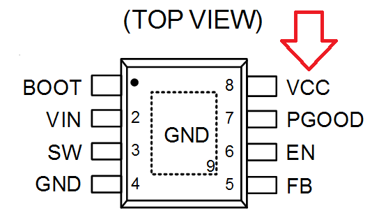
    Here's why. Take a look at the pinout of the RT8299.

    See the VCC pin? Well, dig deeper in the datasheet and you'll find that this pin is actually the output of an LDO.

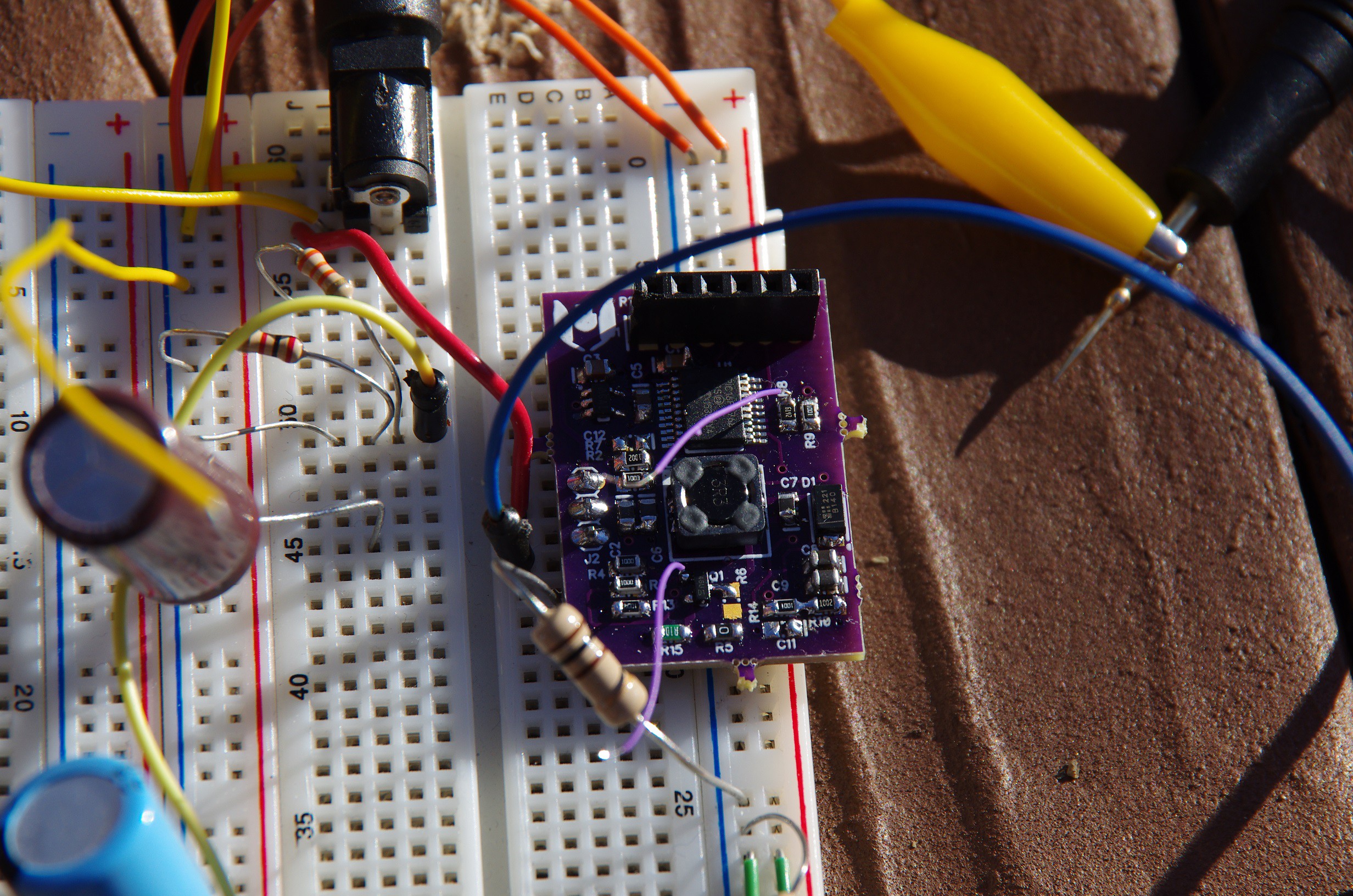
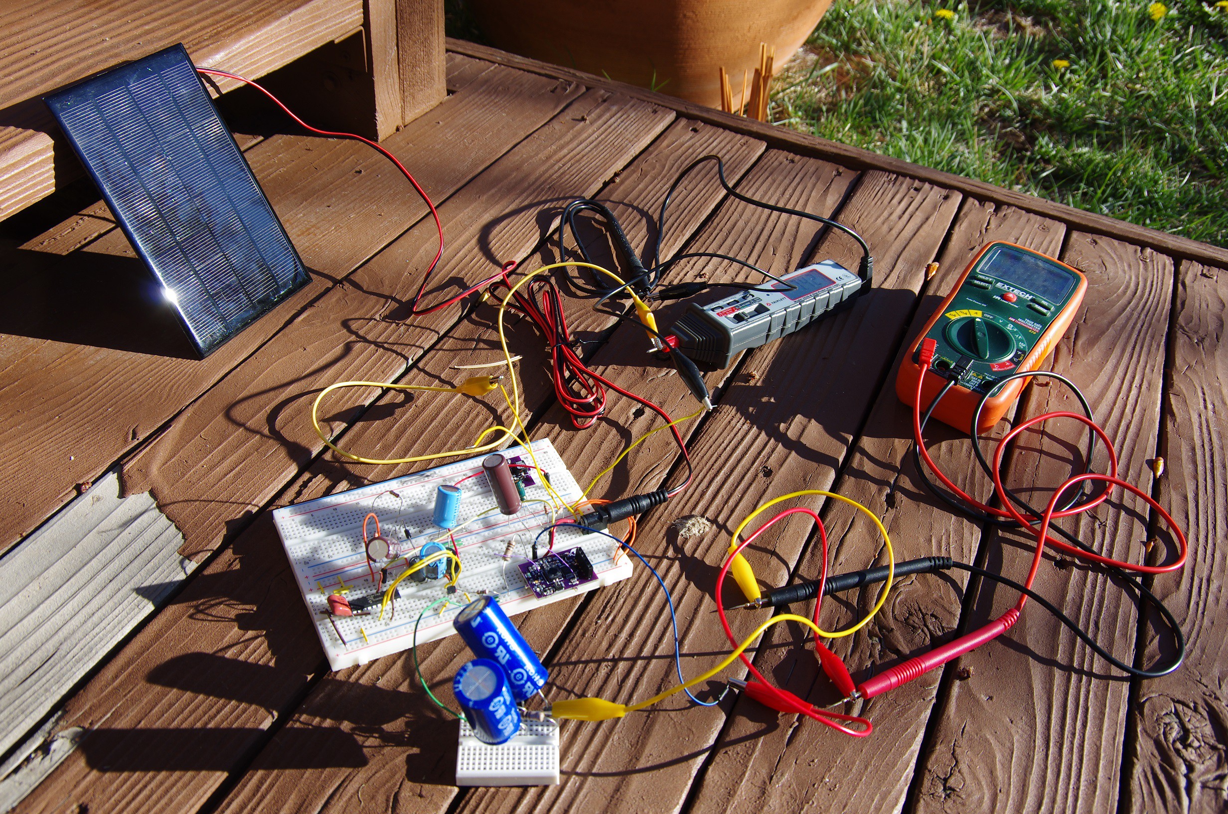
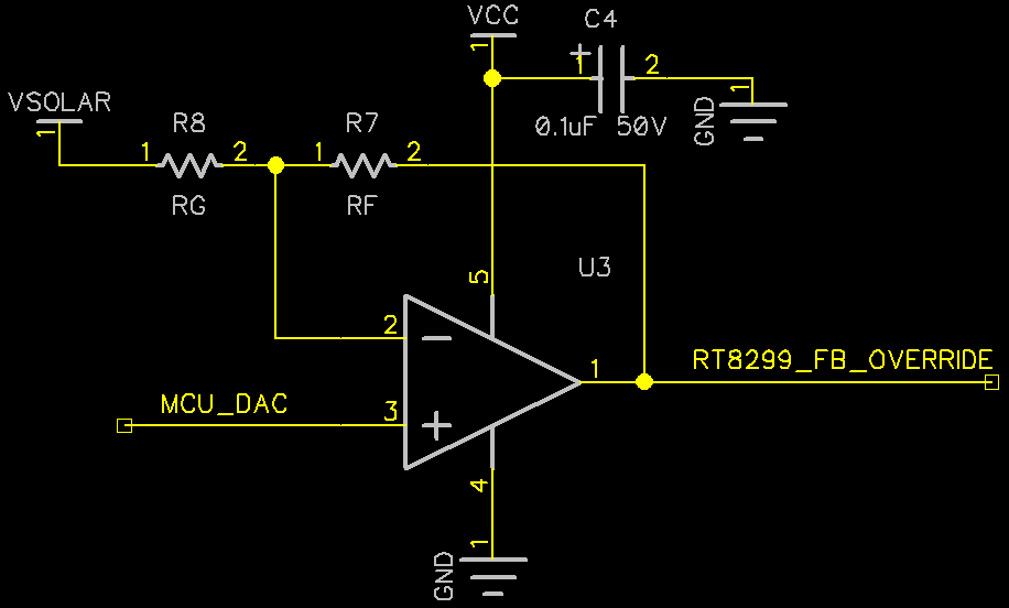
    For the astute (and long term memory) observer, my latest and greatest hack of this RT8299 requires an external LDO regulator to power the PIC MCU used to override the default behavior of the RT8299 (see this post if your memory fails you).

    Given that the RT8299 has a LDO built in, and it's exposed to a pin... well damn, I "should" be able to use it and rid myself of this unholy external LDO! Yoohoo!

    "Should" is the correct answer. The RT8299 fails us in two ways.

    1. The RT8299's internal regulator only powers on when the EN pin is high.
    2. The voltage coming out of the regulator is said to be 5V, but goes all the way to 9V as VIN rises.

    I like how the datasheet discretely fails to mention point 2.

    Having VCC go above 5V is actually a good thing, as this voltage is used to drive the FETs. Higher drive voltages result in higher efficiencies. That being said, it's terrible for powering a MCU. There are a handful of higher voltage MCUs (mostly from Microchip), but the cost prohibits their usefulness (with one notable exception, sort of).

    To make things worst, with the enable pin always high, there's no way for me to properly stop the RT8299. Stopping the regulator is crucial to sample the open-circuit voltage (Voc) and to prevent an over-voltage condition on the output.

    This is where those weekly Digikey searches come in.

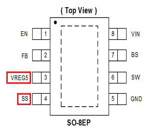
    As part of my weekly ritual, I peruse the datasheet of new parts that crop up to see if anything juicy strikes my fancy. About a month ago I landed on this guy: the AP65452.

    The specs aren't perfect, but the pinout certainly is: a stable 5V VCC, and a soft-start pin, exposed!

    For the uninitiated, the soft-start pin usually connects to a capacitor and is charged with an internal constant current source. This voltage is then used to limit the rise time of the output of the regulator. All in all, it eliminate large inrushes of current, and that's a good thing.

    It's especially a good thing since the 5V regulated output is, like its RT8299 cousin, only enabled when the EN pin is high. This means I cannot use the EN pin to start/stop the regulator. But thanks to the soft-start pin, I have an alternative way to keep the AP65452 disabled. With the help of a single N-channel MOSFET, I can keep the soft-start voltage close to GND (i.e. prevent the capacitor from charging) to prevent the AP65452 from turning on.

    Now we're cooking with oil! The regulator can power up, enable the internal LDO, and stay off until the MCU wakes up and is ready to go.

    This had enough legs to run, so I made a board and tried it out.

    The same OpAmp feedback pin override technique was used to adjust the maximum power point, and it worked as expected. Horray!

    Is the AP65452 the final solution? It depends. It's Vin range is smaller than the RT8299 (4.5V-18V vs 3V-24V) and the maximum output voltage is 6V, hardly enough to charge 12V batteries.

    Do I need to care about 12V output? Maybe this is something you can tell me.

  • Timing Isn't the Answer

    Jonathan Bruneau02/03/2017 at 06:01 9 comments

    It's been far too long since I've posted an update.

    I am still, in fact, working on this project. In my last project log I was trying to find a way to enable/disable the hacked RT8299 buck regulator to give me a open-circuit voltage (Voc) reading, which is then used as the maximum power point target until the next sample is taken.

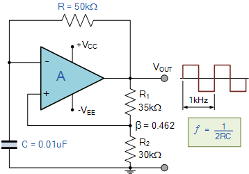
    I've played with a variety of different oscillators, and eventually landed on a single Op-Amp multivibrator. It's an attractive solution thanks to the low parts count: offering a potential for significant cost reductions. The basic circuits looks like this (image courtesy of this site):

    The principle is quite simple. The OpAmp acts as a comparator, comparing the voltage on a capacitor to a reference voltage. The reference is generated right off the OpAmp's output (R1 & R2), and resistor R is used to limit the charge/discharge rate of the capacitor.

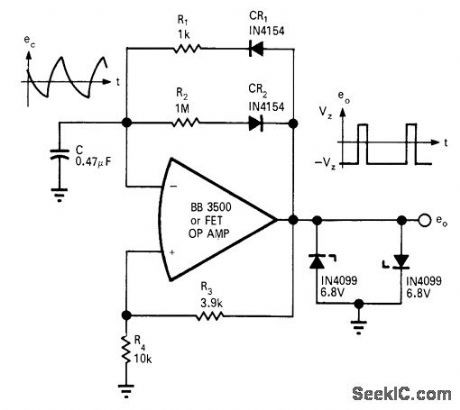
    This basic multivibrator circuit generates 50% duty cycle square waves, but for this MPPT application, I need something closer to 99% duty cycle (sample VOC briefly, turn on RT8299 and track MPPT the rest of the time). This can be easily done by adding a diode in parallel with resistor R to provide a fast discharge path. To control the discharge rate, another resistor is used in series with the diode.

    The modified circuit ends up looking like the image below (found from this site, which contains enough interesting material to keep folks such as myself busy for entirely too long):

    The only difference between this image and the actual circuit I build was that the values of R1 and R2 are flipped, effectively inverting the output duty cycle.

    This circuit works well and integrates nicely with my current MPPT implementation, with a caveat. In order to get long periods (over 10sec), I need a large RC time constant. To keep cost down, I chose the largest R in my arsenal in an attempt to make the C reasonable.

    Bad idea!

    With a sufficiently large R, not enough current enters the input of the OpAmp (they have a required minimum, usually referred to as the "Input Offset Current"). When not enough current enters the OpAmp, the circuit no longer oscillates.

    This left me with the uncomfortable position of having to chose a large C, which is more expensive.

    Right off the bat, this doesn't sound like a deal breaker, until you add up the costs. After adding the cost of the OpAmp multivibrator, the large timing capacitor, the reference voltage used to regulate the output, the output comparator (an OpAmp "can" be used with sub-par results), the feedback override OpAmp (see this post for an explanation) and the Voc sampling circuit (see this post), it ends up being cheaper to use a PIC.

    Somehow the universe decreed PICs to be amazingly cheap.

    All this to say, I'm no better-off than I was prior to this nonsense science.

    This is just part of the news. I'll post another entry with my other experiments.


  • Timing is the Answer

    Jonathan Bruneau08/03/2016 at 04:21 4 comments

    It's a great song by the way.

    As discussed in my previous project log, I was able to remove the ADC and DAC otherwise needed to perform the MPPT algorithm, vastly simplifying, if not outright eliminating the need for a microcontroller. The motivation is simple: save cost.

    But there's a caveat to this plan of mine; I still need a timing circuit to briefly turn the RT8299 buck regulator off to sample the open current solar panel voltage (Voc). This is where things get interesting.

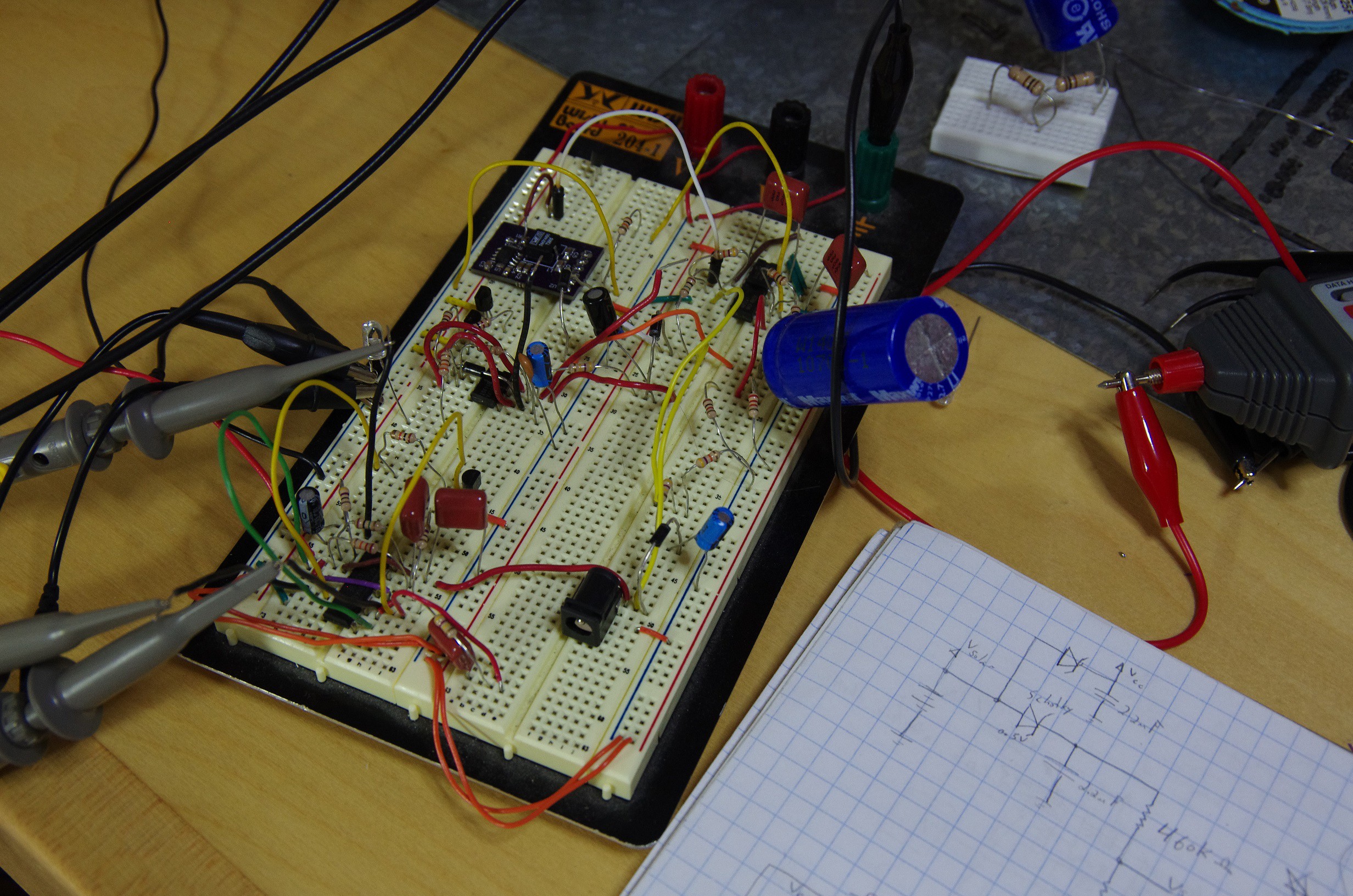
    As shown by my latest breadboard, I've tried a variety of options. I'll discuss the two most interesting below.

    My first inclination was to replace the MCU with the good 'ole trusty 555 timer. These ICs have been around since the dawn of semiconductor (mild exaggeration on my part), and today sells well over a billion units a year (not an exaggeration on my part). If you'd like to read more on it's fascinating history, I'd recommend this great oral interview with the inventor.

    Anyways, with the 555 timer, it's relatively easy to generate a duty cycle greater than 90%. High duty cycles allows the RT8299 stay enabled and regulating the input solar voltage for as long as possible while briefly turning off to have our peak detector circuit sample for Voc voltage.

    I won't go into too much details, but it turns out you can easily generate high duty cycles by using a diode to bypass the resistor between the discharge and trigger pins of the timer (circuit borrowed from this site).

    Not too surprisingly, this worked, and after hooking it up to the RT8299, the latter successfully regulated the solar panel voltage.

    Mission accomplished. Well, sort of.

    Yes, 555 timers are cheap, but the cheap ones ain't so great. At $0.10 each for the NA555DRG4, we have a 555 timer that has:

    • VCC range: 4.5V-16V
    • Quiescent current: 10mA @ 16V

    The voltage range isn't very wide, and the quiescent current is fairly large. Not ideal.

    First, let's fix the voltage range issue. The best range I can find is 2V to 18V. It's doesn't completely encompass the 24V max supported by the RT8299, but at 18V I'm willing to compromise. For that range, we're looking at the ICM7555IBAZ-T. The quiescent of 60uA is *far* superior, but the part cost $0.27 alone, and after adding all the surrounding passive components, we're looking at $0.38, more expensive than microchip's cheapest $0.31 microcontroller (PIC10F200), which could do the same job as the 555 timer.

    This is where I try to be clever (clever-er?). I remembered many moons ago learning about the 4000 series and their magical ability to operate at high voltages. Enter the CD14538: a dual mono-stable multivibrator. With a VCC range of 3V-20V (not a typo, look at the datasheet), a quiescent current of 0.08uA, and a price tag of $0.14, this deserved some attention.

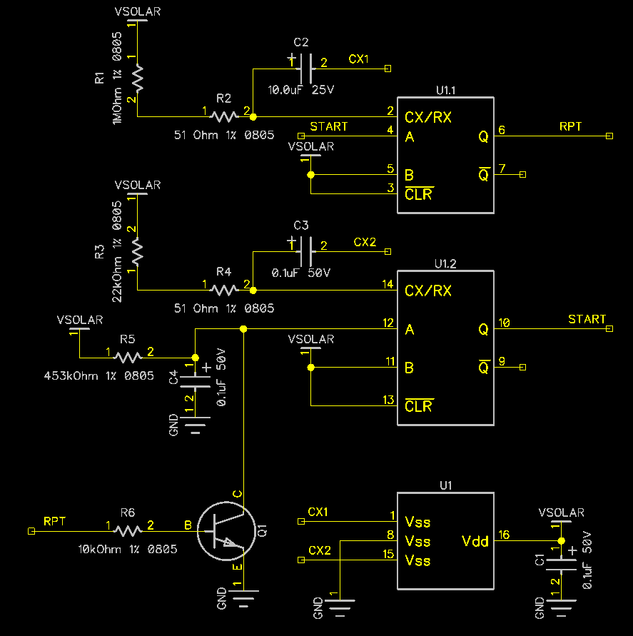
    Being that they are mono-stable multivibrators, I had to devise a way to retrigger each multivibrator one after the other. The first multivibrator had a long period to simulate the long duty cycle, and the second had the short period to turn the RT8299 off.

    After some tweaking, and realizing that the maximum allowable period supported by the IC is 10seconds, I got it to work. Rough schematic looks like this:

    The astute observer will notice just how similar this is in implementation to the internals of a 555 timer.

    As you could imagine, while a fun exercise in playing with 1970's technology, the large number of external passive add up to an impressive cost: about $0.17. Add this to the $0.14 for the IC itself, and you find that the total cost of this solution is $0.31, the same-ish price as the 555 timer or the PIC10F200. Hardly making progress here.

    I'm very close to eliminating the need for a microcontroller, but this timing circuit requirement sure is getting in my way. More to come.

  • We don't need no stinkin' DAC

    Jonathan Bruneau07/07/2016 at 01:53 0 comments

    Nor do we need ADCs either none.

    I want a cool hat like that!

    Turns out, with some clever wizardly, I figured out a way to get rid of the DAC and the ADC to make this MPPT power supply. "How and why" you may ask? Let me start with the why.

    My current implementation uses the PIC16LF1704, and I'm paying a whole $0.75 for it (really, it's $0.88 because of the mandatory LDO used to power the PIC's VDD rail). And for what? A OpAmp, comparator, a ADC, and a 8bit DAC, and a really dead simple algorithm that maps a solar panel open voltage ADC reading into a DAC setting, followed by a long waiting period before turning off the RT8299 and sampling again.

    Yeah, I put some fancy code to have the DAC output vary to have the MPPT output exactly track the exact MPP voltage, but that's otherwise a lot of money for something so simple. And since I'm trying to cut cost close to $1, I'm trying to find ways to take out the PIC16.

    It then dawned on me that the DAC+ADC+Algorithm are not needed in order to calculate the proper Vref needed on the negative input of the OpAmp (see this log for more explanation of Vref). Instead, I could build a peak detector, and properly condition the output to act as the Vref input to the OpAmp.

    In other words, instead of this (current method using internal PIC16LF1704 OpAmp):

    Do this:

    With the right combination of RT and RB, a open-circuit VSOLAR can be transformed into the same form that the DAC would normally output.

    There's a nice bonus of using this MCU-less solution: I don't need to pay the cost for a LDO. There's plenty of OpAmps that can go up-to 24V for plenty cheap.

    The trick, as it turns out, is timing. In order to get the open-circuit voltage of the solar panel, I need to turn the RT8299 off (i.e. set the enable pin low), and to do that, I need a timing circuit. The timer requirements are somewhat unique: it has to be a square wave with a pulse width must greater than 99%, with a period much greater than 10 seconds.

    But before I got too excited, I first wired up a breadboard with the new OpAmp hookup, using me (a human) as a timer to energize the sampling capacitor C3 with the open-circuit voltage. And boy does it work.

    So now I have to find a proper timing solution. I've already experimented with some timing circuits (namely the famed 555 timer), but I haven't gathered all my thoughts on it yet, so that's a story for another day.

  • If it ain't broke, don't fix it.

    Jonathan Bruneau05/07/2016 at 20:40 3 comments

    Good news, and bad news.

    But, first and foremost, I've returned from my long travels in Europe and started working on this project again. The nice thing about vacation is that, if you time it right, the PCBs fab themselves while you're gone lounging on a beach chair enjoying Pina Coladas (my vacation was similar, just without the Pina Coladas, nor the beach chairs).

    So, for the good news, I got the improved PCBs, stuffed a board, it runs great. This is the top.

    Top of PCB

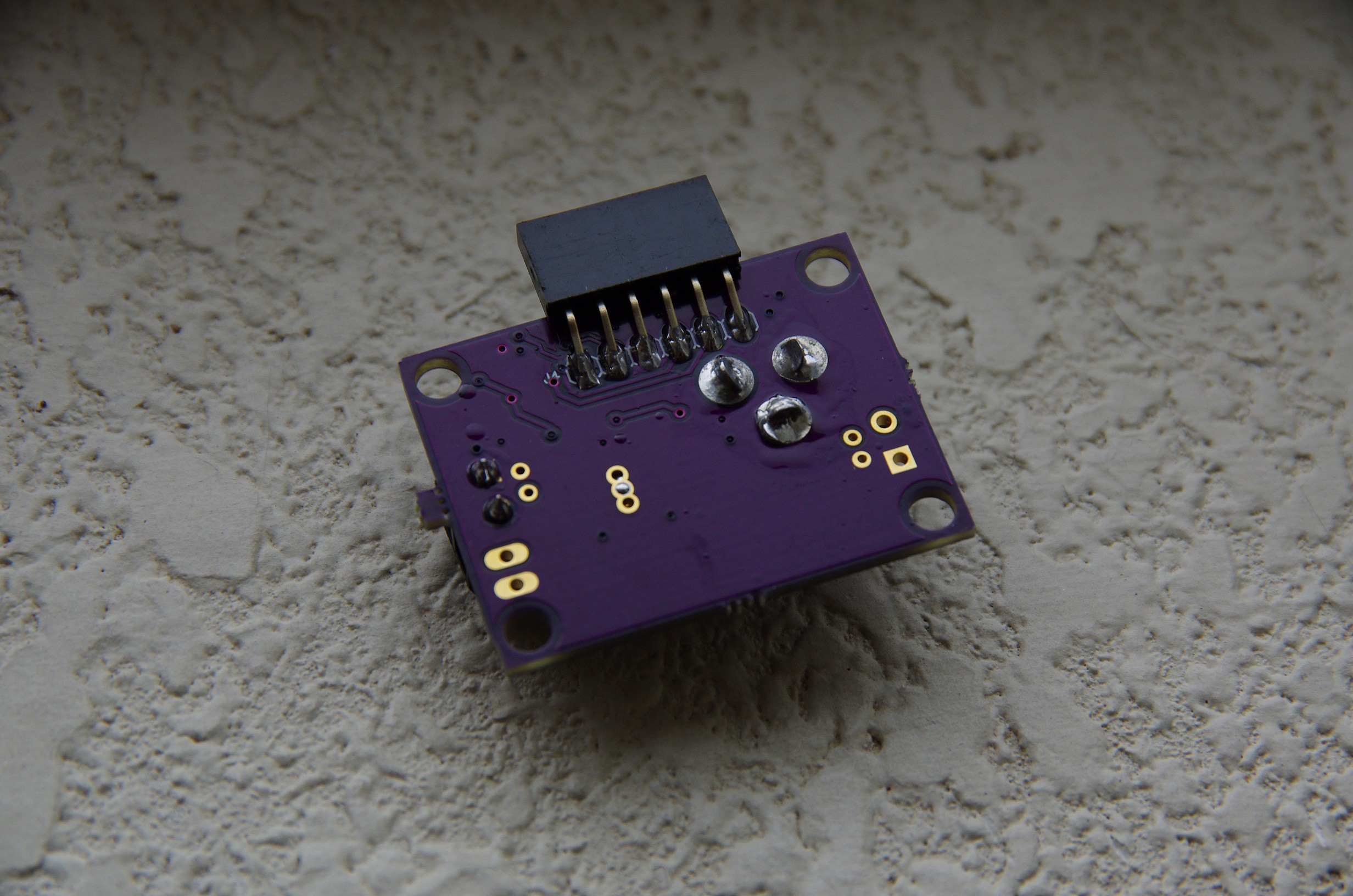
    And the bottom. Do note that the programming header (that right angle 0.1" 6pin header) doesn't need to be stuffed if the board gets programmed just once. A harness + pogo pins could program it just the same while keeping the back free of components.

    Bottom of the PCB

    Better yet, you can get the PICs preprogrammed from Microchip, and so the boards wouldn't even need to be programmed in the first place. Neato.

    This is all good news, so what's the bad news?

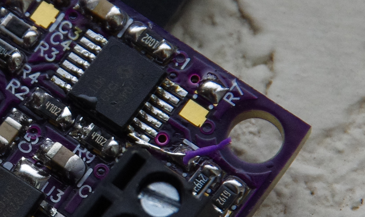
    Well, in my infinite wisdom, I "retrofited" the pinout of the PIC16LF1704 to make the board easier to layout, and in doing so, messed up one of the pin assignments. The astute observer will have noticed a blue-wire between a pad and a pin on the PIC16 in the first picture on this post. In case you don't believe me, here it is, in all it's glory.

    The shame.

    So there. Now I have 13 boards (3 from OSHPark and 10 from DirtyPCB) with this defect. Good news is the fix was incredibly simple to make, so I should be getting me some newer better PCBs in the near future.

    So, let's recap the total BOM cost.

    Component$/unit (1000)# UnitsTotal Cost
    PIC16LF1704$0.75001$0.7500
    RT8299$0.37751$0.3775
    AP2204K-3.3TRG1$0.13861$0.1386
    TYS60456R8M-10$0.15701$0.1570
    SBRT3U45SAF-13$0.11331$0.1133
    Resistors$0.004510$0.045
    22uF 6.3V$0.05232$0.1046
    10uF 25V$0.03572$0.0714
    Other Capacitors$0.01656$0.099
    PCB (DirtyPCB)$0.561$0.56
    Grand Total$2.4164

    This is respectable. Attach this power supply to a 2.5W solar panel and the $/W goal is achieved.

    I think there's more room to reduce cost/watt, but I might have to do so by making a new board that accepts multiple solar inputs on a single board. More on that later.

  • More GNDs are Happy GNDs

    Jonathan Bruneau02/07/2016 at 05:44 0 comments

    Small update.

    I've been playing with the PCB layout for the PIC16LF1704+RT8299 solution. I wanted to accomplished three things:

    1. Provide a better GND plane for the high-current path.
    2. Make the board smaller.
    3. Keep it to two layers (for cost reasons).

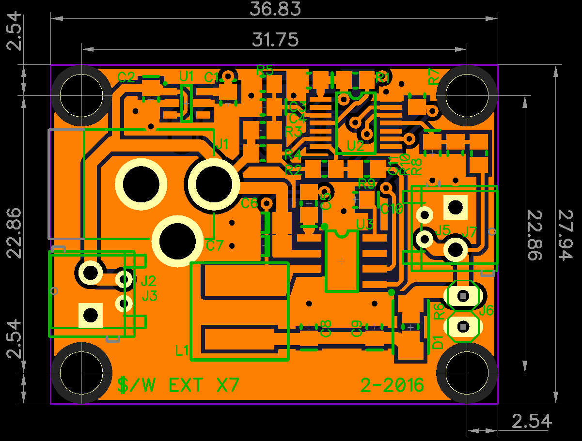
    It took some doing, but I got it. Here's L1.

    And here's L2 (notice the nice GND across the middle of the board).

    Satisfied, I ordered it through OSHPark and DirtyPCB. The latter fab house was picked because of the $0.56 I can get in volume, compared to the $1.60 from OSHPark. Plus, the boards come in red (that's got to count for something). We'll see how they compare to one another.

    Hell, if this board works out, we might have ourselves a winner.

  • The Venerable PIC12F1571

    Jonathan Bruneau02/03/2016 at 06:45 0 comments

    In a previous project log I mentioned the possibility of using the PIC12F1571 with an external OpAmp as a lower cost replacement for the PIC16F1704. It's not a huge cost savings, 20cents-ish, but it's enough to make my ears perk up.

    So, I tried it.

    Exact same circuit as the one prototyped in this project log, except the OpAmp is external.

    It works, it runs. So mission accomplished, right?

    Well no. There's an important difference between the PIC12F1571 and the PIC16F1704 that's causing the PIC12 to under perform: the Digital to Analog converter (DAC).

    The DAC is used to set the MPP voltage, which the RT8299 then regulates to (see this project log with an explanation of how this works). On the PIC16, we are graced with an 8bit DAC. This gives us 256 different solar operation voltage points. That is to say, for a maximum input of 24V, we have a resolution of:

    In other words, once we measure the open current voltage (Voc) of the solar panel, we can set the DAC setting to be within 0.09V of the MPP. Thats' really good.

    The PIC12, on the other hand, only has a 5bit DAC, so 32 different values. For a 24V input range, this gives us:

    This is sad, and for 5V panels, it's a deal breaker.

    Think about it, if the Voc of the panel is 5V, the MPPT is 4V (80% of 5V). With a resolution of 0.75V, we'd either get the panel to operate at 4.75V or 3.25V. The former is barely exercising the solar panel, the later runs the board really close to the under-voltage lockout of the RT8299. Neither scenario are good. We want 4V.

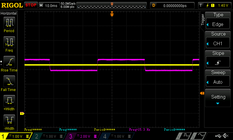
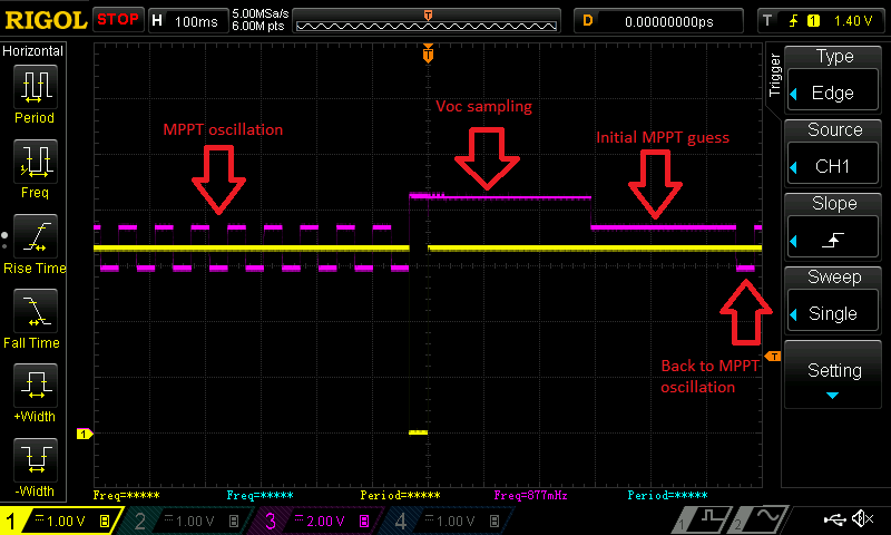
    This oscilloscope plot illustrates the problem quite well. It was captured while connected to a 9V solar panel, which at the time, was generating a Voc of about 8.4V. The Magenta line is the voltage of the solar panel, the yellow line should be ignored (it's the enable pin of the RT8299, which doesn't illustrated much in this case).

    Let me explain the plot above.

    The MPPT algorithm works by first trying to guess the correct DAC value to set in order to achieve the desired MPP voltage, subsequently sets it, and then adjusts the DAC until the correct final MPP voltage is obtained (since I have an MCU I can do neat things like that). In the plot above, the MPP voltage is between two voltage points that can be set by the DAC, and so the algorithm constantly oscillates between the two voltages, never reaching the desired MPP voltage.

    This longer capture shows this whole process. Again, the magenta line is the solar voltage, and the yellow line is the RT8299 enable pin.

    The poor PIC12: never able to reach it's goal...

    So, where does this leave me? Two options:

    1. Try to use the PIC12F1571 awesome 16bit PWM and a LPF to generate a pseudo 8bit DAC.
    2. Stick with the PIC16F1704.

    I can tell you that I already tried option 1, and there's quite a few problems in making it work. Two noteworthy issues: settling time and linearity, but I won't go in much more details about that. The truth is, at this point, I'm trying to do a hack of a hack, and hacks^2 never make me feel comfortable.

    I might wake-up with another way to properly use the PIC12F1571, but most likely I'll just come up with more bad ideas. So I'm sticking with the PIC16F1704 for now. The next step is to redo the layout of the last board. I'll post my progress as it happens.

    Until then.

View all 21 project logs

Enjoy this project?

Share

Discussions

Raphael Pereira wrote 11/07/2024 at 09:24 point

Hi, you do very nice job. Can you please share your source code? I'm very interesting to se how you implement the thing.

  Are you sure? yes | no

Paul Robertson wrote 08/11/2018 at 01:40 point

Any updates you can share?

  Are you sure? yes | no

Jonathan Bruneau wrote 08/14/2018 at 04:47 point

Funny you should mention that.  I'm currently working on an updated log as we speak.

  Are you sure? yes | no

prithivi raj wrote 08/05/2017 at 20:53 point
needed help. implementing mppt in this sepic dc
vin:10v to 35v
vout:5v to 25v
iout:15a
uc3843 based boost schematic.
https://postimg.org/image/ihg0qiu2j
https://postimg.org/image/bijww5o4l
https://postimg.org/image/rjbew4b3f
https://postimg.org/image/xfhdclstx/

  Are you sure? yes | no

mr.jb wrote 07/22/2017 at 13:44 point

Please let me know when it's available to buy ! ( Tindie ? )

  Are you sure? yes | no

Paul Robertson wrote 07/05/2017 at 06:29 point

Can't wait for the next installment.....

  Are you sure? yes | no

Albert Phan wrote 03/23/2017 at 18:24 point

Just discovered this project and read through some of your logs. You did a exceptional job documenting and explaining your clever hacks! I look forward to reading the rest of your logs and seeing where this project goes. I hope to help in some way.

  Are you sure? yes | no

Albert Phan wrote 03/28/2017 at 21:49 point

Just finished reading your logs. Great read. I'm looking to create an MPPT controller capable of up to 400 Watts for our remote sites. Your logs will definitely help with that. It seems like there aren't many MPPT products that work around that wattage. For smaller home stuff, your project would definitely by ideal. Would you happen to sell an extra prototypes you might have? I would love to test some of them. 

As for the 12V question. Yes, definitely have the option to do 12V as a lot of remote solar systems will be using 12V lead acids batteries.

  Are you sure? yes | no

Jonathan Bruneau wrote 03/29/2017 at 02:10 point
Thanks Albert, I'm glad you like my logs.  If anything, it's been a really good documentation platform for just myself: I refer back to my posts frequently.

At higher power, MPPT products move more towards industrial offerings.  At the very least, $250ish per MPPT controller. 

I was suspecting the 12V answer as well.  It's hard to have a buck only solution, and it's hard to have a boost only solution as well.  The permutations of configurations is quite large, and forcing a one way (down/up) conversion is a tough sale.  Along these lines, I'm in the process of building a new supply (a different kind of hack).  If that one works acceptably well, I'll put it out there.  If you PM me your address I'll send you one of the first ones.

  Are you sure? yes | no

Stefan wrote 02/14/2017 at 12:09 point

Hi Jonathan, recently discovered your project. It Is fun reading. Regarding the 12V, yes many panels are 32..36 cells. These are called 12V panels.


In general for a panel goes 0.6V per cell for Voc and Vmpp is at 0.5V per cell. That said this is a hint for you to design MPP converter in a budget way. It is called a constant voltage MPP system. It is very suitable using a standard buck without controller. 
Say you have a 6V panel, what they mean is that it is 12 cell panel. This means that Voc is near 7,2V and that Vmpp is 6,0V. So when you connect this panel to a battery the FB control to buck must be such that the panel voltage is 6V (or any preset voltage depending on the number of cells in your panel).


You can use a difference amplifier with an offset in the FB loop. It must be dimension-ed such that Vout =Vfb=Vref when Vpanel=Vmpp. With Vmpp the fixed voltage belonging to your panel and the minus term of the difference amplifier must be your panel voltage. What will be happening is that the duty-cycle of the buck is regulated to match the battery to the panel. Say you have a 3.6V battery, than with this control circuit the DC will be 3.6/6=0.6 the current to the battery will be 1/0.6=1,67 times the current that comes from the panel and you will be charging the battery at the panel MPP. 


Ok, you can say the Vmpp is dependent on temperature and illumination and sure it is, but this effects are reasonably small. Delta P / Delta Vpanel is small near Vmpp, so that is why it reasonably to take Vmpp 0.5V/cell.

  Are you sure? yes | no

Jonathan Bruneau wrote 03/29/2017 at 02:28 point
It's interesting you mention this.  I've been thinking recently of certain optimizations that can be performed if the solar panel is matched with the MPPT controller.  In those situations, as you stated, certain assumptions can be made that can substantially save on complexity and cost.  

I really like your difference amplifier idea.  It an elegant way to regulate both the battery and MPP using a single linear device.  And when matched with a solar panel with a known MPP, all you would need is the buck + OpAmp.

Thanks for sharing your ideas.  The more time goes by, the more I realize I've but scratched the surface of this problem domain.

  Are you sure? yes | no

Stefan wrote 04/03/2017 at 19:39 point

Hi Jonathan, if you want I could set-up a simulation proof of concept. Using an integrated buck converter from e.g. LT because it runs easily in LT spice. If that runs another IC could be use in a final design. 

  Are you sure? yes | no

Artful Codger wrote 02/03/2017 at 16:03 point

"Do I need to care about 12V output? Maybe this is something you can tell me."

Major users of solar charging are marine, recreational vehicle, and standby/emergency systems, and the vast majority of these are based on 12v. So I would say... yes. :-)

  Are you sure? yes | no

Jonathan Bruneau wrote 03/29/2017 at 02:19 point
Somehow I missed this comment.  Duly noted.  Thanks for the hint.

  Are you sure? yes | no

chris myers wrote 12/10/2016 at 15:59 point

Out of curiosity, do you have a complete schematic and BOM posted somewhere so that I can try to find the through hole equivalents and build it myself? 

  Are you sure? yes | no

chris myers wrote 12/10/2016 at 17:46 point

... Or if they're not too expensive, I'd be willing to buy a prototype board too since it sounds like they're working :) 

  Are you sure? yes | no

Jonathan Bruneau wrote 02/03/2017 at 06:06 point
Somehow I missed this message.  My apologies for the overly tardy response.

I don't have any assembled prototype boards anymore.  Most were given away, some got lost, and other got destroyed!  

I'm in the process of brewing another, improved version of this thing.  I can order a few extra and send them your way.  PM me your address and I'll send you some when the next batch is in my hands and assembled.

  Are you sure? yes | no

chris myers wrote 12/03/2016 at 13:40 point

So... I love the idea for this project, and would really like to build one myself. But my hands aren't steady enough to do fine soldering. Do you know if this would be possible with through-hole components, or if you'd be willing to sell boards after you're satisfied with the project? 

  Are you sure? yes | no

Jonathan Bruneau wrote 12/08/2016 at 05:02 point

Hi Chris.  Thanks for your interest!  

Selling these boards is certainly the plan,  but I like your idea of making a through-hole version as well.  If anything, it would make for a fun kit to assemble.

The nice thing about this project is that the concepts are fairly general and can easily be retrofitted to accommodate different components (i.e. components offered in TH).  I was also thinking of changing the form factor such that it readily plugs into a breadboard as a 7805 replacement.  My PCB squeezing skills will be challenged.

  Are you sure? yes | no

chris myers wrote 12/09/2016 at 02:14 point

That would be a lot of fun putting one of these together... A kit would be awesome :)

Something else that I like about the idea is that it gives the opportunity to over-build as well, with more robust components - when you buy something mass-produced, you're kinda stuck with whatever the manufacturer decided to include :P And by being able to breadboard the project, you can swap components around and really customize the design. 

I'll definitely be interested to see how things progress, and want to try to build one myself :) 

  Are you sure? yes | no

georg ottinger wrote 08/13/2016 at 21:42 point

very inspiring project - For cheap timing circuits may be Silego GreenPak could be an option. I think the SLG46108V - 8 pin part could be used to generate short impulses (few ms / tens of ms) every 10 (or longer) s. And is very flexible about the intervals. Cheap is relative but this part goes down to 0.135 USD in 9k quantities. max. Vsupply is still 5.5 so no skipping on the LDO on this route. https://postimg.org/image/bh7yh197d/

  Are you sure? yes | no

Jonathan Bruneau wrote 08/14/2016 at 20:43 point
Thanks!

Aren't those GreenPaks cool?!?!  I spoke with Silego's FAE a few months ago, and these things are a great "bang-for-your-buck".

The GreenPak5 are also reprogrammable over I2C, on the fly!  It's like having a tiny FPGA for a fraction of the cost.

If only they came with an OpAmp...

  Are you sure? yes | no

georg ottinger wrote 08/15/2016 at 18:38 point

I just wonder if a Comperator would do the job aswell ...

  Are you sure? yes | no

Clovis Fritzen wrote 08/04/2016 at 00:33 point

Hi, nice project!. I got so interested that I want to try it myself. Will you make the schematics available in PDF or Eagle any time soon? Thank you!

  Are you sure? yes | no

Jonathan Bruneau wrote 08/04/2016 at 02:57 point
Thanks Clovis.  I'm glad you have as much interest as I do with regards to this project.  

The intent is certainly to give out the schematics, BOM, and art when the circuit is done, but for now the design is still very much in flux, hence my hesitation.

BTW, I really like your battery-less computer mouse project.  I'll be keeping an eye on your progress.

  Are you sure? yes | no

mr.jb wrote 09/09/2015 at 04:26 point

Status on V2 board ?

  Are you sure? yes | no

Jonathan Bruneau wrote 09/09/2015 at 05:11 point

Just got the PCBs today, so should be working on the board soon.  Also playing with the RT8299 hack and should have some updates on that soon as well.

  Are you sure? yes | no

Valent Turkovic wrote 08/17/2015 at 17:09 point

Hi, this project looks awesome. How far are you from V1.0 on board and components? I would gladly build board on your specs and become a beta tester, but we are short on summer days so I hope it will be sooner rather than later...

  Are you sure? yes | no

Jonathan Bruneau wrote 08/18/2015 at 04:49 point

Hi Valent.  I'm really stocked as well for this project come to fruition.  I should have an updated project log with the juicy details soon, but the long and the short of it is that I'm in alpha going into beta on this next PCB spin.  If all goes well (no explosions) we're looking at 4-6 weeks.  Might be cutting it close, depending on how far away you are from the equator.  Fingers crossed.

  Are you sure? yes | no

[deleted]

[this comment has been deleted]

Jonathan Bruneau wrote 06/23/2015 at 04:25 point

I was going to make a breakout board for the ATSAMD10C13A, but if you have something already available I wouldn't say no.  If anything, I'd like to try the TCC peripheral of the ATSAMD to see how I well it would fit this project.

  Are you sure? yes | no

Atmel Corporation wrote 06/23/2015 at 11:59 point

Hey Jonathan! Send us a direct  message on here and we can take it offline. Happy to help you out! #PICKAtmel  

  Are you sure? yes | no

Jonathan Bruneau wrote 06/17/2015 at 21:40 point

Hi mr.jb.swe!  

Thanks for the suggestion.  I've looked at the ATtiny861A in the past but had discounted it as being too expensive, especially since I can get the same functionality out of the ATSAMD10C13A for cheaper.  It's too bad really: I do like the simplicity of the ATtinys.  My fear with the SAM D10 part is that they are significantly harder to configure.

The one catch to using a microcontroller for current sensing is that I'm limited to either low-side current sensing or high-side with voltage dividers.  The former can only be placed on the low-side of the buck regulator (which makes finding the MPP harder and requires more filtering), while the latter has some serious CMRR issues when the resistors are not perfectly matched.  There's no good answer, really, hence the challenge of this project.

Lastly, thanks for sharing the links.  I've seen a lot of hacks done before to get MPPT like functionality on the cheap, but they always seem to require a fair bit of tweaking to properly operate.  I want this MPPT controller to identify and track the MPP on it's own without any external intervention.  You could take the same MPPT controller and plug it in a 6V solar panel or a 12V solar panel with no HW change and get the same expected result.  

I didn't state these goals in the project description, so I'll update that section accordingly.

I know there's a solution out there, especially since a good deal of the functionality would be provided in SW, which costs $0 to manufacture.  It's just a matter of finding the right balance.

  Are you sure? yes | no

mr.jb wrote 08/01/2015 at 21:59 point

>using a microcontroller for current sensing is that I'm limited to
>either low-side current sensing or high-side with voltage dividers 

with a ATtiny861 ( differential gain ) you could put sense anywhere...

I think the cheapest solution is a RT8272 + ATtiny +  "wham bam regulation" ( using enable pin )

RT8272

http://tw.richtek.com/assets/product_file/RT8272/DS8272-02.pdf 


Veery cheap 1 $
http://www.ebay.com/itm/10PCS-Mini-DC-DC-Buck-Converter-Step-Down-Module-Power-Supply-For-aeromodelling-/201234570492?pt=LH_DefaultDomain_0&hash=item2eda83dcfc

And you could skip current sense and go for 80%  of open-voltage ( for solar panels ;-) since RT8272 is protected. 

With this approach you could afford a cheap display and still < 1$/W

( I'm planning to scale down my 1charger with this approach,,,,,  ;-)

  Are you sure? yes | no

Jonathan Bruneau wrote 08/04/2015 at 14:23 point

You know, that's not a bad idea at all.  
I've given it some thought last night as to how this would work, and the regulator would basically operate as a weird PFM regulator with "long pulse periods", which would be fine.  

My biggest concern would be the soft-start (SS) on the regulator.  If it's too long it would be hard to track the MPP as each On/Off cycle would spend most of it's time in the SS mode and not actually doing full regulation.  This would basically mean that the 3A output could never be achieved.

That being said, the part you've suggested covers a good 80% of the PCB I'm working on, and for that price, I'd be completely crazy not to try.  Hopefully placing a smaller capacitor on the SS pin will give desirable results.

Thanks for the great suggestion.

  Are you sure? yes | no

mr.jb wrote 06/17/2015 at 11:36 point

You could use an ATtiny861 with differential gain to measure current..

Other simple stupid approaches ( hack existing step down..)

http://www.fieldlines.com/index.php?topic=146685.0 

http://www.fieldlines.com/index.php/topic,144628.msg977808.html#msg977808

  Are you sure? yes | no

Similar Projects

Does this project spark your interest?

Become a member to follow this project and never miss any updates