Over the last few weeks I've been searching the web trying to find the right balance of parts and cost in order to meet or exceed the $1/W budget. I've compiled a long list of possible configurations in an Excel sheet (see sample below) and have narrowed it down to two options.

But first, allow me to tie up some loose ends.
Originally I had thought that driving a P-Channel MOSFET (PMOS) on the high side would help reduce on cost. While this is true, the cost difference between using a PMOS vs. an NMOS is only about $0.06/W. That is to say, having a half-bridge driver + NMOS is just slightly more expensive than using a PMOS with respective circuitry to drive it. This is true because driving a PMOS isn't as simple as doing something like this:

Image taken from Maxim's App Note 1158.
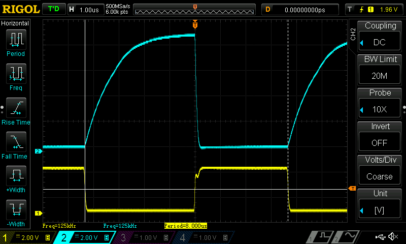
The reason this doesn't work is because the PMOS' gate has some capacitance associated with it, and so when the lower NMOS turns off, an RC circuit is formed between the pull-up resistor and the PMOS gate capacitance. In effect, this causes the PMOS to turn off slowly for large resistances and/or gate capacitances. Below is a capture I did of a PMOS of interest driven in this manner:

The yellow line is the NMOS gate input, and the blue (cyan?) line is the PMOS' gate. That long rise time on the blue line is the problem. The PMOS quickly turns on, but turns off rather slowly, which causes shoot through problem in synchronously rectified buck regulators, in turn affecting the regulator's efficiency.
I was able to get the PMOS to turn off quickly, but the resistor value needed to accomplish this was unacceptably large, thus voiding this simple circuit for synchronous buck regulator.
Of course, it is possible to drive a PMOS quickly using a more involved circuit, but for the same price I can get an integrated NMOS half-bridge driver. The one I'm currently eyeing is the NCP3420, and at $0.24/1000 parts, that's nothing to scoff at. Pair that with two DMN3404L-7 NMOS, and we're looking at a total BOM of $1.64 (includes microcontroller, current sensor, passives, etc.).
The half-bridge driver runs on 5V, so if we want our MPPT regulator to support 5V solar panels, then we need to add a charge pump to bring-up the voltage to 5V when the solar panel's voltage is lower. The cheapest reasonable regulator I could find was the MAX1720, bringing the new total to $1.88.
This is pretty good, and I'm currently layout out the board for this option.
There is, however, a possible second option. mr.jb.swe suggested using a buck regulator IC and tying the enable pin to a PWM coming from a microcontroller (MCU). In other words, instead of having a MCU drive a MOSFET driver IC, the MCU would drive the enable pin of a "all in one" ready made buck regulator. There are several advantages to using this method.
- It's considerably cheaper. For instance, using the RT8299 runs me at $0.33/1000 parts and would bring the BOM down to $1.53, or a savings of $0.35.
- It includes the half-bridge driver, the bootstrap diode for the driver, the NMOS fets, and a high-side current sensor with over-current protection.
- Being integrated, using this part would make the PCB smaller, which lowers PCB costs.
- Since all the work is done by the external buck regulator, the requirements for the MCU running the MPPT algorithm is substantially lowered. All the MCU needs to do is read an ADC channel and generated a PWM output. No comparators nor fancy PWM are needed, and the MCU can be clocked at a much lower frequency.
- The integrated regulator has over-temperature limits included, which eliminates the need for the MCU to do this work.
The one catch to this option is that there are start-up costs associated with each off/on cycle of the enable pin on the external buck regulator. That being said, I *HAVE* to try this option, as it is by far the most cost effective solution and I'd be crazy not to give this a whirl. Who knows: perhaps the savings will outweigh the start-up cost.
More to come.
 Jonathan Bruneau
Discussions
Become a Hackaday.io Member
Create an account to leave a comment. Already have an account? Log In.
OperaHouse: is describing "Wham Bam" regulation ( enable pin ) with LM2596 here
http://www.fieldlines.com/index.php?topic=146685.0
You have one more option, manipulating the feedback pin
This is the only regulator I've seen exposing it so clearly to the user
Three diodes connected to FB ( user "PWM", CC, CV )
http://www.prodctodc.com/dc-4530v-to-0830v-dc-buck-step-down-converter-pwm-constant-current-led-driver-p-159.html#.VcHbFPlkaew
OperaHouse: "operate like a two input type"
http://www.fieldlines.com/index.php/topic,144628.msg977808.html#msg977808
The best with fooling the feedback sense is it can be done to almost all DC/DC converters... As I see it MPPT could be accomplished by dynamically changing the CC ( MCU + SPI controlled resistor !? )
For a universal MPPT you should consider that TEG, dynamo behaves different to solar panel ...meaning you will probably need a current sense ;-)
http://www.eetimes.com/document.asp?doc_id=1279330
A bonus; would be the option to put several MPPT in parallel
( consider Vref, sense....or just OR them together relying on CC )
Are you sure? yes | no