Good news, and bad news.
But, first and foremost, I've returned from my long travels in Europe and started working on this project again. The nice thing about vacation is that, if you time it right, the PCBs fab themselves while you're gone lounging on a beach chair enjoying Pina Coladas (my vacation was similar, just without the Pina Coladas, nor the beach chairs).
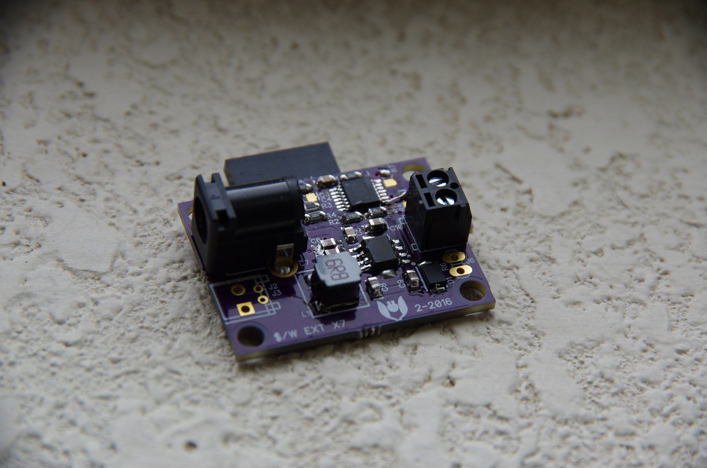
So, for the good news, I got the improved PCBs, stuffed a board, it runs great. This is the top.

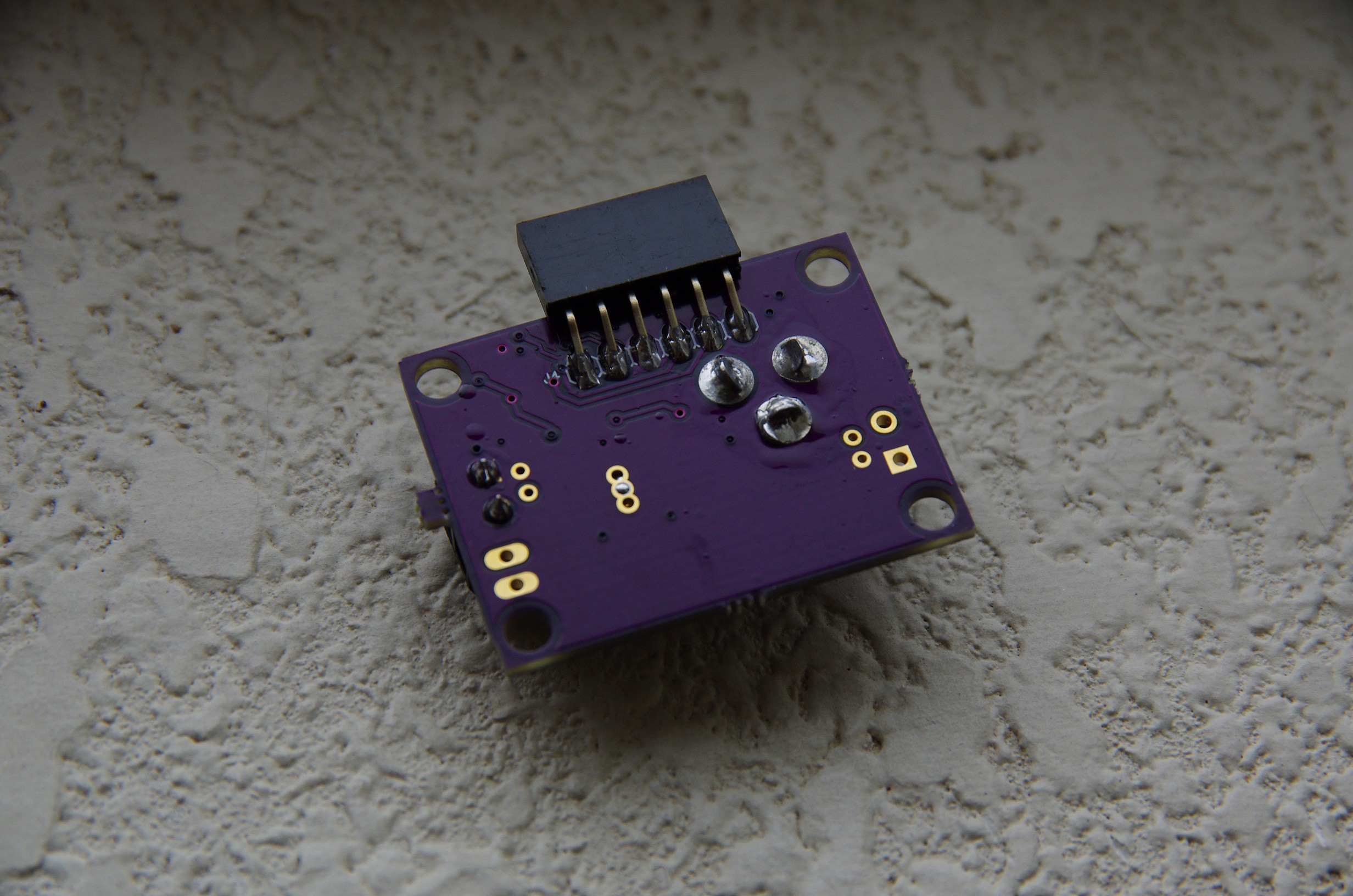
And the bottom. Do note that the programming header (that right angle 0.1" 6pin header) doesn't need to be stuffed if the board gets programmed just once. A harness + pogo pins could program it just the same while keeping the back free of components.

Better yet, you can get the PICs preprogrammed from Microchip, and so the boards wouldn't even need to be programmed in the first place. Neato.
This is all good news, so what's the bad news?
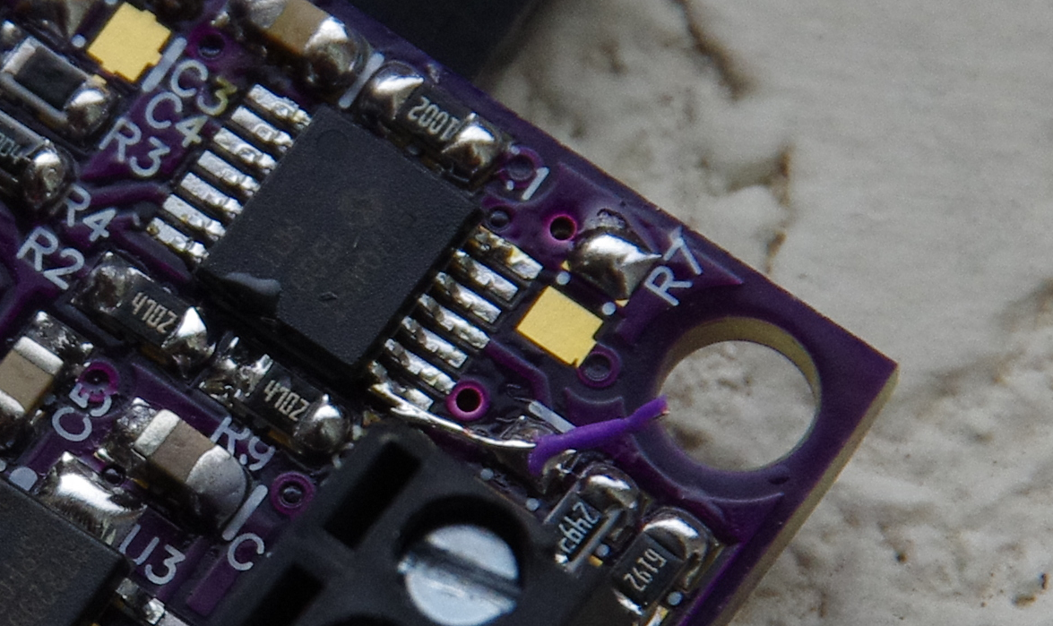
Well, in my infinite wisdom, I "retrofited" the pinout of the PIC16LF1704 to make the board easier to layout, and in doing so, messed up one of the pin assignments. The astute observer will have noticed a blue-wire between a pad and a pin on the PIC16 in the first picture on this post. In case you don't believe me, here it is, in all it's glory.

The shame.
So there. Now I have 13 boards (3 from OSHPark and 10 from DirtyPCB) with this defect. Good news is the fix was incredibly simple to make, so I should be getting me some newer better PCBs in the near future.
So, let's recap the total BOM cost.
| Component | $/unit (1000) | # Units | Total Cost |
| PIC16LF1704 | $0.7500 | 1 | $0.7500 |
| RT8299 | $0.3775 | 1 | $0.3775 |
| AP2204K-3.3TRG1 | $0.1386 | 1 | $0.1386 |
| TYS60456R8M-10 | $0.1570 | 1 | $0.1570 |
| SBRT3U45SAF-13 | $0.1133 | 1 | $0.1133 |
| Resistors | $0.0045 | 10 | $0.045 |
| 22uF 6.3V | $0.0523 | 2 | $0.1046 |
| 10uF 25V | $0.0357 | 2 | $0.0714 |
| Other Capacitors | $0.0165 | 6 | $0.099 |
| PCB (DirtyPCB) | $0.56 | 1 | $0.56 |
| Grand Total | $2.4164 |
This is respectable. Attach this power supply to a 2.5W solar panel and the $/W goal is achieved.
I think there's more room to reduce cost/watt, but I might have to do so by making a new board that accepts multiple solar inputs on a single board. More on that later.
 Jonathan Bruneau
Discussions
Become a Hackaday.io Member
Create an account to leave a comment. Already have an account? Log In.
[this comment has been deleted]
Glad you liked it. More to come!
Are you sure? yes | no
Great project man. Thanks for taking the time to share it. Curious what it cost to get the boards made and why you did 3 boards from oshpark and 10 from dirty pcb?
Are you sure? yes | no
Thanks! Glad to hear that this project gets some interest.
As for 3 and 10 boards, these were the minimum quantities needed in order to complete an order. I would have ordered fewer if I could.
As for cost, I haven't really looked into assembly cost yet. I still have to do a lot of testing to make sure the power supply works as intended, and that, over long periods of time. More on this later!
Are you sure? yes | no