-
Bad Ideas
01/29/2016 at 07:12 • 5 commentsSo I've been fretting over saving money on this project to get the Bill-of-materials (BOM) cost down.
I've had a fair share of ideas cross my mind. Many I'm too ashamed to post on this blog, but three stuck out as being somewhat plausible.
- Getting rid of the MCU altogether and replacing it with a 555 timer and a clever solar open-voltage (Voc) sampling circuit. Not only are 555 timer extremely cheap, but they can operate up to really high VDD voltages, thus dispensing the need for the LDO.
- Replacing the DAC with a PWM and a low-pass filter (LPF).
- Simulating the OpAmp in software.
I ran some numbers on option 1 (MCU swapped for a 555), and it turns out that after I re-add all the parts offered by the MCU (OpAmp, comparator (or crappy OpAmp based comparator), Voc sampling circuit), the cost difference is pretty small. It's about 20cents cheaper than the PIC12 + External OpAmp solution (which was already cheaper than the PIC16 + internal OpAmp solution).
There's another catch on option 1. The cheap 555 timers have an astonishing 10mA of quiescent current (Iq). Yikes! A more reasonable 555 timer (Iq = 65uA) costs about 22cents. Once you add this to the cost for the external comparator and Voc sampling circuit, the difference between a 555 and a PIC12 + LDO is pretty small: less than 10cents.
So the 555 timer isn't the best of ideas.
Option 2 is somewhat promising. If I could find a way to eliminate the need for a DAC by replacing it with a PWM + LPF, then a new set of cheaper MCUs can be used to run the MPPT algorithm.
How much money could I save? Well, compared to the PIC12F1571, about 8cents... tops. Not much of an improvement.
Option 3 was a stretch, but the idea was that if I could directly tie the output of the DAC to the FB pin of the RT8299 and emulate the OpAmp in software, I wouldn't need the OpAmp, saving me a whole 10-20cents.
Well, I tried it. I had the calculations all precomputed in a giant lookup table to make the code run as fast as possible, set the sampling rate of the ADC to the highest value possible, and let her rip.
Boy did that not work... at all. I figured I needed to run the simulated OpAmp at 500kHz, the same speed at the RT8299, but I got closer to 10Hz.
In hindsight, this makes sense. The fastest the PIC will go is 32MHz, but it actually executes instructions at 1/4 of that, so 8MHz. To get 500kHz, that leaves me with 16 instruction cycles to fetch the ADC value, lookup the corresponding "OpAmp" value in the lookup table, write it to the DAC, and let the DAC settle to it's new value.
Basically, not nearly enough time, especially since the PIC needs to run the actual MPPT algorithm proper, which eats away at my precious 16 instruction window.
By far, option 3 was the worst idea of them all. I wouldn't be surprised if, as you were reading this project log, you thought of something along these lines.
![]()
-
There's Always a Penny to Pinch
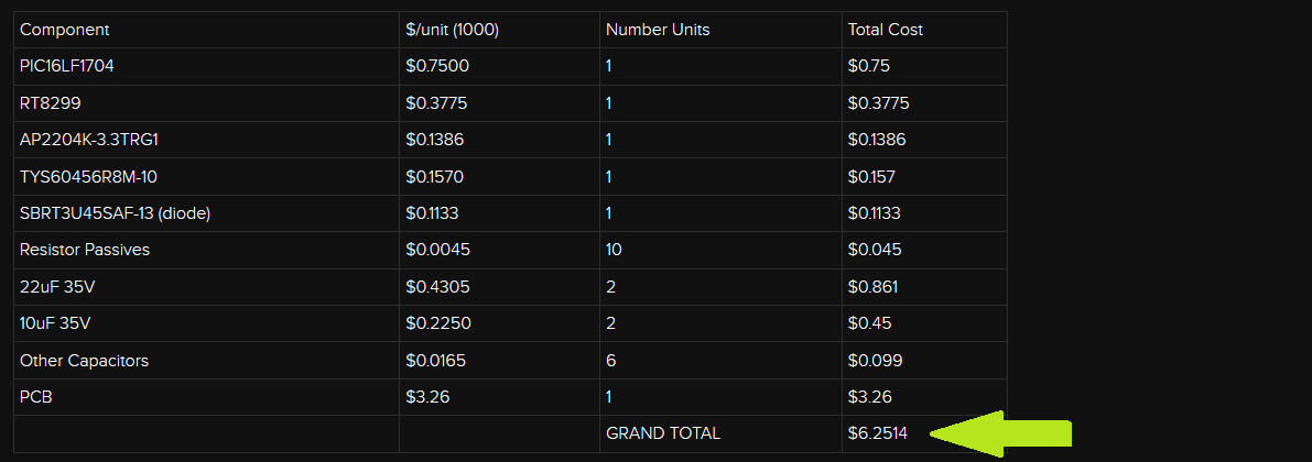
01/14/2016 at 02:49 • 2 commentsAccording to my Bill of Materials (BOM) from my last project post, building up a board cost about $6.
That's good, but I can do a lot better. It's time to penny pinch (the person below has mad pinching skills).![]()
![Man, this person can pinch!]()
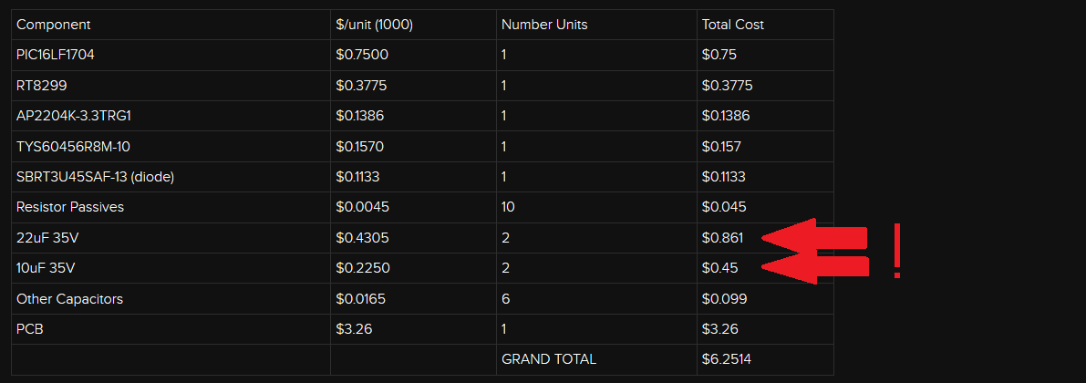
I'm loosing a lot of money on capacitors: a whole $1.31! The truth is, those costs come from the high voltage requirements imposed on those caps to support the max 24V input. Or is it?
First, I made a stupid mistake. The 22uF output capacitors don't need to be high voltage as they are on the output of the buck regulator. I can thus make a far more appropriate capacitor selection. Two seconds of searching gave me a $0.05 part: the CL21A226MQCLQNC. So just there I cut out $0.76!![]()
As for the input caps, I had a hunch I could do better than $0.22 a pop. It took a little bit more doing, but I found a 25V cap that just might do the trick: the GRM21BR61E106KA73. At $0.05 each, I save yet another $0.35. I could save even more money if I chose the 0805YD106KAT2A, but rated at 16V, that's not a limit I'm willing to impose (yet).
By just changing the capacitors, I saved a total $1.08! This brings down the total to just north of $5, so to get a $/W, you would only need a 5W panel.
There's still room for improvement. If I forgo the OpAmp integration offered by the PIC16LF1704 and replace it with an external OpAmp, I could surprisingly save some more cash. The PIC12F1571 has everything I need minus the OpAmp, but sells for *way* less than the PIC16LF1704, $0.41 vs. $0.75. An acceptable external OpAmp, such as the AZV321KTR-G1, run for $0.12 each. The grand total for MCU + OpAmp would be $0.53, a $0.22 savings. When you're counting pennies, this adds up to be quite a bit.
With all these savings combined, we're down to $4.9514.
Option two with the MCU is to use the PIC16F753 that I am reluctant to use in the first place. On the flip side, it has the integrated OpAmp and it removes the LDO. At $0.66 each, the total savings off the BOM would be $0.22, same as using the PIC12F1571 with external OpAmp.
Can I do better? Sure I can. If I'm willing to get a higher DCR inductor and a higher dropout LDO, I could save a little bit more. About a dollar or so.
Truth be told, the biggest cost sink is the PCB. I'm not sure how, but I've got to find a way to make it smaller. That will make the biggest impact. So for now I'll stay the course with the PIC16LF1704 (and apply the cost savings from the new capacitors) and try to cut costs on the PCB.
-
RT8299 Hack Progress
01/13/2016 at 06:42 • 0 commentsIt's always a good day when PCBs make it to your mailbox. There's an inner child that gets excited with the prospect of getting new toys to play with.
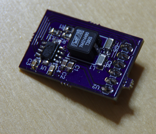
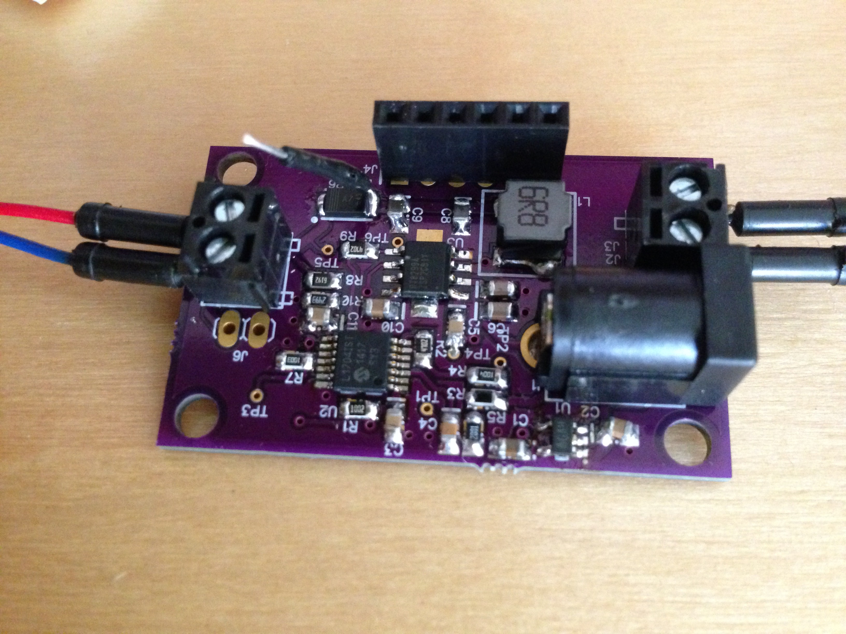
Two days ago was no exception. This latest batch implement the Proper RT8299 hack on a PCB (see this post for more details). Without much hesitation or interruption (minus a mandatory tea break), I soldered it all up, and it works.
I've definitely done better soldering jobs...
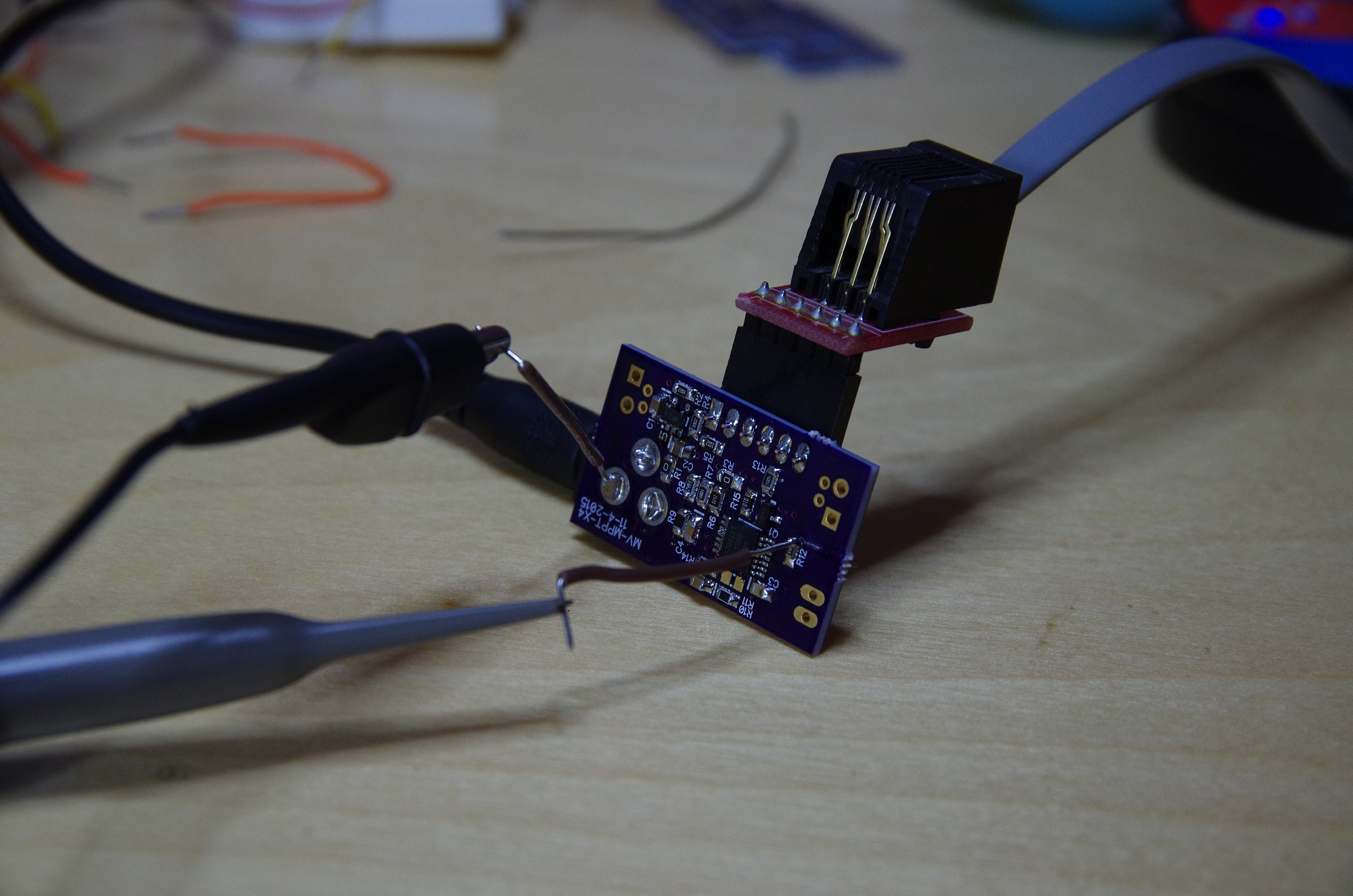
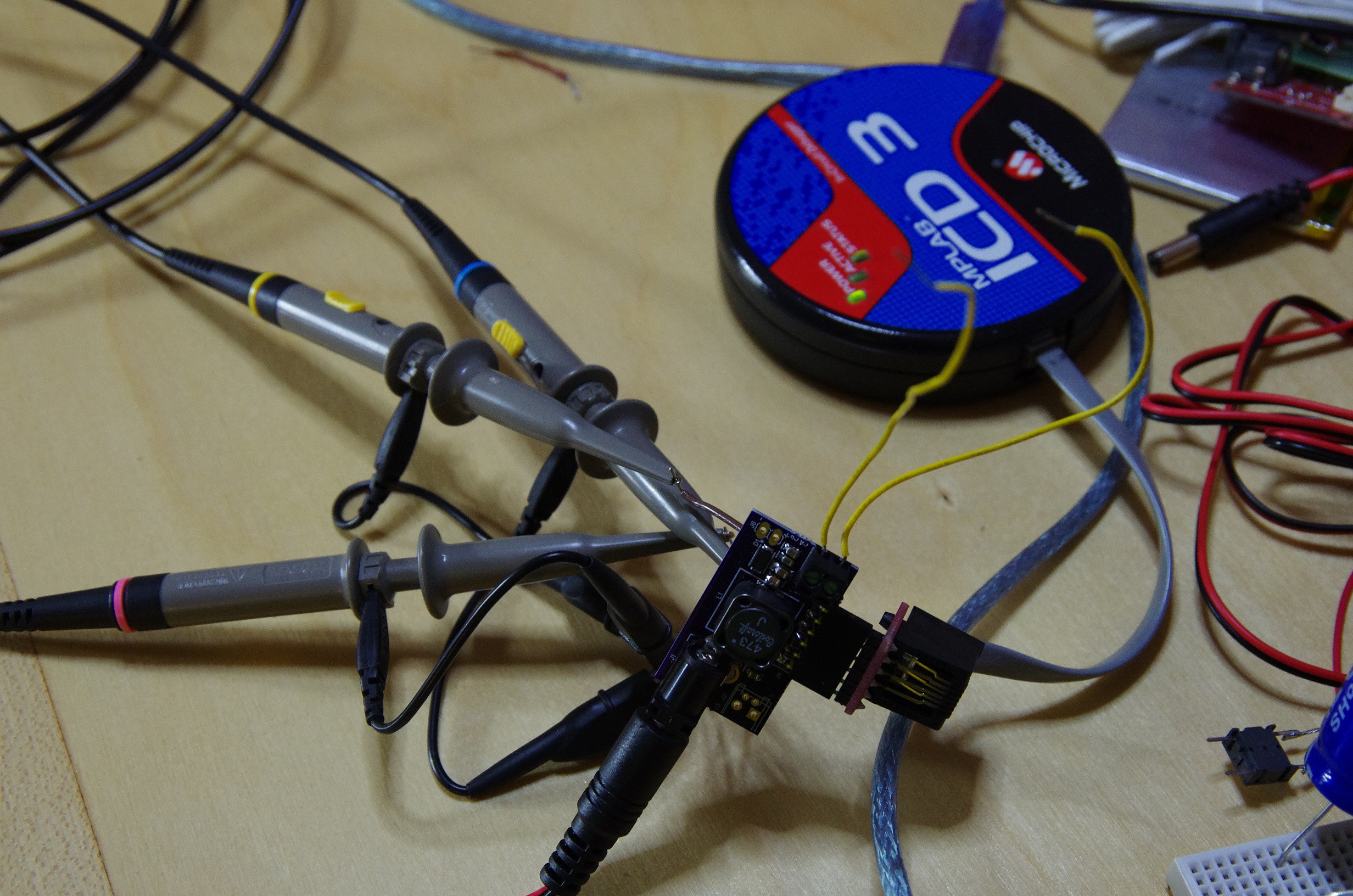
Operating voltage for this MPPT is 3V-24V with a maximum current of 3A (limited by the RT8299). The total quiescent current is 1.5mA-ish at 3.3V, so 4.95mW is lost to the MCU+RT8299. I did some evil tricks on the MCU to cut down the quiescent current to 500uA, and I could get it down some more with some prodding but figured it was good enough for now.
Anyways...
Since the last post of the subject, a lot of things have changed with this design that are noteworthy
First, I opted to use the PIC16LF1704 for the MCU. It has an 2 integrated OpAmp, 2 comparators, a 10bit ADC, a 8bit DAC, and a bunch more, all for $0.75. And so, with a single component, I have all I need to trick the RT8299 to regulate the solar voltage input. I came very close to using the PIC16HV753 (same price as the PIC16LF1704) because of the MCU's integrated shunt regulator, which would remove the need for an external LDO. Truth is, the internal reference's voltage of the PIC16HC753 isn't high enough to properly trick the RT8299, so I opted to stick with the PIC16LF1704.
Ok, actually, I lied, it would work, but the reference voltage of the RT8299 and the PIC16HV753 are pretty close to one another, and I prefer having some wiggle room. It's a cost improvement that I can look into in the future, but for now, this works.
Second, I chose an inductor that had fairly decent characteristics. I could have found something cheaper, but DCR can be a large contributor to the overall efficiency, so I had to strike a balance. After lots of (painful) searching, I found the TYS60456R8M-10. With a DCR of 30mOhms and max RMS current of 3A, the $0.15 price tag seemed reasonable.
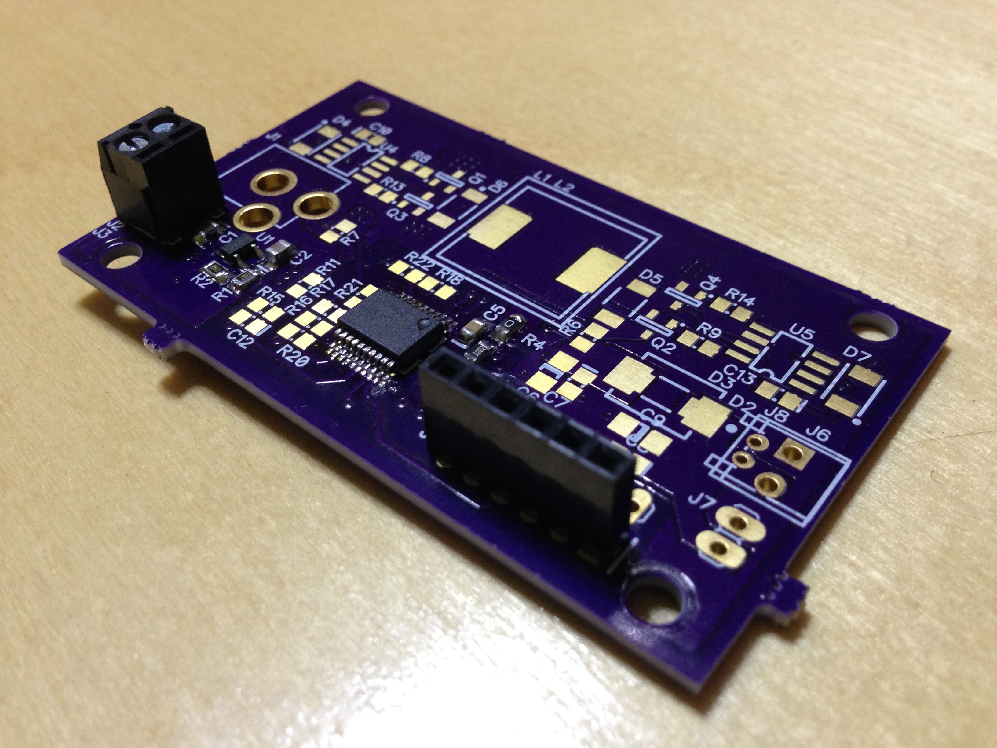
Third, I kept all the components on one side of the PCB. The idea was to allow the PCB to be directly mounted to a solar panel. Some panels offered by Sparkfun and Adafruit have really short leads coming out of the panel, so I thought why not have the MPPT mount directly on the solar panel?
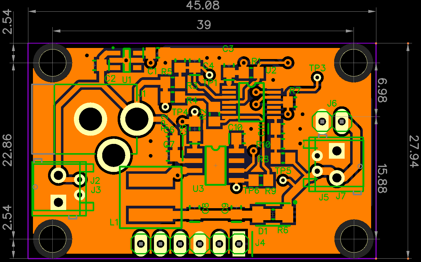
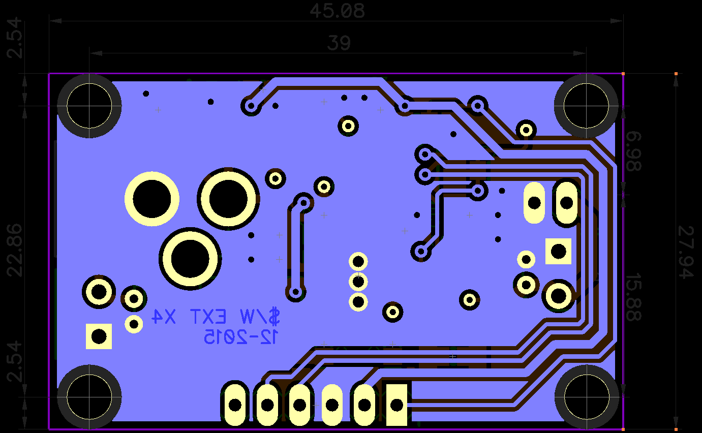
Fourth, I tried my best to get the board layed-out on 2 layers, to save on cost. This project needs to take PCB cost into consideration, so I tried. I'm not happy with the GND plane on both layers: it's cut up pretty bad which reeks to all sorts of havoc. There's some work to get it to my liking.
Here's how layer 1 look like (the big copper pour is GND, and it doesn't look to good):
![]()
And here's layer 2 (somewhat better GND, but that big fat trace in the center of the board makes me quite sad):
![]() Maybe the answer is that this GND setup is a good as it's going to get, or I'll have to pony up and pay for a 4 layer board. We'll see, I need to play with it.
Maybe the answer is that this GND setup is a good as it's going to get, or I'll have to pony up and pay for a 4 layer board. We'll see, I need to play with it.So, with all this said, let's see how much this board truly cost us.
This means that to get a $/W, a 6W+ solar panel would need to be connected to the MPPT board. This isn't terrible, and the boards obviously will work with much lower wattage, but the $/W will go up.
There's a few tweaks that need to happen in order to get this board completely done, but this is a great start. Another spin of the PCB and we should be in great shape.
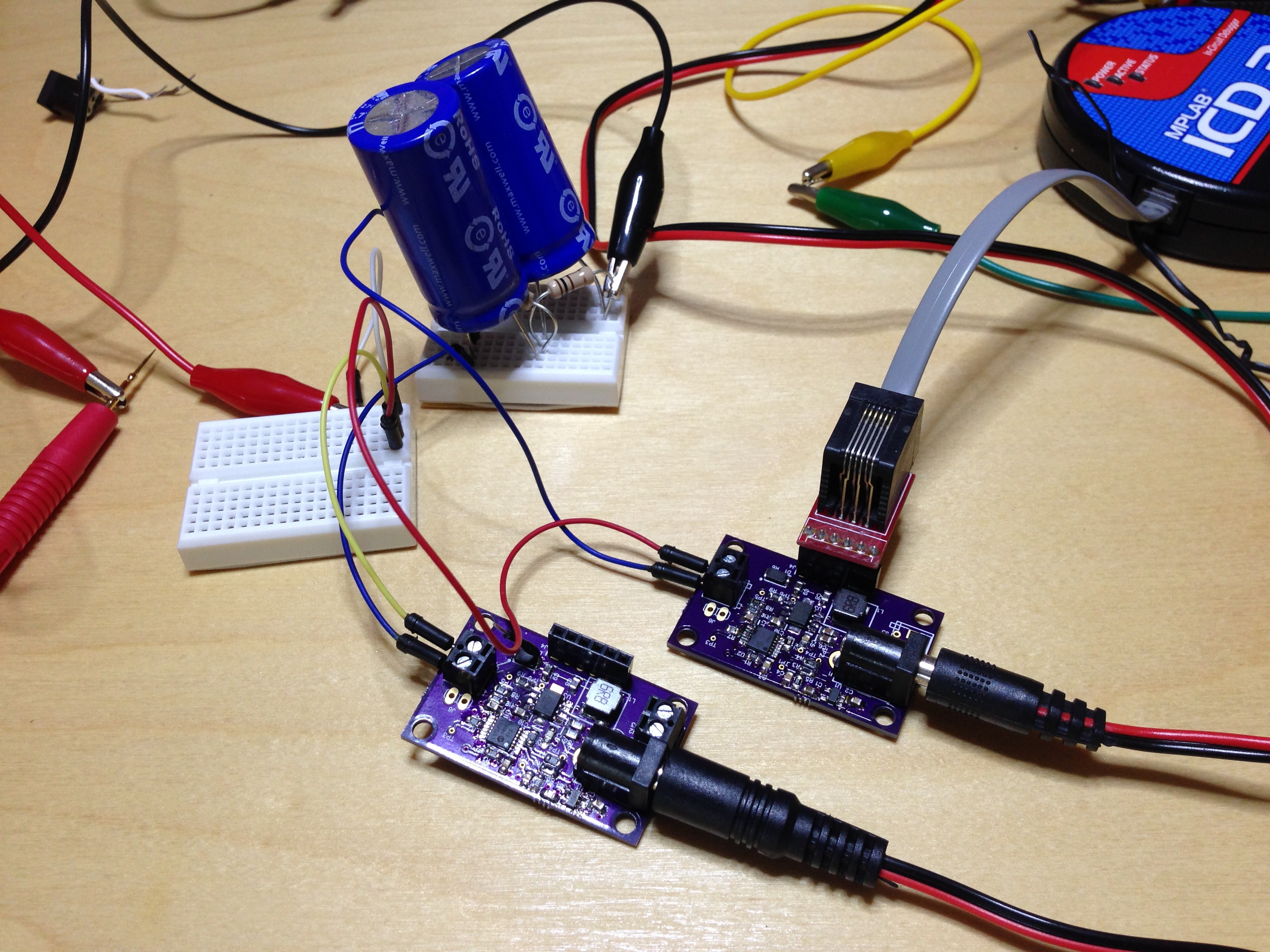
You might be wondering: what's with the diode on the Bill of Materials? Well, did I mention that these MPPT supplies are parallelize-able? Well, they are. Here I have two hooked up in parallel, both changing a super cap bank.
Neat, huh? The power loss through the diode is somewhat negligible at low-ish currents, but the boards has a 0Ohm jumper to bypass the diode if it's not needed.That's it for now. I'll post more news when I get it. Until then, happy MPPT-ing.
-
SEPIC
12/02/2015 at 06:28 • 0 commentsMany moons ago I worked at a company who's quotidian routine included explosions of large capacitors and MOSFETs. During such inevitable mishaps my colleagues and I would meet up around the carnage, and after extinguishing the flames (literally), we would exchange interesting power supply related trivia.
During one such incident we got into the topic of solar MPPT supplies and one of the senior EEs gave a brief mention of SEPICs as a good choice for such use cases. Being young and naive, I quickly dismissed the topology for a variety of reasons (one being that it's hard to control) and never gave it a second thought.
Fast forward to today.
I am please to announce the latest MPPT power supply design fresh off the press: the SEPIC MPPT.
Front:
![]()
And back (with a lot more probes attached):
![]()
I have the supply up and running, and it's working well. There are a few things that need to chance, but I'm getting ahead of myself.
I've been eyeing the SEPIC for quite some time but never got around to actually building one mainly due to the cost of the coupled inductor (or 2 separate inductors) needed for the supply to function. But upon further inspection, the SEPIC offers many advantages over the other typologies.
- The SEPIC is a buck-boost topology.
- The buck-boost is non-inverting (unlike the Cuk).
- Unlike the buck and inverted buck-boost, this topology uses a low-side switch, which makes it easy to drive.
- Currents travel through the low-side switch only when it is closed, which makes for easy current sensing.
- Unlike the boost, no current is transferred to the output until the low-side switch is first closed.
So the trick was trying to find a coupled inductor with a sufficiently low cost to warrant a build. These are hard to find, especially when trying to keep the DC resistance (DCR) down to something that wouldn't ruin the efficiency of the regulator. These matters are made worst by the fact that I have to switch at a rather low frequency (sub-MHz), thus requiring a larger inductor. Some math pointed me to 47uH per coil, which made things tricky.
After a long search, I landed on Coilcraft's MSD1278 coupled inductor series. At $0.76 @ 1000 with a DCR of 0.18 ohms, these ain't cheap, but they strike a good balance of efficiency vs. cost. I found some cheaper alternatives, but their DCRs were significantly larger (sometimes a whole order of magnitude larger).
With coupled inductor in hand, I was ready to draw a schematic.
![]()
This is the same schematic as shown on the wikipedia page, but drawn slightly differently to group the coupled inductor into a single schematic symbol.
You can see the low side current sense resistor R15, which feeds into an Non-Inverting OpAmp. R10/R14 form the output voltage sense, and R12 is the current limiting resistor to the MOSFET gate.
Something worth noting here. Since the coupled inductor cost more than I wanted, I felt the need to reduce cost somewhere else. The current MCU I'm using (PIC16F1704) can output 25mA/port, with a grand total of 170mA for the whole part. This isn't a whole lot, but if the gate of the MOSFET is sufficiently small, could be enough to directly tie 4 pins directly to the MOSFET and remove the drive altogether.
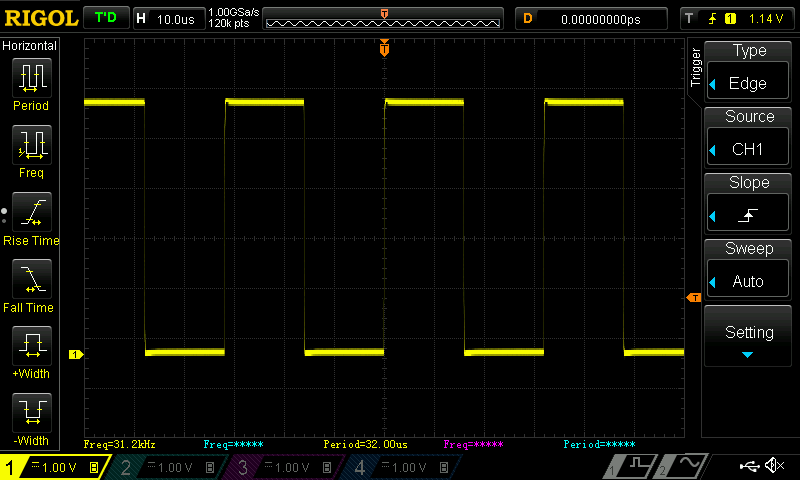
This was a gamble, but I was willing to take it. So I replaced R12 with a 50ohm resistor and took some measurements.
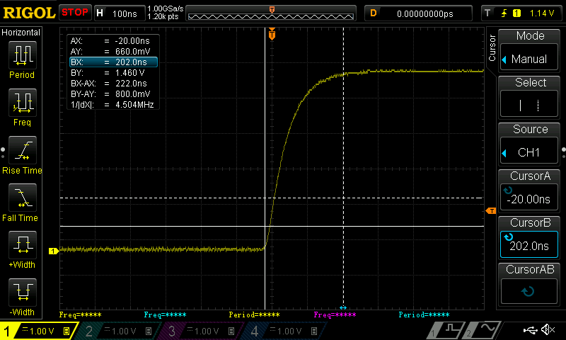
At 31kHz, the signal looks quite good:
![]()
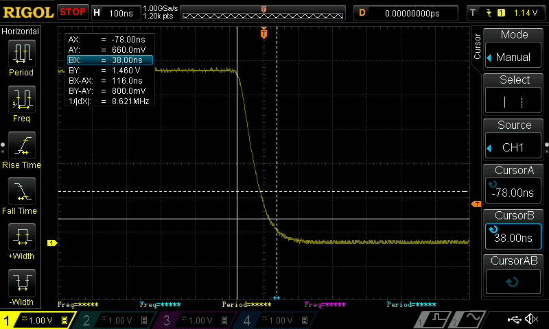
Upon close inspection you can see the rise and fall time.
Rise time plot:
![]()
Fall time plot:
Judging from these plots below, it looks like I shouldn't switch faster than 2MHz. For fun, I decided to test this out.![]()
![]() That does *not* look like a square wave...
That does *not* look like a square wave...These results are encouraging, as removing the MOSFET driver saves $0.25 @ 1000, amortizing the coupled-inductor costs quite well.
So mission accomplished, right? Well...
There's one catch to this current design. In order to get the desired switching frequency (160kHz-ish), I have to significantly reduce the resolution of the PWM generated by the PIC16. This gives me a rather large PWM duty cycle step size: large enough that the solar panel voltage changes by 0.4V per step, which is quite huge. The large jumps in voltage for a small change in duty cycle makes the tracking of the MPP hard to maintain, and I had to significantly dampen the controls in order to achieve acceptable results.
This is not ideal as it would not track the MPP well in variable outdoor conditions. I could increase the coupled inductor size and reduce the switching frequency to achieve a higher PWM resolution, but this increase the cost of final design as well as reduces the efficiency.
A potential solution would be to switch to the new PIC16F1764, which offers a highly superior PWM peripheral that addresses my issue, but at a $0.40 rise in cost.
I have to percolate this over some. As always, suggestions are welcome.
-
The RT8299 Proper Hack
10/29/2015 at 01:35 • 1 commentIn a previous project log, I did a first stab attempt at hacking the RT8299 to perform MPPT by running a PWM on the enable pin. This failed miserably.
The next obvious hack was to have the feedback pin (FB) of the RT8299 tied to the solar input. In this way, the RT8299 would regulate the solar panel's voltage (instead of the output of the regulator), in effect doing MPPT. This is easy, and there are other people who have already done this, but the trick in doing this right is to have the MCU still control and update the tracking point as time goes by (in function of temperature, irradiance, etc.), and doing so with the least number of parts.
The easy solution is to use a digital potentiometer to update the tracking point, but they don't go for super cheap. I really didn't want to add a digital potentiometer.
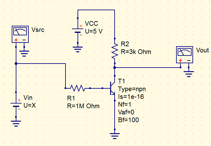
I was kind of stumped, until yesterday. MCUs come with a DAC, which is a form of a potentiometer packaged slightly differently. With a small tweak to the schematic, I could get the DAC to behave similarly to changing a potentiometer. My first draft at this came in the form of this simple circuit:
![]()
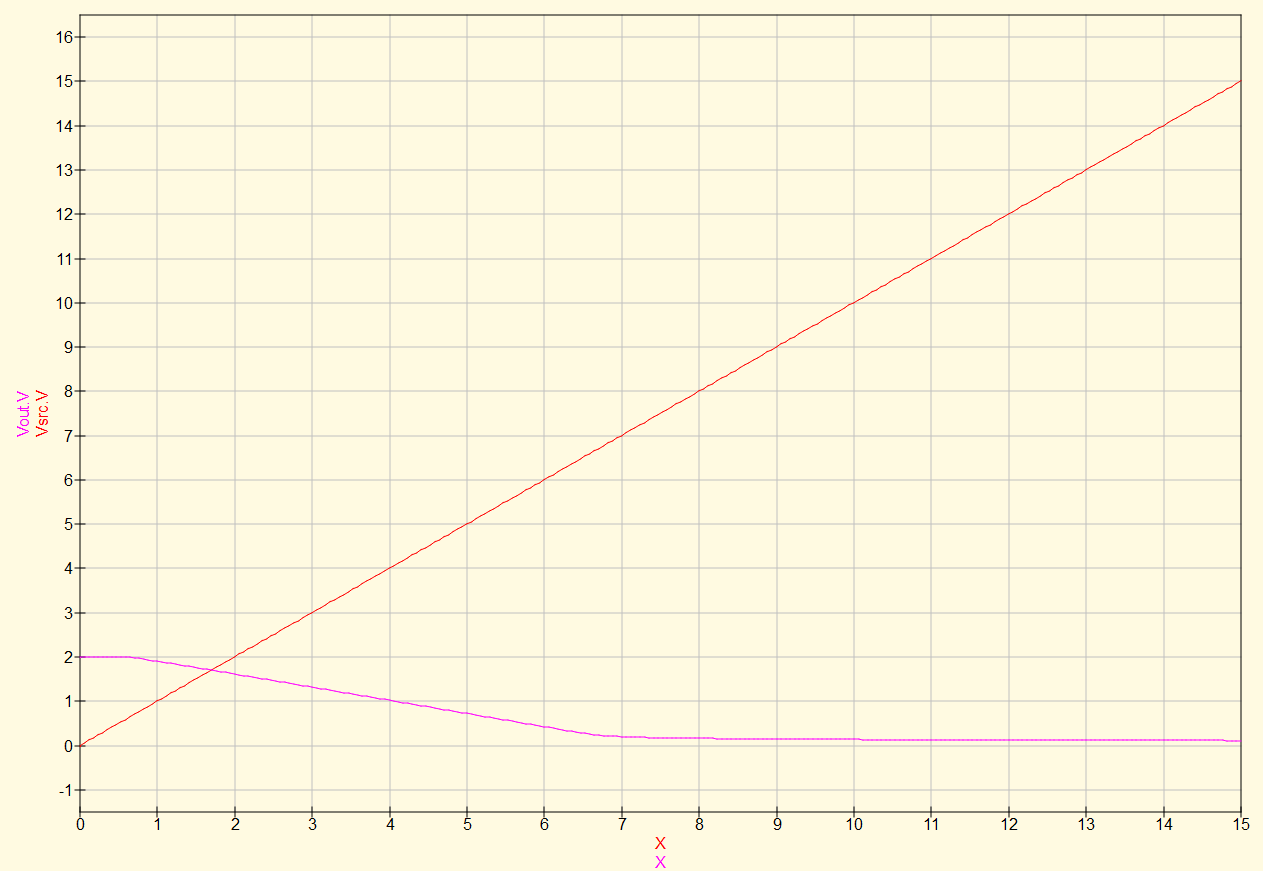
Here, Vsrc is the solar panel, Vout is the output that ties to the FB pin of the RT8299, and VCC is the supply powering the MCU. The idea is that as the voltage on the panel rises, the NPN BJT pulls an increasing amount of current, which in turn, lowers the voltage seen at Vout. Since the RT8299 regulates the FB pin to 1V, the panel will be allowed to rise in voltage until a certain voltage when Vout = 1V, which in effect, performs the MPPT.
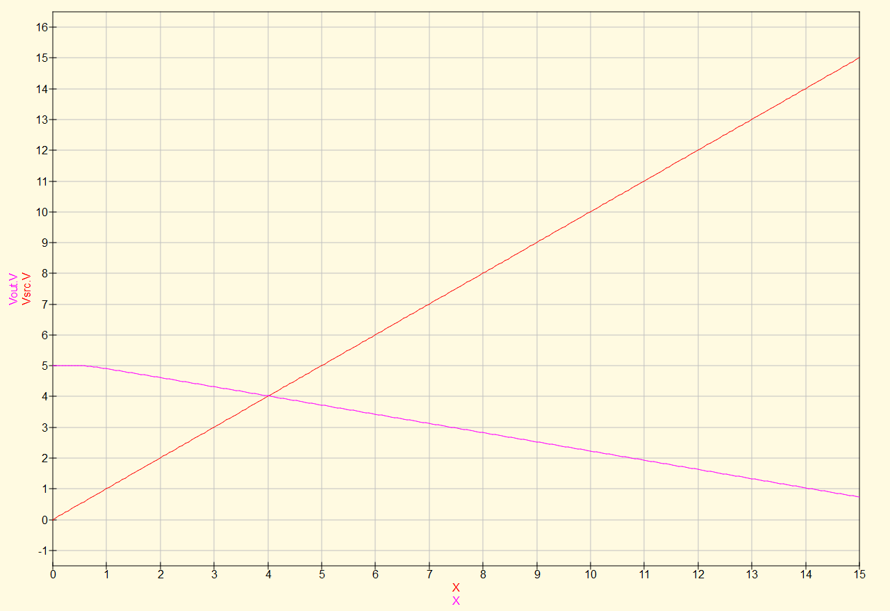
I ran a simulation for the circuit above, and this worked out splendidly.
![]()
Looking at this plot, the RT8299 would keep the solar panel voltage right around 14V, which is the point upon which Vout = 1V.
Ok, so with this in mind, imagine I change VDD to, say, 2V. The voltage seen at Vout will maintain the same slope as before since the transistor will pull the same amount of current as before since it's controlled independently from the VDD voltage. On the flip side, the lower VDD voltage will start the graph (Vsrc = 0) at a lower point.
![]()
So now, the RT8299 would regulate the solar voltage to 4V. Replace VDD with the output of a DAC, and now we can control the set-point for the MPPT. Great!
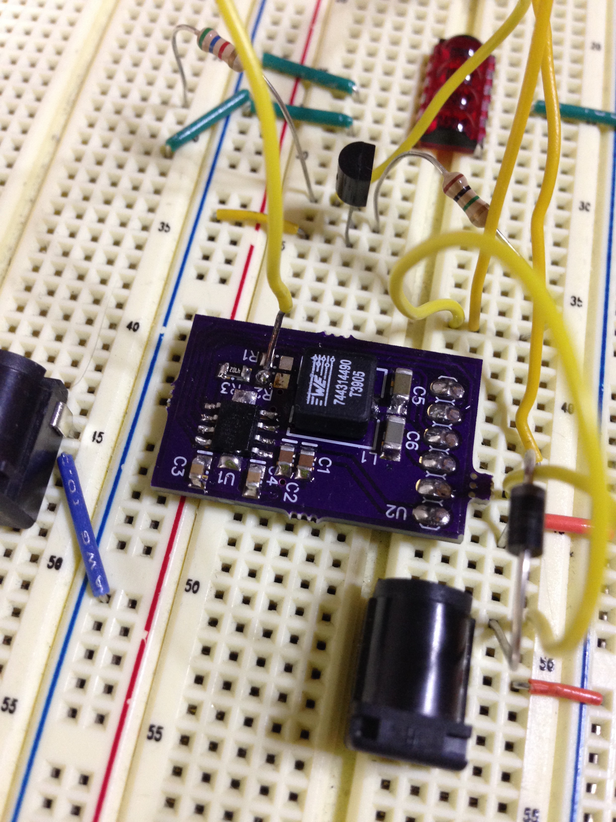
I breadboarded this, and it worked! I used a 2N2222 NPN BJT and added a wire to the RT8299 breakout board to override the FB pin. The DAC voltage came from an MCU running a simple 80% VOC MPPT algorithm.
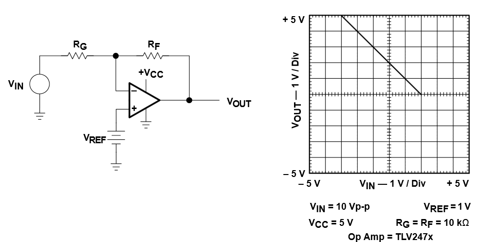
I did have to add a unity gain amplifier to the output of the DAC to get this circuit to properly behave, and so since I need an amplifier, I dispensed of this NPN BJT craziness went with a single supply inverting OpAmp.
![]()
In the OpAmp circuit above, Vref is driven by the DAC output, giving the same net effect.
[BTW, I got this schematic from TI's amazing OpAmp circuit collection, which I highly encourage you grab yourself a copy (after all, it is free).]
So now the question is: how much do I care for the Buck-Boost functionality? I've looked to see if I could find a buck-boost IC for the same price as the RT8299, but no go. The advantage of the Buck-Boost is that panels of lower voltage can contribute to a higher voltage load: think 6V solar panel charging a 12V battery. On the flip side, this buck-only solution is really cheap.
I've even tried to look to find a boost converter which I could turn into a SEPIC, but the coupled/dual-inductor requirement of the SEPIC increases the cost. And forget about building a Buck-Boost out of discretes: it's more expensive than building a SEPIC.
Guess you can't have your cake and eat it too.
-
A Small Mistake Goes a Long Way
09/25/2015 at 05:15 • 0 commentsI got the PCBs back and started soldering. The power rails (LDO + Charge Pump) and connection to the MCU seems to be working just fine.
All seemed to be going well until I reached the point where I wanted to add in the makeshift current sensor. I used the schematic below to implement the high-side current sensors (as shown in this AppNote).
![]()
But there's a catch. If you look closely at the equation, you'll notice that in order to get a positive gain, R2 must be greater than R1. In making R2 always greater than R1, the circuit above guarantees that the voltage input going into the OpAmp will be greater than the supply powering the OpAmp proper (in this case, VDD) for sense voltages greater than VDD. If this boards was simply a buck converter, this wouldn't be a problem, but since this is a buck/boost converter, we most definitely run in this issue.
What I needed to do was set up a voltage divider that made the voltage stay within the 0-VDD limits and THEN setup a difference gain amplifier. And so this PCB has no current sensors neither on the input (which is almost always above VDD) nor the output when Vout > VDD. Great.
This led me down a slippery slope. The cost of my current solution is within budget but high considering ICs already implement buck/boost functionality at a fraction of the cost (without MPPT control), a large chunk attributed to the smaller inductors made possible by higher switching frequencies and the high level of integration offered by the IC. So I started looking at ways to reduce the BOM count.
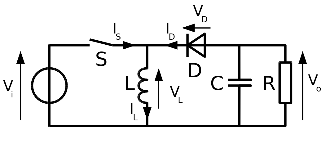
In comes the inverting buck-boost regulators.
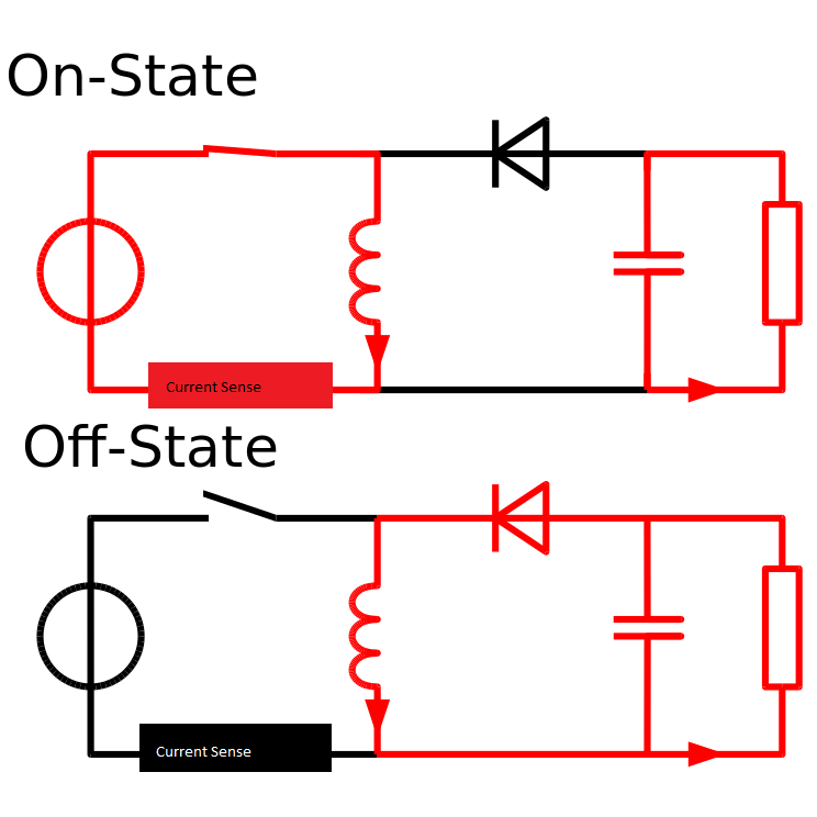
It only needs one switch, an inductor, diode, and output capacitor to make it work, and for that, it's brilliant. This design is made more awesome by the fact that a low-side current sensor can be used between the inductor and the Vi source, as that path is only enabled when the switch is closed.
![]()
The trick here is to make the high-side switch work. If I play my cards right, I could get rid of the charge pump on the current design (needed to get the voltage up high-enough to drive the NFETs), driving down costs even further. The trick with high side switches is that there are no simple solution, just a series of compromises.
I welcome suggestions/feedback, especially with regards to a high-side switch driver. All I'm seeing thus far doesn't go below 5V, and my target is 2.5V to 18V.
-
First Stabs at the RT8299 Hack
09/10/2015 at 05:53 • 1 commentIn a previous project log I talked about using the RT8299 buck regulator and PWMing the enable pin to simulate a MPPT. While this isn't necessarily a textbook MPPT solution, it is an appealing one due to the high level of integration and low cost offered by the RT8299.
So I sent out a breakout board and stuffed it. Here it is, in all it's glory:
![]()
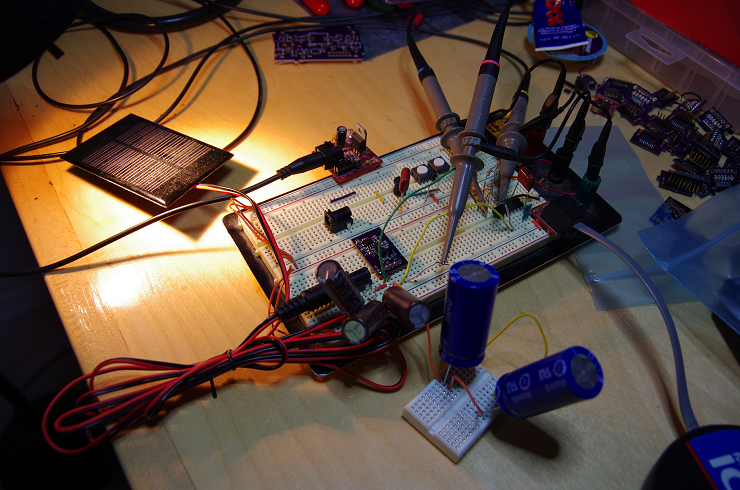
This little guy was the wired to a breadboard and then to the PWM pin of a PIC16F1705 I had handy. The input solar panel was a 5V panel lit by a lamp (playing at night requires such awful hacks) and the output of the regulator was tied to 400F 2.7V supercapacitors (nope, I didn't typo here: 400F). The extremely large capacitance acts as a giant charge sink, eliminating the effects of the output voltage on the input voltage, thus allowing me to concentrate on the input response (i.e. the MPPT portion). The proper solution this this would be to use a electronic load bank, but since I'm lacking the cash to get one, these caps will do. Here's what the whole setup looked like.
![]()
The idea of operation was simple: stop the PWM to find out the open circuit voltage of the solar panel, multiply this value by 0.8 (the MPP), and control the solar panel voltage to this point by changing the pulse width of the PWM. 100 lines of code got me there.
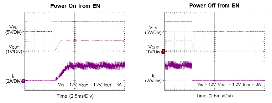
But before I can run an MPPT, I need to understand the step response of the RT8299 when the regulator goes from the off to the on state, and vice versa. The results were rather surprising.
Since the part has a soft-start period of 2ms, I setup the PWM period to run just around that point s.t. we never let the regulator go to full on. Doing so would drag the solar panel voltage all the way down to the undervoltage lockout (UVLO) threshold of the RT8299, nullifying all MPPT benefits.
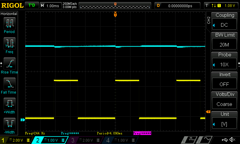
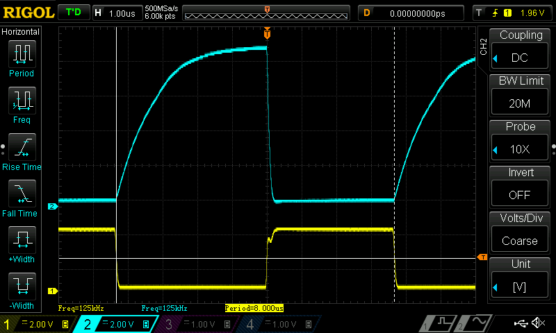
Below is a capture of the solar panel voltage (blue) in response to an on/off PWM duty cycle (yellow) of slightly less than 50%, making sure that the on time was less than 2ms.
![]()
Normally I would expect the solar panel voltage to go down some as the regulator begins to energize the inductor, but it doesn't really budge. Knowing that the soft-start was 2ms, I changed the duty cycle to something slightly above 2ms.
![]()
Oh my. Well, once the soft-start period is over, the regulator goes fully on as expected and drags the voltage all the way to the UVLO. So much for a soft-start. I was expecting a smooth ramp-down in solar panel voltage in the time between the enable pin goes high and the soft-start period ends. This doesn't mesh well with the datasheet, which shows a smooth current ramp-up.
![]()
It seems as if the soft-start relies on the rise in output voltage to properly operate. If so, having those 400F capacitors would explain why the soft-start isn't working well.
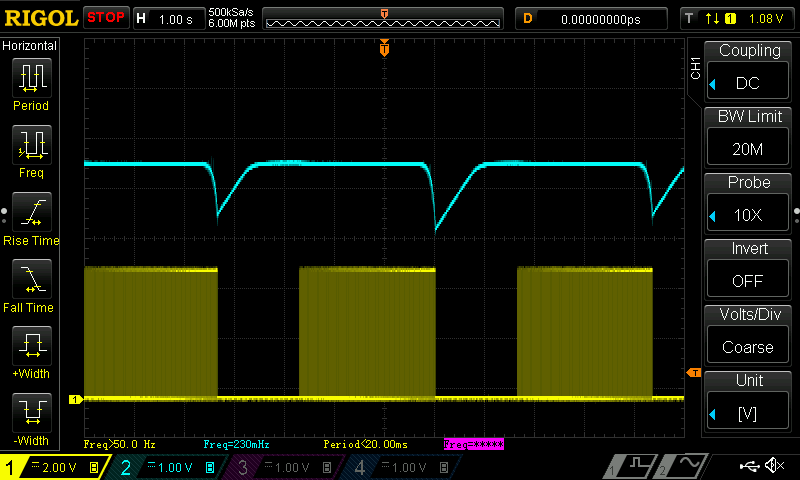
I then decided to add a lot (1mF) of input capacitance on the solar panel to try and hold up the voltage long enough to better understand the soft-start behavior. While it helped a little, the sharp drop in voltage was still fast and sudden. For fun, I turned on the MPPT control loop to see what would happen, and the loop gives up once the softstart period ends and suddenly brings the solar panel voltage all the way to the UVLO. The plot below shows the control loop gradually increasing the PWM duty cycle until the voltage drops, at which point the loop gives up and tries again (waiting for the solar panel voltage to stabilize at it's no-load voltage).
![]()
There's still hope of making this work, but for now I'm out of idea, so I'll temporarily put the RT8299 to rest and start working on the V2 power supply, which I've recently received the PCBs. Ideas or suggestions are welcomed.
-
Progress
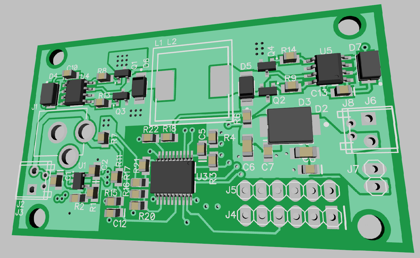
08/23/2015 at 05:31 • 1 commentSmall update to show you the layout for the V2 board. I changed the topology to be a Buck/Boost converter, as I'm not entirely sure which one I'd like to use. While the buck converter works just fine, it would fail to allow lower voltage higher-current solar panels to charge higher voltage sources, such as a 12V battery. This new version also has input and output over-current protection, which eliminates the need for the fuse which would blow too slowly anyways.
As long as the supply can output 5W as designed, we're looking at approximately $0.46/W.
At any rate, here's what the board currently looks like (some of the 3D models are missing).
![]()
-
Two Options
08/05/2015 at 05:16 • 1 commentOver the last few weeks I've been searching the web trying to find the right balance of parts and cost in order to meet or exceed the $1/W budget. I've compiled a long list of possible configurations in an Excel sheet (see sample below) and have narrowed it down to two options.
![]()
But first, allow me to tie up some loose ends.
Originally I had thought that driving a P-Channel MOSFET (PMOS) on the high side would help reduce on cost. While this is true, the cost difference between using a PMOS vs. an NMOS is only about $0.06/W. That is to say, having a half-bridge driver + NMOS is just slightly more expensive than using a PMOS with respective circuitry to drive it. This is true because driving a PMOS isn't as simple as doing something like this:
![]()
Image taken from Maxim's App Note 1158.
The reason this doesn't work is because the PMOS' gate has some capacitance associated with it, and so when the lower NMOS turns off, an RC circuit is formed between the pull-up resistor and the PMOS gate capacitance. In effect, this causes the PMOS to turn off slowly for large resistances and/or gate capacitances. Below is a capture I did of a PMOS of interest driven in this manner:
![]()
The yellow line is the NMOS gate input, and the blue (cyan?) line is the PMOS' gate. That long rise time on the blue line is the problem. The PMOS quickly turns on, but turns off rather slowly, which causes shoot through problem in synchronously rectified buck regulators, in turn affecting the regulator's efficiency.
I was able to get the PMOS to turn off quickly, but the resistor value needed to accomplish this was unacceptably large, thus voiding this simple circuit for synchronous buck regulator.
Of course, it is possible to drive a PMOS quickly using a more involved circuit, but for the same price I can get an integrated NMOS half-bridge driver. The one I'm currently eyeing is the NCP3420, and at $0.24/1000 parts, that's nothing to scoff at. Pair that with two DMN3404L-7 NMOS, and we're looking at a total BOM of $1.64 (includes microcontroller, current sensor, passives, etc.).
The half-bridge driver runs on 5V, so if we want our MPPT regulator to support 5V solar panels, then we need to add a charge pump to bring-up the voltage to 5V when the solar panel's voltage is lower. The cheapest reasonable regulator I could find was the MAX1720, bringing the new total to $1.88.
This is pretty good, and I'm currently layout out the board for this option.
There is, however, a possible second option. mr.jb.swe suggested using a buck regulator IC and tying the enable pin to a PWM coming from a microcontroller (MCU). In other words, instead of having a MCU drive a MOSFET driver IC, the MCU would drive the enable pin of a "all in one" ready made buck regulator. There are several advantages to using this method.
- It's considerably cheaper. For instance, using the RT8299 runs me at $0.33/1000 parts and would bring the BOM down to $1.53, or a savings of $0.35.
- It includes the half-bridge driver, the bootstrap diode for the driver, the NMOS fets, and a high-side current sensor with over-current protection.
- Being integrated, using this part would make the PCB smaller, which lowers PCB costs.
- Since all the work is done by the external buck regulator, the requirements for the MCU running the MPPT algorithm is substantially lowered. All the MCU needs to do is read an ADC channel and generated a PWM output. No comparators nor fancy PWM are needed, and the MCU can be clocked at a much lower frequency.
- The integrated regulator has over-temperature limits included, which eliminates the need for the MCU to do this work.
The one catch to this option is that there are start-up costs associated with each off/on cycle of the enable pin on the external buck regulator. That being said, I *HAVE* to try this option, as it is by far the most cost effective solution and I'd be crazy not to give this a whirl. Who knows: perhaps the savings will outweigh the start-up cost.
More to come.
-
Current Sensor Musing
07/05/2015 at 03:30 • 2 commentsLately I've been looking for the right current sensor, or said differently, the best bang for the buck, while staying in budget. Taking into account the other components on the PCB, I figure I have around $1 to budget. I also prefer high side current sensors as they eliminate the possibility of accidentally tying the PVs GND to the output's GND, which would bypass a low-side current sensor.
High-side current sensors come in two flavors: those with an external VDD pin, and those who use the sensor input (common-mode voltage) to power the IC. The latter tend to be less costly but require a minimum common-mode voltage in order to properly operate. This means that said current sensor could not be tied to the output of the buck regulator since at lower voltages the sensor would not work (imagine charging a supercap at 0V). These sensors would need to be tied to the solar input. The two common-mode current sensors I'm currently eyeing are the TSM9938 and the TS1103.
On the pricier end, the MAX4428 is powered using a dedicated VDD pin. This sensor gives much better results and could be placed on the output of the regulator, but again, it cost more.
And so I'm in a pickle. I could either place a single high-side current sensor on the input or at the output, but not both, as I go over budget.
Having the current sensor on the input has certain advantages: I can easily track the actual MPP as I would have both the input voltage and current for the PV proper. However, this configuration prevents me from measuring the current on the output. I could play a game where I calculate the output current in function of the output voltage and assume that the power supply is 100% efficient (to be conservative), but doing so is unreliable (actual output current reading is still unknown) and the over current protection may be too slow to respond (could only respond as fast as I could run the control loop).
Conversely, having the current sensor on the buck regulator's output gives me an accurate over current protection but an inaccurate actual PV current. I could get away with estimating the PV's current assuming 100% efficiency, but this is not ideal for the same reasons listen above.
Maybe I'm causing myself entirely too many headaches. Maybe the real answer is placing a low-side current sensor (cheap) and somehow emphasize that the PV's GND should not be tied to the output's GND.
As usual, I welcome suggestions.
$1/W True MPPT
Build a $1 per Watt parallelizable MPPT controller, without cutting corners.
 Jonathan Bruneau

 Maybe the answer is that this GND setup is a good as it's going to get, or I'll have to pony up and pay for a 4 layer board. We'll see, I need to play with it.