 PK
PKThe User Guide in the last entry has an order of operations to build VGATonic. This article is more of an overview and a look at how to program the firmware for the CPLD and the microcontroller.
This guide is for Rev_A of the board (link is to GitHub) - so named in case there are more VGATonics in the future!
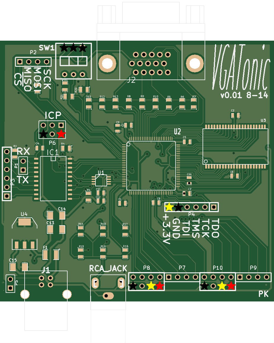
Here is a blown up board, with power and ground marked (Black - Ground, Red - +5V, Yellow - + 3.3v).
Parts Selection
Cost is about $20.50, plus shipping - you can (of course) do cheaper depending on where you source the parts or how many you buy.
I have a BOM here, and I have the parts guide here on Github with exact part numbers and tolerances. You can substitute close values - but for the output stages, use the same value and tolerance resistors - it's best to use 1% or less for the output stage. Everything else is just fine with 5% tolerance.
Ease of Building
If you can get past soldering the CPLD, it's not a hard board to assemble. The 0603 decoupling capacitors are annoying, but surface tension generally pulls them onto their pad.
Those 2 steps probably take half your soldering time! (You can do it though - the CPLD was the smallest pitch part I'd ever soldered and I managed to get 6 working boards, haha.)
I suggest using solder paste and investing in one of those flux pens - and have a fair amount of desoldering braid on hand for solder bridges on the parts.
The CPLD
If you don't want to fire up ISE Webpack yourself, here is the firmware I am currently using. That package contains the .jed file and an .xsvf file - the XSVF can be programmed with something like a Bus Pirate.
Otherwise, the VHDL can be found here.
The Microcontroller
The microcontroller is trickier - it has a calibration step so I can't really post Arduino files; luckily the IDE is easy to use!
You can find the EEPROM and the standard firmware here.
It's a two, maybe three step process since we are using that internal oscillator. Start with Arduino Tiny Core's 1.5 version. I'm using 1.6.5 of the IDE - you need to use at least 1.6.2 to get the EEPROM functions. Next, comment out the Hardware Serial files - we will be managing UART directly. (Editor: you can find my commented out files on Github as detailed in this project log)
If any of these steps are confusing let me know, I'll add details and perhaps some code samples:
- (Optional) Calibrate the "OSCAL" register. I'm using Jason Pepas's method of sending 'U's over UART - use whatever is most convenient.
- Burn the EEPROM version of the VGATonic Firmware. All you need to do is uncomment the line //#define EEPROM_UPDATE 1 in the main .ino file.
- (Optional) If you calibrated VGATonic, change the calibration bit in "utilities.ino".
The line looks something like this: eeprom_update_byte (( uint8_t *) OSCALSPEED, 'O' ); (Change the 'O' to your value).
- (Optional) If you calibrated VGATonic, change the calibration bit in "utilities.ino".
- Burn the normal VGATonic firmware - just recomment the line #define EEPROM_UPDATE 1
Discussions
Become a Hackaday.io Member
Create an account to leave a comment. Already have an account? Log In.