PK
PK-
Videos and Some Older Material!
08/17/2015 at 05:31 • 0 commentsIf you've been following along, you've probably seen my Quarterfinals Video and Semifinals Video already:
- Semifinals (~ 5 Minutes)
- Quarterfinals (~ 2 Minutes)
One of the requirements of the Best Product category is to show some videos of the prototype in action. I have some linked on the sidebar, but I wanted to link some here to make them easier to find:
- The Intel Edison was a nice addition to the framebuffer code; it started headless but I got it to play Quake at 40 FPS. I wrote up another project log if you're interested in reproducing the work!
- Here is this year's kickoff video, Doom on a Raspberry Pi.
- Last year, after the PCBs came in, I got a version running on the Intel Galileo running in "Arduino mode". Here are some early signs of VGATonic life.
- A very early prototype using a CPLD breakout with no SRAM - but doing NTSC and VGA from the same clock source!
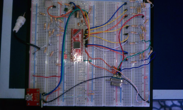
It's fun to reflect on how far this project has come! Here's where it all started, on a 4 row breadboard (complete with painstakingly placed R-2R resistor ladders!):
![https://cdn.hackaday.io/images/8853771407209727512.png]()
Good luck to everyone contending with the 2015 Hackaday Prize deadline!
-
Arduino Uno Driver, Hardware Acceleration Example
08/16/2015 at 19:24 • 0 commentsI just pushed some Arduino Uno driver code to the Github Repository showing how to skip to individual lines. You can find it in the User Driver directory, and I called it "SPI_test". Just hook up VGATonic SCK, MOSI, and CS to pins 13, 11, and 9, respectively, on the Uno, then power it up!
If all goes well, you should see the pattern covered at around 1:19 in my prototype video now running on your VGATonic:
That's the third and the arguably the most subtle of the hardware acceleration methods on VGATonic, but is very useful for slow parts. Take the 2 MHz SPI from the example code - normally, that can push under one frame per second at 640x480x8 bit color (which requires roughly 2.5 million bits per total screen)... but by skipping to specific lines it creates the illusion that VGATonic is actually writing from bottom to top!
I forsee this being most useful for GUI development on slow serial parts - imagine having a constantly refreshing menubar on the bottom of the screen, but not needing to refresh the entire screen content if only the menubar changes. It's also useful for something like a mouse cursor, where only some of the screen needs a redraw and blasting the entire screen is a waste of resources.
Here are all three forms of acceleration onboard:
- Resolution and Bit Depth Changes - the bread and butter of the video card; reducing bit depth and/or resolution requires less serial bytes per screen refresh. Ranges from 640x480 @ 8 bit (2,457,600 bits) down to 80x60 @ 1 bit (4,800 bits).
- Chip Select Toggling - toggling chip select without any additional commands will reset the writing position to the upper left column and row, regardless of where it was previously positioned. This means a device can write an arbitrary number of pixels (assuming at least 2 bytes are sent; 1 byte is a special control character, detailed in the User Guide), and doesn't need to write until the last pixel in the lower right.
- Hardware Accelerated Positioning - detailed in this article and in the example code, this lets a device skip to individual rows for writing instead of starting from the upper right hand corner. For 640x480, this allows skipping 8 rows at a time (320x240 4, 160x120 2, and 80x60 1), vastly increasing throughput for slower parts.
-
System Design Document
08/16/2015 at 09:21 • 0 commentsI just finished the initial System Design Document. It also includes some newly measured details on power consumption (Edit: I set up a better test bench with a reliable adapter today; picture/results below).
It also lays out some of the future work I'd like to complete, including additional firmware - so folks who don't want to use VGA can switch to NTSC or something instead.
This document is on top of the User's Guide I released (with the Hacker's Guide inset!) that lists a lot of the features onboard, and details some of the protocols I used. If you're interested in VGATonic, I'd suggest reading them both!
Update:
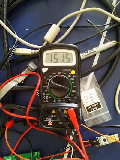
I set up a better testbench today. Here is a picture of one of the worst case readings:
![]()
I'm getting between 140 and 158 mA @ 5V here, so let's call it between .7 and .85 Watts for a graphics card. Not bad - I'd say that competes pretty well with what's out there, haha!
-
Minor License Updates - Third Parties
08/14/2015 at 15:15 • 0 commentsI made very small modifications to the arduino-tiny core, specifically 4 lines of preprocessor directives to disable code. I am commenting out code in both HardwareSerial.cpp and HardwareSerial.h in order to have VGATonic handle the UART interrupts on its own (this is the relevant code block that interferes):
ISR(USART_RX_vect)
{
  uint8_t tmp = UDR;
  if (rxn==BUFFER_SIZE)
    rxn=0;
  RX_BUFF[rxn++] = tmp;
  rx_flag=1;
}
A strict reading of license terms counts disabling code as a modification, so I wanted to document that arduino-tiny is licensed under LPGL. I have released my modifications to arduino-tiny on Github here.
You can directly overwrite the arduino-tiny files when installing arduino-tiny core, but on a Mac they go here (Arduino IDE 1.6.5):Arduino (Right Click) -> Show package contents
/Contents/Resources/Java/hardware/tiny/avr/cores/tiny/ -
Brief Update, Added UART Framebuffer Code
08/12/2015 at 15:56 • 0 commentsDue to a well timed suggestion from @antti.lukats in chat, I went through and made the licenses more explicit today. Basically everything is MIT licensed, except code which derives (or is used in) the Linux Kernel - all of that is, of course, GPL v2.
I'm not sure if anyone has built a VGATonic yet, but today's update includes the Python code I've been using to test the serial framebuffer driver. The libraries you need are pyserial and Pillow. You can pick either 9600 or 38400 baud, and it will blast images over UART to VGATonic. (Set the image with the -i command). Here're some examples:
python SerialDemo.py -x 640 -y 480 -c 8 -d 0 -i VGATonic.png -v 2
python SerialDemo.py -x 640 -y 480 -c 4 -d 1 -i ground.jpg -v 2
python SerialDemo.py -x 320 -y 240 -c 4 -d 1 -i edison.png -v 2Here are some command line options:
# -d Controls dithering - 0 off, 1 on (Default off - but for that 90s vibe, try some with it on!)
# -c Controls color depth, 8, 4, 2, 1 all legal
# -x Controls width, 640, 320, 160, 80 all available
# -y Controls height, 480, 240, 120, 60 all available (has to match width - so 640x480, 320x240, 160x120, 80x60)
# -m Movie mode - probably just stick to 80x60x1 bit or x2 bit, but this mode rotates the image "-m" times.
# -i Controls the file to input (there are some images in the directory to try)
# -p Change the port - default is in code
# -b Baudrate. Pick 9600 or 38400
# -v Verbosity, set to an integer. '2' is the highest level, it'll give you some stats too.On the driver side, I made a BBB update as well:
- The BeagleBone Black board specific driver file was updated to ask for 19.25 FPS in 640x480x8bpp - it looks pretty good!
As always, find all the most recent code here on Github: https://github.com/dqydj/VGAtonic
-
Longer VGATonic Overview Video
08/11/2015 at 15:57 • 0 commentsHey folks, I stayed up late last night and finished the five minute VGATonic overview:
Showing a lot of new stuff here, but here are some highlights:
- Multiple monitors (3 screens on an Odroid C1)
- Also show some of the VT52 escape codes in that clip
- Every bit depth and resolution accelerated by VGATonic on Linux (LXDE)
- Video of the BeagleBone Black in action at 640x480 and 320x240 in 8 bit color
Hope you enjoy it!
- Multiple monitors (3 screens on an Odroid C1)
-
Build/Programming Details
08/09/2015 at 18:59 • 0 commentsThe User Guide in the last entry has an order of operations to build VGATonic. This article is more of an overview and a look at how to program the firmware for the CPLD and the microcontroller.
This guide is for Rev_A of the board (link is to GitHub) - so named in case there are more VGATonics in the future!
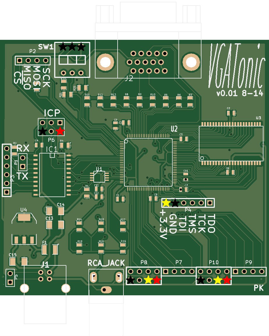
Here is a blown up board, with power and ground marked (Black - Ground, Red - +5V, Yellow - + 3.3v).
![]()
Parts Selection
Cost is about $20.50, plus shipping - you can (of course) do cheaper depending on where you source the parts or how many you buy.
I have a BOM here, and I have the parts guide here on Github with exact part numbers and tolerances. You can substitute close values - but for the output stages, use the same value and tolerance resistors - it's best to use 1% or less for the output stage. Everything else is just fine with 5% tolerance.
Ease of Building
If you can get past soldering the CPLD, it's not a hard board to assemble. The 0603 decoupling capacitors are annoying, but surface tension generally pulls them onto their pad.
Those 2 steps probably take half your soldering time! (You can do it though - the CPLD was the smallest pitch part I'd ever soldered and I managed to get 6 working boards, haha.)
I suggest using solder paste and investing in one of those flux pens - and have a fair amount of desoldering braid on hand for solder bridges on the parts.
The CPLD
If you don't want to fire up ISE Webpack yourself, here is the firmware I am currently using. That package contains the .jed file and an .xsvf file - the XSVF can be programmed with something like a Bus Pirate.
Otherwise, the VHDL can be found here.
The Microcontroller
The microcontroller is trickier - it has a calibration step so I can't really post Arduino files; luckily the IDE is easy to use!
You can find the EEPROM and the standard firmware here.
It's a two, maybe three step process since we are using that internal oscillator. Start with Arduino Tiny Core's 1.5 version. I'm using 1.6.5 of the IDE - you need to use at least 1.6.2 to get the EEPROM functions. Next, comment out the Hardware Serial files - we will be managing UART directly. (Editor: you can find my commented out files on Github as detailed in this project log)
If any of these steps are confusing let me know, I'll add details and perhaps some code samples:
- (Optional) Calibrate the "OSCAL" register. I'm using Jason Pepas's method of sending 'U's over UART - use whatever is most convenient.
- Burn the EEPROM version of the VGATonic Firmware. All you need to do is uncomment the line //#define EEPROM_UPDATE 1 in the main .ino file.
- (Optional) If you calibrated VGATonic, change the calibration bit in "utilities.ino".
The line looks something like this: eeprom_update_byte (( uint8_t *) OSCALSPEED, 'O' ); (Change the 'O' to your value).
- (Optional) If you calibrated VGATonic, change the calibration bit in "utilities.ino".
- Burn the normal VGATonic firmware - just recomment the line #define EEPROM_UPDATE 1
-
VGATonic User Guide!
08/08/2015 at 16:34 • 0 commentsI wrote something up for VGATonic, if you're interested. It's got a number of useful sections if you're looking to build a VGATonic yourself - as well as tips and feature listings.
You can find it here (PDF, 18 pages)
A lot of the content I've posted, but the consolidation is nice - I've used it a few times already since it has the VT52 escape code table in it, haha.
-
Default Pinouts For Example Linux Drivers (and Arduino Uno)
08/04/2015 at 15:45 • 0 commentsIf you don't modify the drivers (which I, of course, encourage - especially if you want to compile for a different kernel version on your target board), you can use the pins I used. Here's a chart of the pins I connected to for my example videos, and in the published drivers. (The Beaglebone Black needs SPI0 enabled through device tree before loading drivers; find out how here. The Intel Edison needs a pinmuxing script to be run before loading drivers; find that script here).
Chip Select MOSI SCK CS Label MOSI Label SCK Label Raspberry Pi 2 Model B 22 19 23 BCM 25 BCM 10 (MOSI) BCM 11 (SCLK) Odroid C1 22 19 23 #103 #107 #105 BeagleBone Black 15 18 22 GPIO_48 SPIO_D1 SPIO_SCLK Intel Edison 8 11 13 49 43/SPI_2_TXD 40/SPI_2_CLK Arduino Uno 9 11 13 9 11 13 Reference Diagram Links
Raspberry Pi 2: http://pi.gadgetoid.com/pinout
Odroid C1: http://www.hardkernel.com/main/products/prdt_info.php?g_code=G141578608433&tab_idx=2
BeagleBone Black (P9 Header): http://beagleboard.org/support/bone101
Intel Edison: http://www.emutexlabs.com/project/215-intel-edison-gpio-pin-multiplexing-guide
-
Prototype Video Posted!
08/03/2015 at 00:46 • 0 commentsToday I finished my 2 minute prototype video (the next one will be 5 minutes). It includes an overview of a lot of the features we have already covered, along with some things I have not filmed until now:
- VT52 Terminal Emulator (and the tiny font!)
- UART Framebuffer mode
- "Video" over UART Framebuffer (5 and change FPS)
- Hardware acceleration (demonstrated, of course, by a slow part)
Enjoy!
VGA Graphics Over SPI and Serial - VGATonic
640x480 (and 848x480!) Color VGA Video Card for Microcontrollers and Single Board Computers