Close
0%
0%

MAME USB

Extensible USB controller for arcade machines

Similar projects worth following
This project was designed for the DIYer arcade constructor. It consists of a single sided board with capacity for 2 controllers with 12 inputs each, but can be daisy chained to expand the quantity of inputs. The circuit is based on ATTiny85/V-USB and three parallel load shift registers.

The first version of his projec ran in 2013 with auto-calibration feature for operation without a crystal, but the auto-calibration has a bug and it is not detected by Windows if it was plugged before the boot. The workaround for this was to add a delay loop in the AVR firmware to give time to Windows to complete the boot (almost 2 minutes).

In the present version the crystal was added and a R-C filter was added to the CLOCK signal of the shift registers in order to generate the LATCH signal and thus save one pin (that was needed for the Crystal).

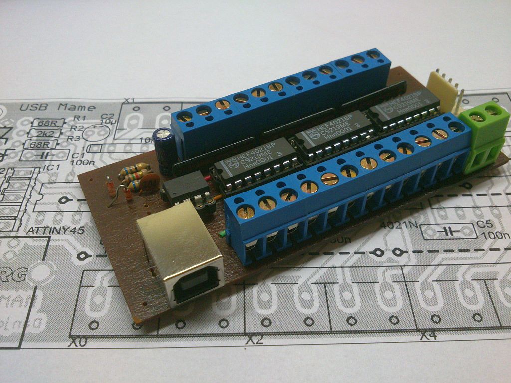
The previous board can be seen in the pictures below:
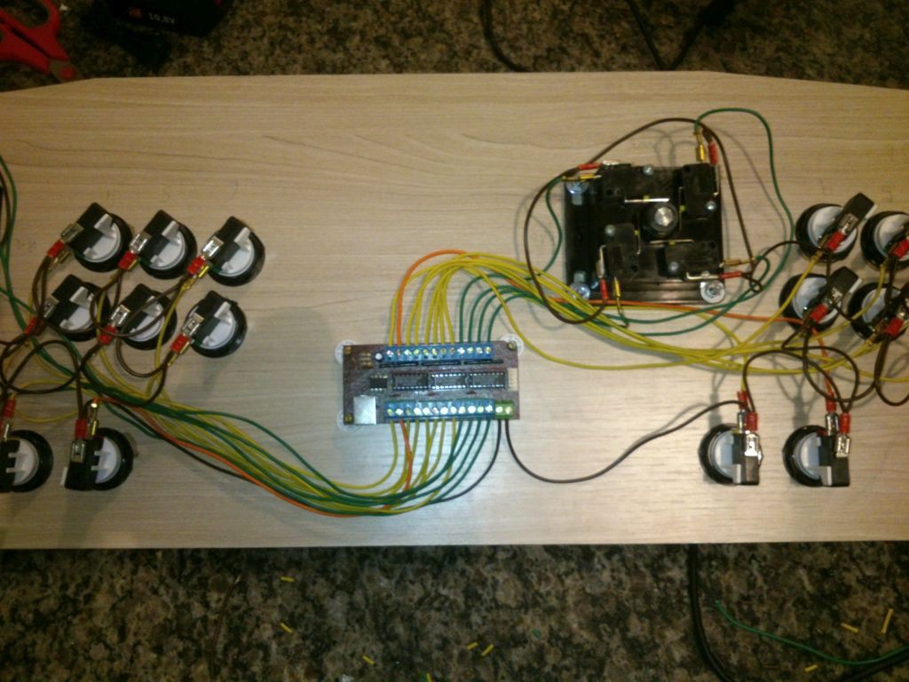
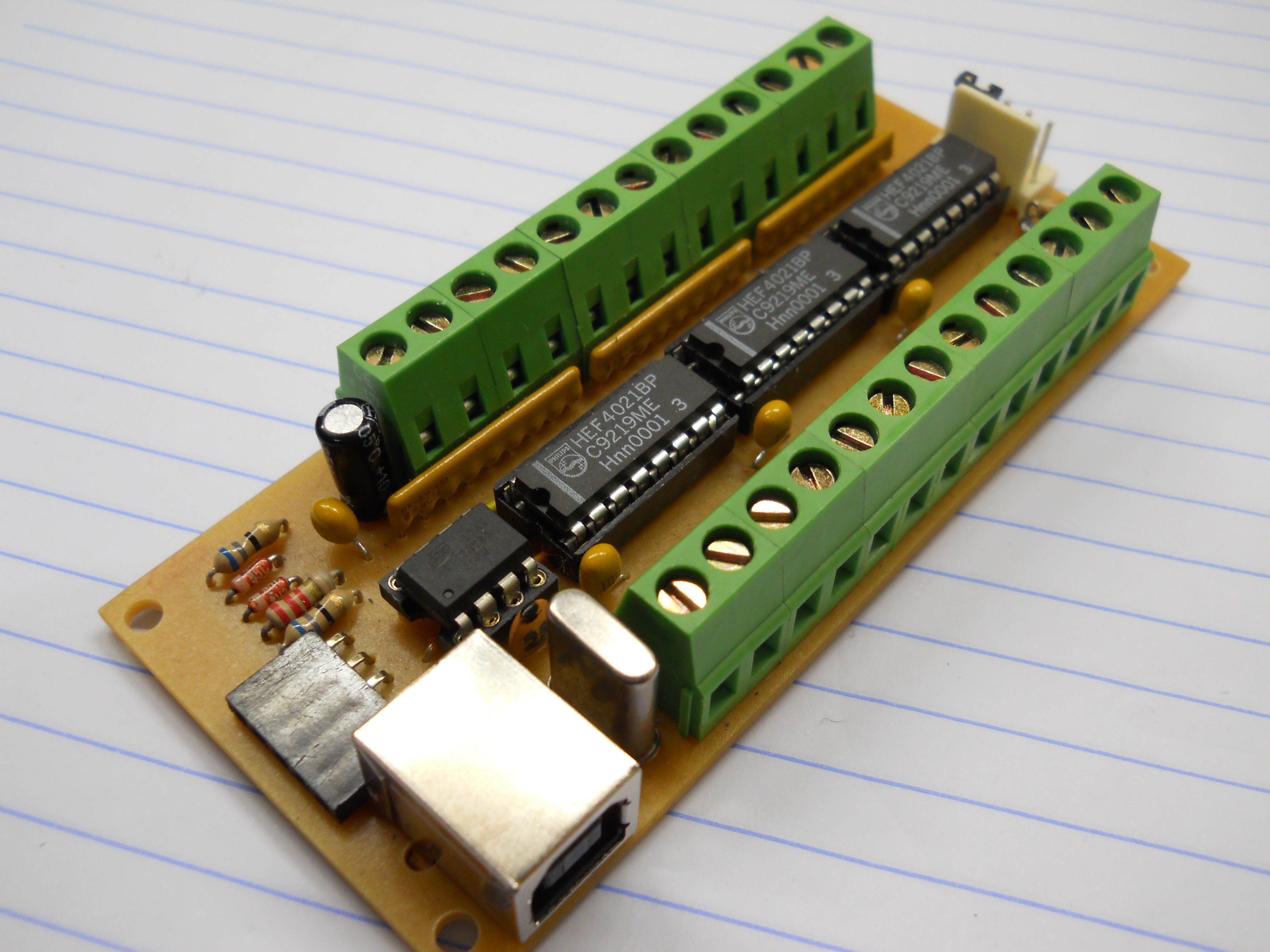
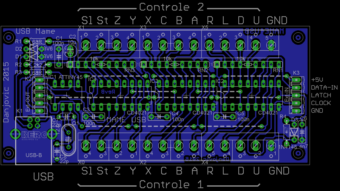
The new version which uses a crystal can be seen in the picture below.

  • 1 × ATTiny85 AVR microcontroller
  • 1 × CD4021 8 bit static shift register
  • 2 × BZX79 C3V6 Zener Diode
  • 1 × 10uF/16V Polarized Capacitor
  • 4 × 100nf Polyester/Ceramic capacitor

View all 14 components

  • A problem and a workaround

    danjovic08/22/2015 at 00:46 0 comments

    the main reason MAME-USB undergo a design change was the fact that it was not being recognized during a power-up/restart of windows. Well this design presented a bug that I was not able yet to trace but have the following symtoms:

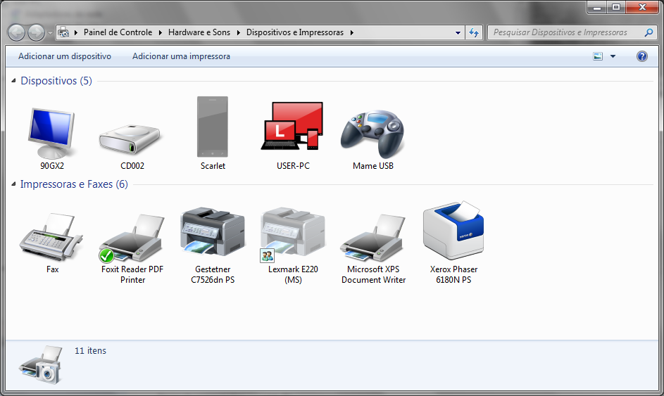
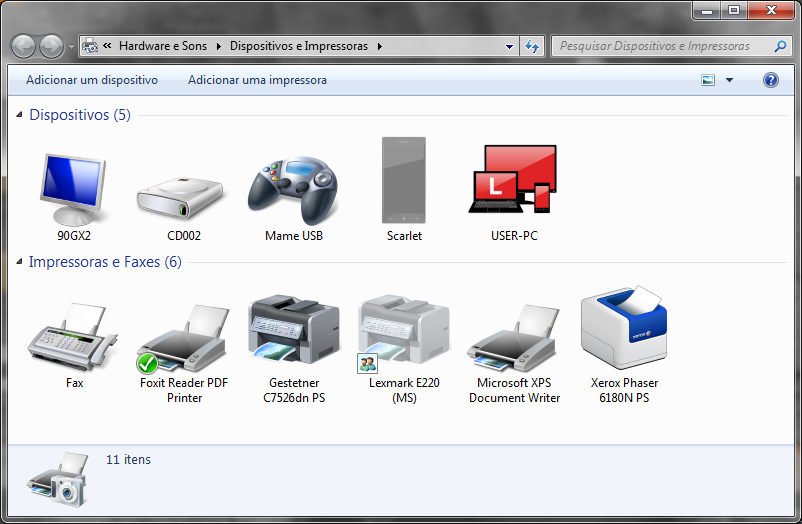
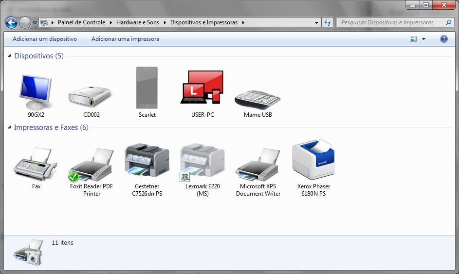
    The scenario is: The computer is running Windows 7 an has a 4 port hub. The MAME-USB Board is connected to port 1, and windows recognizes it as a game controller.

    After restart or cycling power, it stills being recognized as a game controller. Notice that it was enumerated before the Telephone (Scarlet)

    The computer is then powered down and the MAME-USB controller is changed to another port than port 1, let's say to port 2.

    Then, after computer is restarted, the device is recognized as a composite device that has a keyboard plus 3 game controllers (not shown in Devices And Printers)

    Then, If you unplug and then reconnect the USB cable, Windows still seeing the device as a composite keyboard.

    Next step is powerup/restart the computer. After that the device is always recognized a Keyboard controller, being enumerated before the cell phone (don1t have the screenshot, sorry)

    The conclusion is:

    When you connect the device with the computer working, windows recognizes the drivers accordingly and make some kind of cache for that USB port, thus the device can be left connected on the port (like the real use in a mame arcade)

    But, if the device is being detected for the first time at a given USB port __during powerup__ windows does not recognize it properly and assigh a composite keyboard device driver for it. Such driver is persistent.

    Now the workaround:

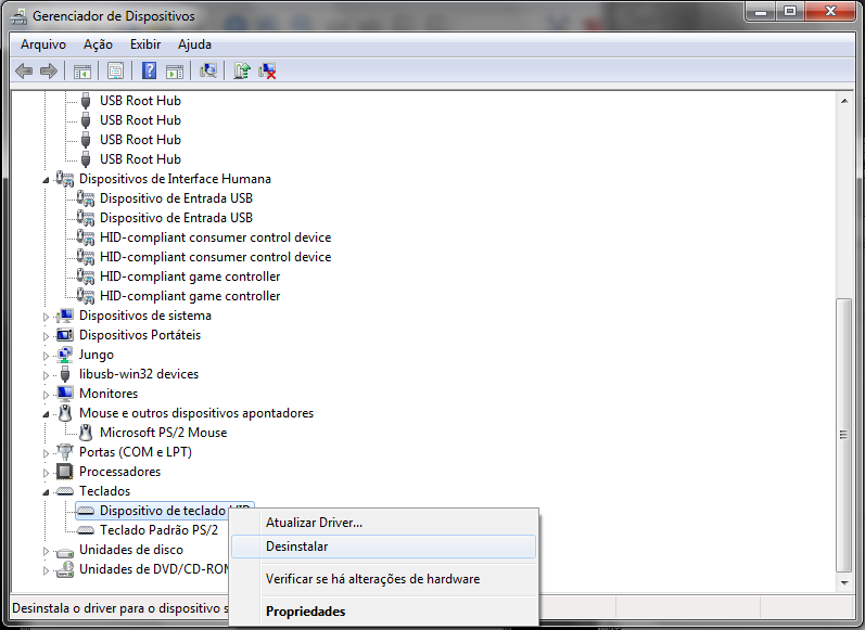
    To correct the detection of the device we shall make windows dissociate the keyboard driver and then unplug and replug the device.

    For doing that it is necessary to access the Device manager and search for the KEYBOARD tree, then right click on the "HID Keyboard Device" and choose "Uninstall" to unload the incorrect driver.

    Then windows will forget the wrong driver and automatically detect the game controller and associate the correct driver.

  • First working version

    danjovic08/21/2015 at 04:06 0 comments

    Found a bug on the function that shifted the bits from the shift registers. This function loops 8 times, one for each bit. The problem was that the clock pulse was being issued before each sample and that caused me to loose one bit.

    Wrong:

    data=0;
    for (i=0;i<8;i++) {
        pulse_clock();
        data<<=1;
        if (Sample_bit ()) data |=1.
    }

    Correct:

    data=0;
    for (i=0;i<8;i++) {
        data<<=1;
        if (Sample_bit ()) data |=1.
        pulse_clock();  
    }

    To find the bug I ran the code in an experiment board that generated the clock/latch signal to the shift registers and allowed me to print each byte that was being received.

    Bug found, firmware uploaded and... device not recognized!!

    Well, after loose some time _again_ on the fuse configuration I figured out that I was flashing the wrong hex file! Then I have left the fuses on the following configuration LFuse= 0xDF, HFuse=0x5F, and reflashed the ATTiny85 with the correct firmware. This time the beast worked! Windows 7 have recognized all four gamepads (two of them are dummy, though)

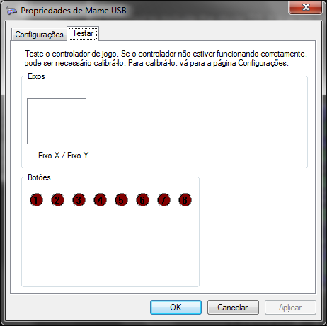
    Each controller has one directional and 8 buttons:

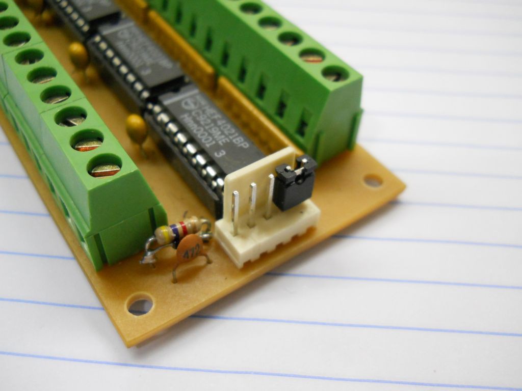
    Below are the pictures of the prototype.

    The second picture shows tho important things:

    1) When using only one board the Input Data pin shall be short circuited with the +5V line in order to simulate the remaining board with no key or button pressed (all bits in high).

    2) The speed-up diode of the LATCH signal soldered right under the 4K7 timing resistor.

    The hex file is already available as a link to my dropbox folder for this project. The code still needs to be cleaned and commented. The PCB on the links already contains the correction (insertion) of the speed up diode.

  • Digging in the firmware

    danjovic07/27/2015 at 06:33 0 comments

    Lost two days trying to make the firmware work. It was a good shellacking!

    First problem: For updating the controllers I have the following structure:

    void Update_Gamepads() {
    ...
       tmp1=Shift_8_bits();
       tmp2=Shift_8_bits();
       tmp3=Shift_8_bits();
       tmp4=Shift_8_bits();
       tmp5=Shift_8_bits();
       tmp6=Shift_8_bits();
    ...
    ...
    
    }

    For some reason, the firmware got stuck if I call the "Shift_8_bits()" function more than once. If I called the function only one time was ok.

    It took me one day to figure out the most problable cause was a stack overflow. I have replicated the variables and the Update_Gamepads() and related functions in a new project, without the USB code and it worked as expected (as seen in oscilloscope). Since was using the ATTiny45 and despite GCC inform that the amount of RAM usage was below 80 bytes, I've changed the target for ATTiny85 and recompiled the USB project. This time it worked as expected, I mean, no stuck on the Update_Gamepads function.

    The other day I spent trying to make the USB to recognize the device. This time the problem was in the USB initialization on the main() function. For some reason I could not define, the code I was using before did not worked. After replacing the startup code with the beginning of code from V-USB project the circuit started to be recognized wy windows, showing the 4 gamepads.

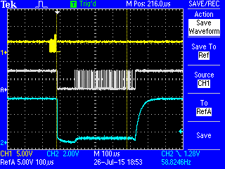
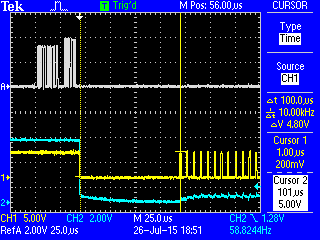
    Further enhancement was to synchronize the Updata_Gamepads() function with the end of a USB interrupt. This is necessary because if an USB interrupt occourred during the shifting of the bits, the state of the LATCH line might be changed, and the shift registers would be reinitialized with the parallel inputs, thus ruining the current reading (shifting) of the button states. For doing that I put the code to sleep everytime a new reading is necessary. Then after the next USB interrupt the code follows and a new reading begins. There is a delay of 100us before the reading, to avoid two quick usb interrupts to occour. During this time the CLOCK signal stays in LOW level, which makes the LATCH line goes to LOW level, allowing the shifting of the bits.

    if (mustPollControllers())  { // at ~16ms (60Hz)
        clrPollControllers();
        sleep_enable();
        sleep_cpu();
        sleep_disable();     // resume after IRQ
        Update_Gamepads();    // start with a delay of 100us
    }

    This technique of synchronizing the reading was borrowed from the N64/Gamecube controller to USB converter from Raphnet.

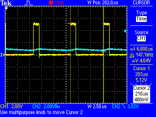
    In the picture below the yellow trace is the USB D+ signal, the white trace is the CLOCK signal and the blue trace is the LATCH signal.

    In the picture below the white trace is the USB D+ signal, yellow white trace is the CLOCK signal and the blue trace is the LATCH signal.Notice the 100us interval between the falling edge of CLOCK signal up to the first clocl pulse. Such delay is in the Update_Gamepads() function.

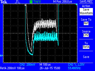
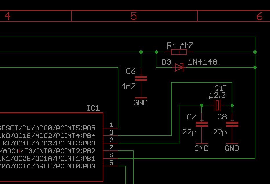
    In the meantime while debugging the code I've included a diode (D3) in the RC circuit that generates the LATCH signal for speed-up the falling edge of the signal as well as to keep such level at ~0.5Volts. Without the diode the LATCH line low level was close to 1V. In the pictures below the blue line is the LATCH signal with the diode and the white line is the signal without the diode.

    The updated circuit can be seen below.

    The PCB was modified to include the diode D3. It is at the downright position between the resitor R4 and capacitor C6

  • Defining some components and timing

    danjovic07/25/2015 at 19:37 0 comments

    Ran some tests to determine the values of the resistor and capacitor on the temporization network that generates the P/S signal from the CLOCK signal. Also changed the delay loops in the program in order to take less time to complete all the shifting.

    The resulting values are:

    • Resistor: 4K7
    • Capacitor: 4n7
    • Delay time from CLK low to P/S low: 100us (above 50us is OK)
    • Total time spent shifting the 48bits plus start and final delays: 442us. It might be necessary to synchronize the reading of the bits with the USB interrupts.
    • Bit Shift timing: 6,8us (174KHz)


  • PCB ready

    danjovic06/24/2015 at 00:44 0 comments

    This weekend I've etched the PCB for the project. Now I'm starting to assemble it.

View all 5 project logs

  • 1
    Step 1

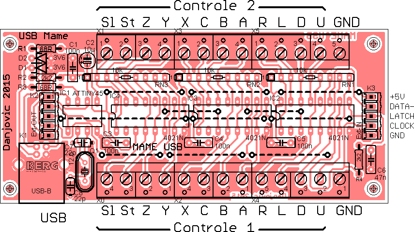
    Connection for the buttons can be seen in picture below:

    U,D,L,R are directional buttons (Up, Down, Left, Right)

    A,B,C,X,Y,Z are buttons (SNES nomenclature)

    Sl,St are also buttons, named after SELECT and START (also SNES nomenclature)

View all instructions

Enjoy this project?

Share

Discussions

Similar Projects

Does this project spark your interest?

Become a member to follow this project and never miss any updates