-
1Step 1
Hardware
[Update: 2015/07/01 - Added additional info for those connecting the Nano Alarm to higher voltage (24, 36, 48 VDC eBike) batteries. ]
NOTE- Before you start soldering, it's a good idea to plug your Arduino into your PC via the FTDI adapter and verify that it works and that you can upload sketches. It sucks to find out you've got a bad one after all the soldering is complete...
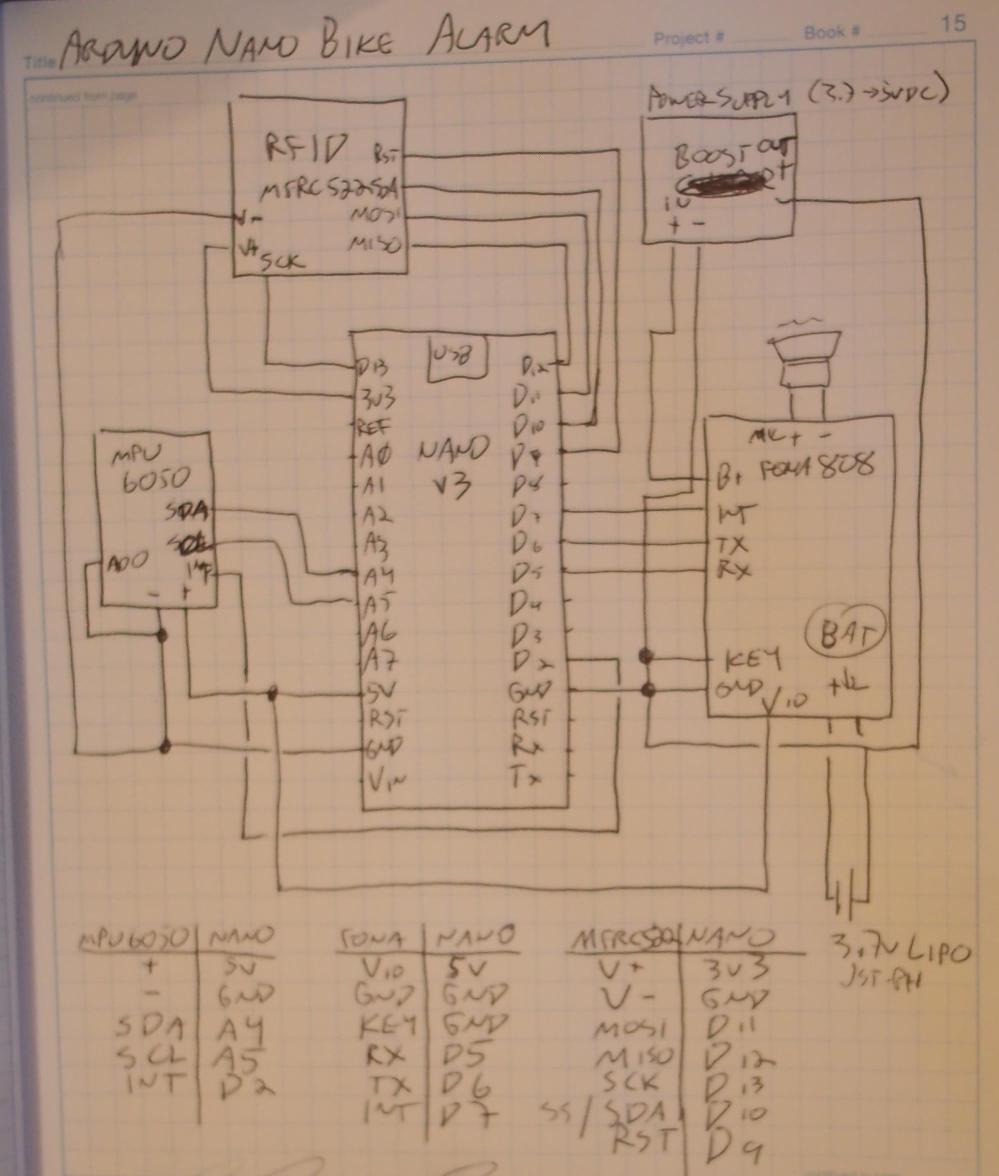
The hardware is fairly easy to assemble here. Each component uses a different bus and different pins. The only pins with multiple connections are the Vcc and Gnd pins. This makes it easy to wire point-to-point for the smallest device footprint. See the wiring diagram below for details.
![]()
The circuit above shows the original 5V prototype. The newest version uses the Arduino Pro Mini at 3.3V and does not have the Boosting 5V regulator. Instead the Raw pin of the Arduino Mini is connected to the Bat pin of the FONA 808. Otherwise the wiring is pretty much the same.
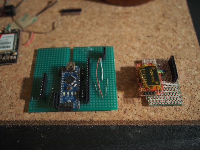
Original prototype (left) next to the much smaller v2 layout(right)
![]()
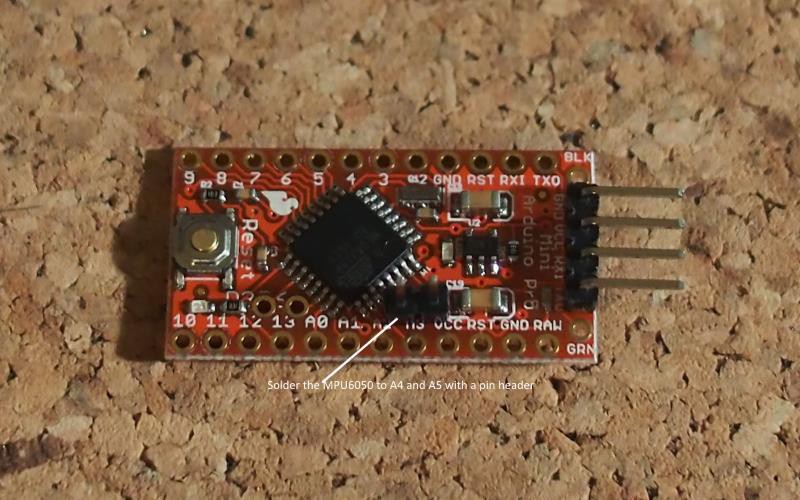
To construct the Nano Bike Alarm First you'll want to get the MPU6050 mount set up. To do that, solder 2 male header pins to the A4 and A5 on the Arduino.
![]()
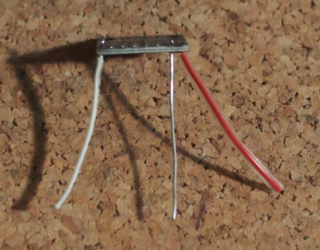
Now solder some short jumper wires to the VCC, Gnd and Int pins on the MPU6050.
![]()
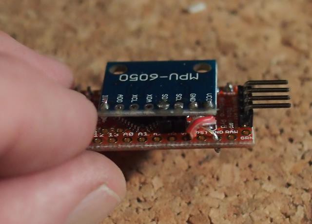
Now Solder the wire from the Int pin to pin D2 on the Arduino (leave yourself a little extra wire for slack.) After that take 2 lengths of pin header and solder it to all the other pins on the top row of the Arduino (i.e. everything except D2). Now you can lay the MPU6050 upside-down on the Arduino so that the SDA and SCL pins on the MPU connect to A4 and A5. (Not as confusing as it sounds, see photo below). After that you can connect the Gnd and Vcc jumpers (don't solder the Vcc jumper yet though!)
![]()
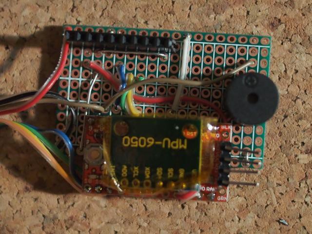
Now take another short jumper wire and connect it to the bottom of the Vcc pin on the Arduino and solder them both, then solder the Arduino to the proto-board as shown in the photo below.
![]()
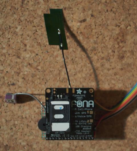
Next solder some female header on to the other half of the proto-board for the FONA. and connect jumper wires so that-
- Bat on the FONA goes to Raw on the Arduino
- Gnd on the FONA goes to Gnd on the Arduino
- Vio on the FONA goes to Vcc on the Arduino
- Rx on the FONA goes to pin D5 on the Arduino
- Tx on the FONA goes to pin D6 on the Arduino
- RST on the FONA goes to pin D7 on the arduino
- Key on the FONA goes to Gnd on the Arduino
Next solder the beeper to the proto-board and connect the + pin to D8 on the Arduino and the other pin to Gnd (using jumpers). You can also use a bit of Kaptan tape to insulate the different layers from each other.
![]()
Next solder the RFID to the alarm so that-
- 3.3V on the RFID goes to Vcc on the Arduino
- Gnd goes to Gnd
- Rst on the RFID goes to pin D9 on the Arduino
- SDA on the RFID goes to Pin D10 on the Arduino
- MOSI on the RFID goes to pin D11 on the Arduino
- MISO on the RFID goes to pin D12 on the Arduino
- SCK on the RFID goes to pin D13 on the Arduino.
Congratulations! You are done building the hardware!
The photo below shows the completed Nano Bike Alarm.
![]()
-
2Step 2
Software Configuration
Once you have the hardware complete, extract the package and open the 'newKey' sketch.
In the Arduino IDE, edit this sketch and change the hex values for the newA and newB keys and for the tokenBlockData array. The keys are 6 bytes long. The token block is 16 bytes. To generate random bytes for your key and tokn you can use https://www.random.org/bytes/ (though you'll probably have to add '0x' to bytes they give you....)
Once you have customized your keys and token you can compile and run the newKey sketch. Once the sketch is running, connect to the Serial monitor in the Arduino IDE and follow the prompts to provision your PICC. At the end of the process if it's complete you will be given the UID of the PICC card. Write that down for the next step. (You can also unprovision PICC's or test the authentication with the newKey sketch as well.)
Once that is complete open the Bike-Alarm sketch and scroll to the USER CONFIG section (show below). You don't have to mess with most of those options. All you really have to do to configure the Nano Alarm is-
- Set your alarmKeyA to the key byte array you generated for key A of the newKey sketch
- set your tokenBlockData to the values you used for the newKey sketch
- place your key UID in one row of the keyUIDs array (make sure the number of rows matches the N_UIDS var or the sketch won't compile.
- put your cell # in the alertphone variable
// BEGIN USER CONFIG

// the following values are user configurable. Key, keyUIDs and blockTokenData must match
//    what's in the newKey sketch for authentication to succeed.

//the cell phone number to send alert SMS to
char alertPhone[] = "8005551212"; // Change this to your cell #!!!!

//alarm sensitivity in percentage
byte alarmSensitivity = 60; //set sensitivity of alarm 1 = lowest 100 = highest

//this is key A for our RFID (Note : DO NOT use the default key of FFFFFFFFFFFF or the one provided!!! Make up your own.)
byte  alarmKeyA[6] = { 0x3b, 0x32, 0xa8, 0xc3, 0x3f, 0xf5 };

//put the UIDs of your RFID PICCs here and define the number of keys...
// this is the number of provisioned UIDs
#define N_UIDS   3

// These are the provisioned UIDs, one per row. You MUST add your key UIDs here after you provision.
// MUST be one key per row and match the number of keys in N_UIDS above.
byte keyUIDs[N_UIDS][4] =  {
    { 0x00, 0x00, 0x00, 0x00 }, //key 1 UID
    { 0x00, 0x00, 0x00, 0x00 }, //key 2 UID
    { 0x00, 0x00, 0x00, 0x00 }  //key 3 UID
};

//define the sector and blocks used by the application
byte sector = 1;

//this is the token block (i.e. THIS IS YOUR KEY!) Change it to something unique
byte tokenBlockData[16]    = {
    0x13, 0x52, 0xf2, 0x5b,
	  0xc8, 0x8c, 0x2d, 0xb0,
	  0x7a, 0xe7, 0xcd, 0x86,
	  0xbc, 0xe9, 0xf2, 0x0f
};

byte settleTime = 15;  //time to let the MPU settle after arming. Increase if you get false positive alarm right after arming.

//   Integrate some loop management to limit SMS and keep from TEXT BOMBING ourselves
int messageDelay = 1200; //minimum delay between messages in loops  (one loop is around 200mS so 1200 = 1200 * 0.2 ~ 240 seconds
int alertDelay = 6000; // delay for follow-up alerts once triggered.(in loops) Set to 0 to only send alerts if moving...
boolean pretend = false; // do not send text messages if true...

//END USER CONFIG
In the snippet above you can see the available configuration options. A brief Description follows:
- alertPhone - The phone number to send SMS alerts to
- alarmSensitivity - The sensitivity of the motion sensor. Needs to be between 1 and 100. HIgher = more sensitive to movement
- alarmKeyA - The key to unlock the PICC. Must match key A in the newKey sketch!
- N_UIDS - The number of provisioned PICCs (i.e. how many keys you have
- keyUIDs - The UIDs of each provisioned key, one per line. Your key's UID must be here to disarm the alarm!
- sector - which sector to use on the PICC may be any between 1 and 15. DO NOT use sector 0 as that contains the cardUID. Unless you are using the same PICC elsewhere, you can leave this alone.
- tokenBlockData - This is a string of random bytes that serves as the 'secret' or in our authentication scheme. It must be the same in both this sketch and newKey for your keys to disarm the alarm!
- settleTime - how long to allow the MPU readings to settle after arming. Set longer if you get false positive alerts right after arming.
- messageDelay - The minimum allowed # of loops between text alerts. (each loop is around 0.2 sec). Keeps you from text-bombing yourself... Default of 1200 is around 4 minutes.
- alertDelay - How long to wait before sending follow up location reports after the alarm is tripped. The default of 6000 is around 20 min. You can also set it to 0 to disable follow up messages and only send alerts when moving.
- pretend - Don't send SMS, beep instead. (does a short-med-short beep if triggered) This option is allows you to prevent SMS from sending and just beep at you instead. It's useful if you need to adjust your sensitivity on the motion sensor.
Note-> If you have problems uploading the sketch, unplug your FONA from the Nano Alarm and try without it. Also you will either have to connect the reset pin or manually reset the Arduino Pro Mini right when you upload the sketch. (See this- https://www.arduino.cc/en/Guide/ArduinoMini)
-
3Step 3
Vehicle Mounting
Once it's set up, the last thing to do is install it on your bike. It can be hidden in the seat or for eBikes inside the battery box. (If your battery box is metal, you may need to futz with antenna and RFID reader placement to ensure you get a GPRS signal and GPS fix.)
Wherever you install it, there should be a pocket or sleeve to hold the RFID card which is positioned near and parallel to the MRFC522 card reader. For aluminum battery boxes, you'll also have to think about antenna and RFID reader placement. Test your set-up regardless to verify GSM and GPS reception. If the location you install the alarm is not weatherproof, then you may want a small plastic case to enclose it. (Whereas if it's sewn into the seat of a bicycle then size will be paramount and you may just want to heat-shrink wrap the components. The vehicle will dictate the construction methods.)
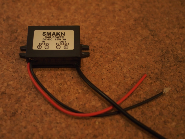
If you are installing into a motorcycle/ATV/snow machine, then you can use a 12VDC->5VDC converter to and have the vehicle recharge the alarm's battery. To do this simply connect the 5VDC out from the converter to the +5V (and Gnd) pin of the FONA.
Another option if you're going to connect it to the vehicle's battery is to not use a battery at all for the FONA. The plus is that it's a simpler system. The minus is that if the thief disconnects the vehicle battery then the GPS quits phoning home. If you wish to power the FONA directly from the vehicle battery you need to use an adjustable step-down regulator and set the output voltage to 3.9VDC (instead of 5) then connect this output to the +Bat and Gnd of the FONA (or to the JST-PH). Do not connect the +5V of the FONA. (to anything)
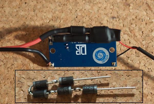
For eBike, connecting the Nano-Alarm to the bike's battery takes more planning. DC Adapters for vehicle mounting like the one below are available in 12VDC, 36VDC and 48VDC and offer an easy way to recharge the alarm. Output connections are the same as for other vehicles. But make sure that the converter is designed to handle the actual voltage of your system, not the 'on-paper' voltage of the battery. As an example, a 36V LiFePO4 battery has 12 cells with a fully charged voltage of 3.65V per cell. So our 36V battery is actually 43.8V when fully charged. A 48V LiFePO4 tops off at 58.4V!
Also please test your DC->DC converter output to ensure that it is only delivering the desired voltage before plugging your alarm into it!**
![]()
If you need to reduce the input voltage for your DC->DC converter just a few volts, you can connect some diodes in series with the DC->DC power supply. Below I used 1N5408 diodes which are rated for 3A and drop the voltage about a volt each. This gives the LM2596 board shown an extra 5V of headroom...
![]()
You can use a larger/smaller battery than 2500mAh as well. Battery usage while armed is around 50-100mA assuming you have a decent GSM signal. (that's with the GPS on too!) So you can estimate how long a battery will last by dividing the battery capacity by 60. So for example a 5000mAh could stay armed for as long as 100 hours.) If it's eating a lot of battery, getting a better GPS and/or GSM antenna can help extend battery life dramatically simply by allowing the FONA to work less to amplify the radio signals it receives and transmits.
**Note - a large number of the switching power supplies on fleaBay include counterfeit ICs. For any power supply you get online - Test it on your actual working voltage for several hours at least and ensure that it delivers only the stated voltage and does not get hot, smoke die, etc... Bad one's tend to short out within a few minutes, delivering the full input voltage to the 5V output. If that's going to happen then you want it to be before you plug your Nano-Alarm into it. (You can use a 12V incandescent light bulb or a sufficiently large resistor as a test load.)
-
4Step 4
Usage
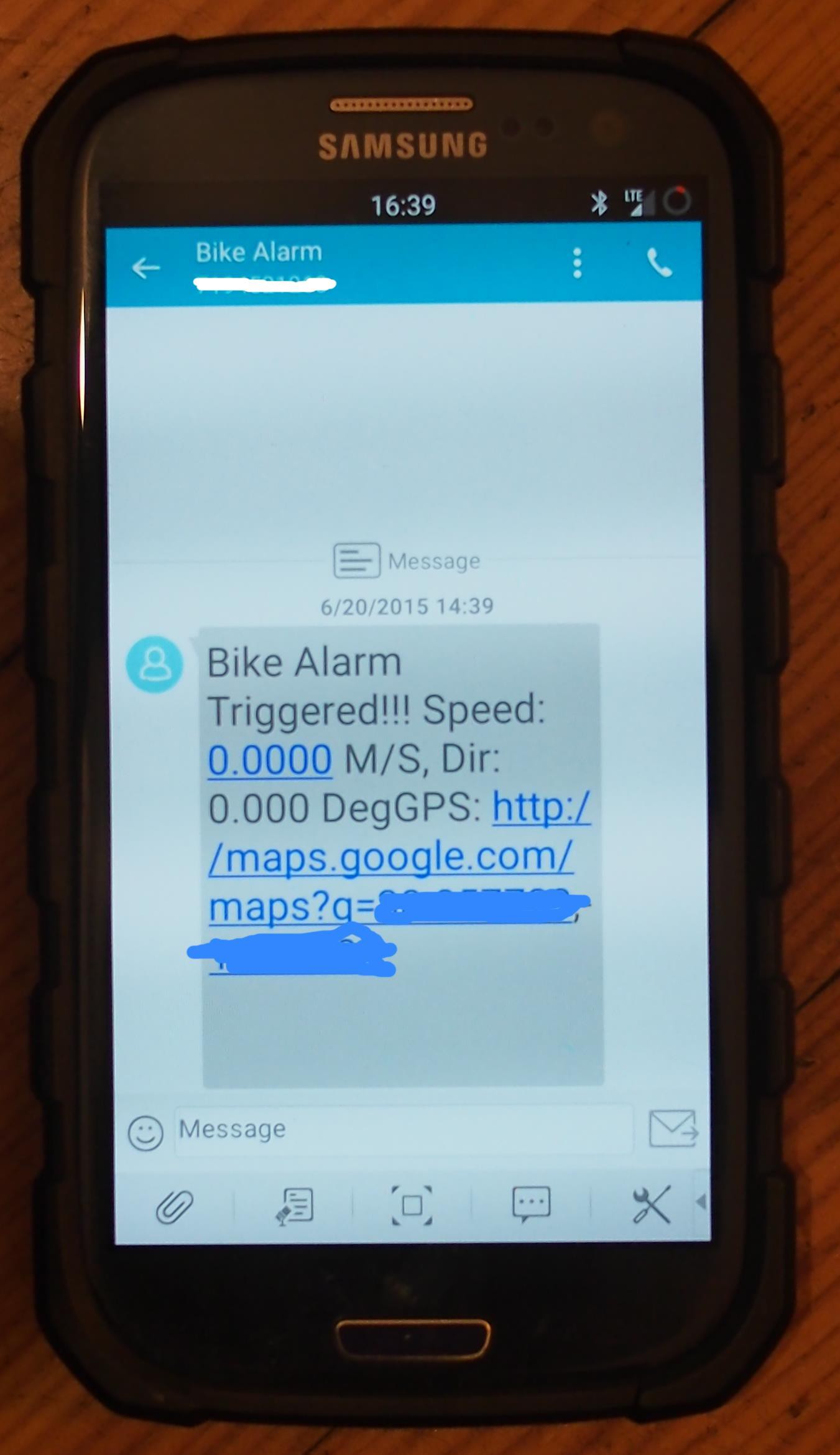
To use simply power on once the unit is vehicle-mounted. The alarm is DISARMED when a provisioned key is in range of the reader and ARMED otherwise. Once ARMED, GPS is activated. If motion is sensed, the alarm sends a text message to the number specified in the sketch, including a Google maps link of the GPS coordinates, heading and speed. The alarm has an adjustable delay in between messages to keep from text-bombing ones' self. Default is 3 minutes.
The Nano Bike Alarm is designed to be 'out-of-sight, out-of-mind' and uses only audio beeps for user feedback. When you hold your RFID key up to the alarm reader you will hear 3 short beeps if the key is accepted or one short beep if it is not. When you remove your key from the reader you will hear one long beep as the alarm arms. However the alarm itself is silent. There is no beeping at all if the alarm is triggered. It merely silently texts you.
In the event the alarm fails to initialize hardware on start-up it will beep continuously to alert the user that it's 'broken'.
![]()
Nano Bike Alarm
An affordable RFID, motion-sensing, anti-theft alarm and GPS tracker for bicycles, e-bikes and other small vehicles. Based on Arduino
 Alpha Charlie

Discussions
Become a Hackaday.io Member
Create an account to leave a comment. Already have an account? Log In.
weird, i posted here this morning but the post isn't showing up
Was curious if i could replace the RFID you use with one with more range (1.5 metres or so) so that the alarm is deactivated when you are in range - like a key fob for newer cars. ..
Also, if i was to use the motorbike to recharge the battery, where would i plug the 12v to 5v step down converter to? The auxiliary fuse in the fuse box?
Regards,
Mick
Are you sure? yes | no
Hi Alpha Charlie,
I'm trying to build your project but I'm facing some difficulties. Especially with the MPU6050 interrupt attached to a FONA Shield + Arduino Uno.
Would you help me please ?
Thank you
Are you sure? yes | no
I can´t find the link to download the package and use the sketches. Can you please provide it to me?
Are you sure? yes | no
it's in the project links (which is on the left below 'team') but here is the link- https://github.com/alphacharlie/nano-bike-alarm
Are you sure? yes | no