 Jose Barreiros
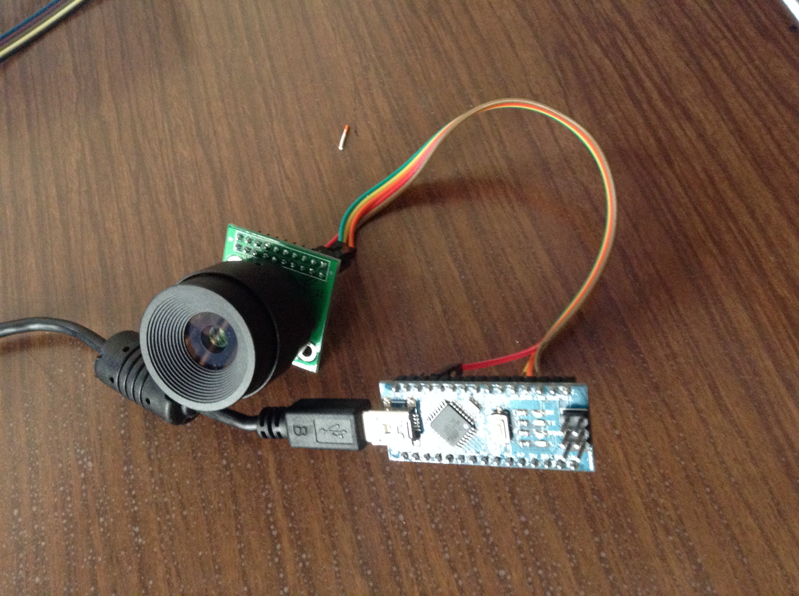
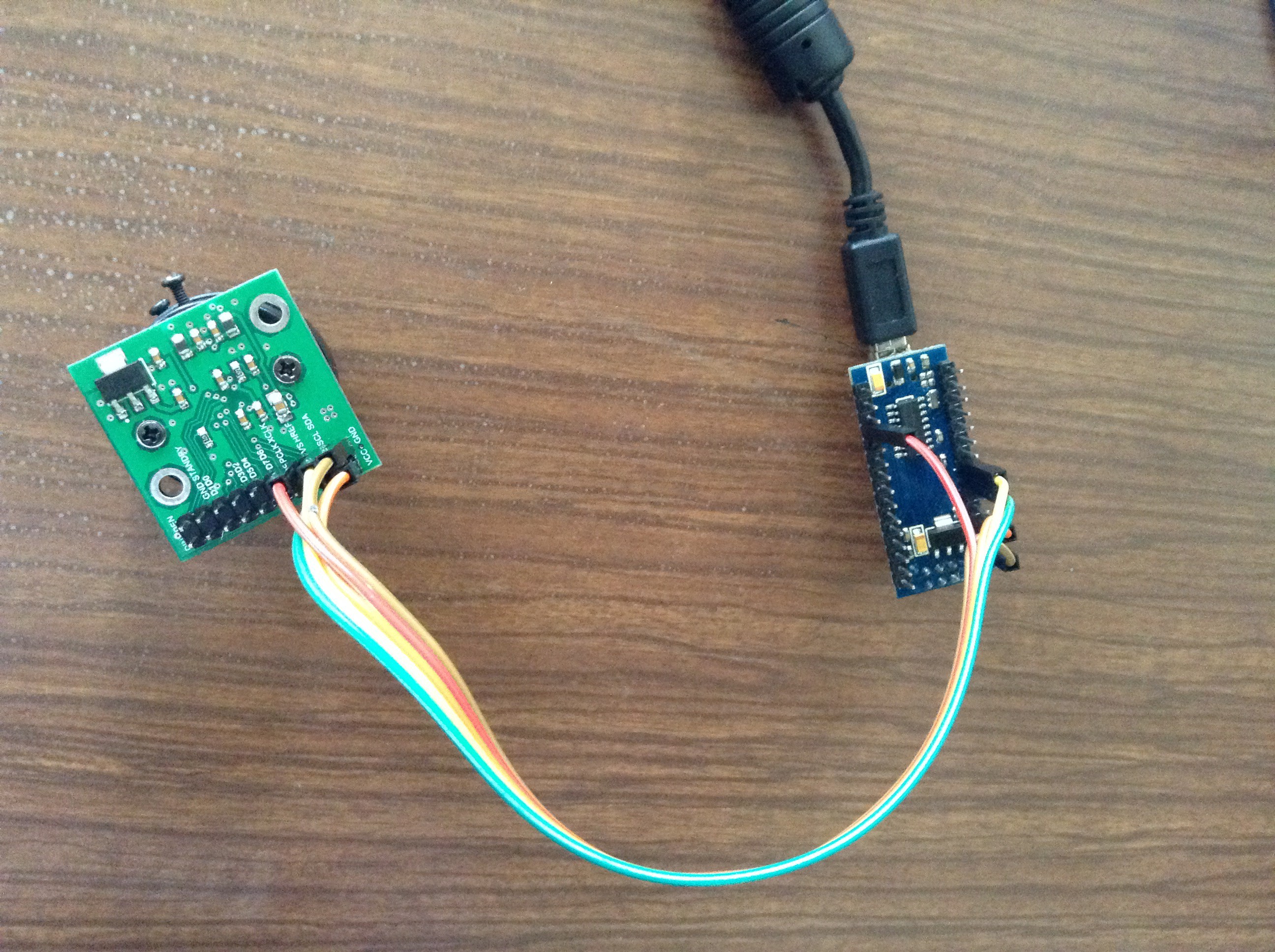
For checking the MT9D111 two wire interface I started wiring the camera module to an Arduino Nano. Then, I programmed the Arduino based on the 16 Bit Register Read and Write Examples in page 9 to 11 of the Developer Guide.
Wiring:
MT9D111 ------ Arduino
GND ------------ GND
XCLK ----------- D9
VCC ------------ 5V
GND ------------ GND
SCL ------------- A5
SDA ------------- A4
After a few hours trying to generate the 8Mhz clock on Arduino, I realize that timer1 could perform that task without compromising other functions such as delay() and millis().
Finally, the results were successful, Arduino could write and read registers in MT9D111 Camera Module with these two custom functions:
write_reg(register_address, page, data_msb, data_lsb)
read_reg(register_address);
/*
Author: Jose Barreiros
Date: 01/June/2015


This code is Arduino Nano compatible, the READ CODE is based on the work of Anthony Balducci:
https://github.com/anthonybalducci/MT9D111-Teensy-3.1/blob/master/MT9D111_16-bit_Register_Read_Example.ino


Useful note from Anthony Balducci code:
"The MTD9111 Developer Guide states that 0xBA and 0xBB are the default read/write addresses respectively.
   However, it is important to note, while converting 0xBA and 0xBA to binary at first 'appears' to give us
   two distinct addresses:

   (Write) 0xBA --> 10111010
   (Read)  0xBB --> 10111011

   The two values only different in their LSB (least significant bit), or in this case, the first value on the
   'right'. The '0' / '1' in this position is what specifies the write (0) or read (1) condition accordingly.
   In the Arduino language the LSB read/write portion is already built into the Wire.write / Wire.read commands,
   thus the original register addressess specified must be truncated by the read/write bit to seven bits, leaving
   us with 1011101 --> Ox5D in both cases."
*/


#include <Wire.h>
#include <avr/io.h>
#include <util/delay.h>
#include <TimerOne.h>
#include <avr/interrupt.h>


#define TMR1 0  //Timer1 used for 8Mhz PWM Output
void setup()
{
 delay(500);  //Initial delay
 Wire.begin(); // join i2c bus as master
 Serial.begin(9600);
 Serial.println("MT9D111 Camera Module + Arduino Nano");
 Serial.println("Read and Write 16-bit register value example");
 Serial.println("*  Read expected value = 0x1519 from Register 0x00");
 Serial.println("*  Write value = 0xA5F0 to Register 0x20:1");
 Serial.println();
//Generating 8MHZ PWN on pin9


 pinMode(9, OUTPUT); // output pin for OCR2B


 TCCR1B |= (1 << CS10);  //selecting prescaler 0b001 (Tclk/1)
 TCCR1B &= ~((1<<CS12) | (1<<CS11));    // turn off CS12 and CS11 bits
 TCCR1A |= ((1<<WGM11) | (1<<WGM10));  //Configure timer 1 for TOP mode (with TOP = OCR1A)
 TCCR1B |= ((1<<WGM13) | (1<<WGM12));
 TCCR1A |= (1 << COM1A0); // Enable timer 1 Compare Output channel A in toggle mode
 TCCR1A &= ~(1 << COM1A1);
 TCNT1 = 0;
 OCR1A = TMR1;

init1(); //perform code just 1 time
}


void loop()
{


}


void init1(){
int16_t a;
  delay(500);  //wait until start
    Serial.print("Read result from register 0x00");
  a=read_reg(0);
   Serial.println();
    Serial.print("0x");
  Serial.println(a, HEX);  //print result
    Serial.println();

  Serial.print("Read original data from register 0x20:1");
  a=read_reg(32);
  Serial.println();
  Serial.print("0x");
  Serial.println(a, HEX);  //print result
    Serial.println();


 //Enable this part for writing register

 // Serial.print("Writing 0xA5F0 in register 0x20:1");
//    Serial.println();
 // write_reg(32,1,165,240);


  // Serial.print("Read new value from register 0x20:1");
  //a=read_reg(32);
    // Serial.println();
  //Serial.print("0x");
  //Serial.println(a, HEX);  //print result
    //Serial.println();
}


void write_reg(int direccion, int page, int data_msb, int data_lsb){
  delay(5);  //5ms
  Wire.beginTransmission(93); // transmit to device 93, Camera Module
  Wire.write(240);   //page register address
  Wire.write(0);
  Wire.write(page);   //select page 0/1/2
  Wire.endTransmission(1);    // stop transmitting

  Wire.beginTransmission(93); // transmit to device 93, Camera Module
  Wire.write(direccion);   //register address 8bit, decimal
  Wire.write(data_msb);  //msb
  Wire.write(data_lsb);  //lsb
  Wire.endTransmission(1);    // stop transmitting
}


int16_t read_reg(int direccion){
  delay(5);  //5ms
  Wire.beginTransmission(93); // transmit to device 93, Camera Module
  Wire.write(direccion);   //register address 8bit, decimal
  Wire.endTransmission(1);    // stop transmitting


 Wire.requestFrom(93,2,1);   //request value form device 93, 2 bytes with stop bit
 int16_t result = ((Wire.read() << 8) | Wire.read());  //read 16 bits
return result;
}
Discussions
Become a Hackaday.io Member
Create an account to leave a comment. Already have an account? Log In.
Hey, first of all thanks for taking the time to post up your progress.
I am using the same module but used a mega to communicate using its I2C. i used a slightly modified version of your code, however register 0x00 value read gives me back 0xFFFFFFFF and not 0x1519
i did the following:
1. Used external pullups of 4.7k but got the same result
2. Checked the hardware again. The connections are ok
3. Used another module, results are the same.
Not sure why it's behaving like this. did you guys face similar problems?
Are you sure? yes | no
Ok got something out but not the same values. the used a logic analyzer to check whether clock signal was coming out.
got it to work with a 6Mhz clock
Are you sure? yes | no
I was using two different types of MT9D111 modules (green and blue pcb) and the green one showed correct values
Solved it, thanks for the code, didnt used the clock out from the arduino but from STM32F429ZI (6Mhz)
Are you sure? yes | no